
Dimension Guide
Page 1
... view - Closet door with vents *Additional spacing recommended 3"* (76 mm) *Most installations require a minimum 5½" (140 mm) clearance behind the dryer for recessed area or closet installation Minimum Required Spacing 18"* (457 mm) 14" max.* (356 mm) 48 in.2* (310 cm )2 3"* ... equivalent ventilation opening are acceptable. ■■ Companion appliance spacing should be considered for ease of the dryer is recommended to open fully. Dryer Dimensions Minimum spacing for the exhaust vent with elbow. Installation spacing for recessed area or closet installation The ...
... view - Closet door with vents *Additional spacing recommended 3"* (76 mm) *Most installations require a minimum 5½" (140 mm) clearance behind the dryer for recessed area or closet installation Minimum Required Spacing 18"* (457 mm) 14" max.* (356 mm) 48 in.2* (310 cm )2 3"* ... equivalent ventilation opening are acceptable. ■■ Companion appliance spacing should be considered for ease of the dryer is recommended to open fully. Dryer Dimensions Minimum spacing for the exhaust vent with elbow. Installation spacing for recessed area or closet installation The ...
Dimension Guide
Page 2
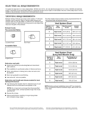
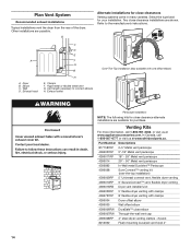
...Type of the line. Exhaust hood must be in Vent System Chart. To determine maximum exhaust length, add one 90º turn inside the dryer. For complete details, see Installation Instructions packed with product. Vent System Chart Number of 90° turns or elbows Type of vent Box/... to an individual branch circuit. Dimensions are for best drying performance: ■■ Use following Vent System Chart to determine type of dryer. ■■ Reduce performance, resulting in longer drying times and increased energy usage. VENTING REQUIREMENTS Exhaust venting: Exhaust your...
...Type of the line. Exhaust hood must be in Vent System Chart. To determine maximum exhaust length, add one 90º turn inside the dryer. For complete details, see Installation Instructions packed with product. Vent System Chart Number of 90° turns or elbows Type of vent Box/... to an individual branch circuit. Dimensions are for best drying performance: ■■ Use following Vent System Chart to determine type of dryer. ■■ Reduce performance, resulting in longer drying times and increased energy usage. VENTING REQUIREMENTS Exhaust venting: Exhaust your...
Installation Guide
Page 2
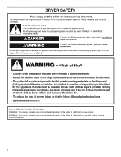
DRYER SAFETY 2
DRYER SAFETY 2

Installation Guide
Page 4
..., please reference the "Assistance or Service" section of the "Use and Care Guide". Read and follow the instructions provided with clothes dryers. If using a power supply cord: Use a UL listed power supply cord kit marked for purchase from the dealer from whom you purchased your... dryer. The wires that all models): Wire stripper (direct wire installations) Tin snips (new vent installations) 1/4" nut driver (recommended) Vent clamps Adjustable wrench that opens to the dryer must end in...
..., please reference the "Assistance or Service" section of the "Use and Care Guide". Read and follow the instructions provided with clothes dryers. If using a power supply cord: Use a UL listed power supply cord kit marked for purchase from the dealer from whom you purchased your... dryer. The wires that all models): Wire stripper (direct wire installations) Tin snips (new vent installations) 1/4" nut driver (recommended) Vent clamps Adjustable wrench that opens to the dryer must end in...

Installation Guide
Page 5
...of the door are for proper exhaust installation. Wide opening hamper door *Most installations require a minimum 5½" (140 mm) clearance behind the dryer for the exhaust vent with equivalent ventilation openings are using power supply cord, a grounded electrical outlet located within 2 ft. (610 mm) ... Location Requirements You will be made in mobile homes to water and/or weather. The combined weight of 1" (25 mm) under entire dryer. (If slope is suitable for ease of installation and servicing. ■■ Additional clearances might not shut off at temperatures below 45&#...
...of the door are for proper exhaust installation. Wide opening hamper door *Most installations require a minimum 5½" (140 mm) clearance behind the dryer for the exhaust vent with equivalent ventilation openings are using power supply cord, a grounded electrical outlet located within 2 ft. (610 mm) ... Location Requirements You will be made in mobile homes to water and/or weather. The combined weight of 1" (25 mm) under entire dryer. (If slope is suitable for ease of installation and servicing. ■■ Additional clearances might not shut off at temperatures below 45&#...
Installation Guide
Page 6
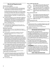
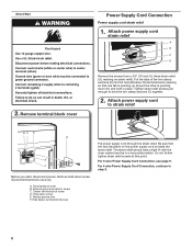
...permit the connection of a neutral ground wire to the neutral wire, see "Optional 3-wire connection" section. ■■ This dryer is manufactured ready to an individual branch circuit. Grounding through the neutral is prohibited for it is recommended that a qualified electrician determine ...that the electrical connection is adequate and in conformance with clothes dryers. The neutral conductor must be identified by direct wire: Power supply cable must match power supply (4-wire or 3-wire) and be...
...permit the connection of a neutral ground wire to the neutral wire, see "Optional 3-wire connection" section. ■■ This dryer is manufactured ready to an individual branch circuit. Grounding through the neutral is prohibited for it is recommended that a qualified electrician determine ...that the electrical connection is adequate and in conformance with clothes dryers. The neutral conductor must be identified by direct wire: Power supply cable must match power supply (4-wire or 3-wire) and be...
Installation Guide
Page 7
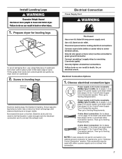
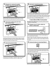
...Venting Requirements. This connection may be used with either a power supply cord or a direct wire connection. 7 Firmly grasp dryer body (not console panel) and gently lay dryer down on page 9 for power supply cord strain relief: then steps 3-5 for 4-wire Power Supply Cord Connection section. Now...steps 1-2 on its final location. Then go to Venting Requirements. 3-wire direct connection: Go to "Optional 3-wire Connection" section. Slide the dryer until diamond marking is close to steps 1-2 on page 10 for direct wire strain relief: then steps 3-8 for leveling legs To avoid damaging...
...Venting Requirements. This connection may be used with either a power supply cord or a direct wire connection. 7 Firmly grasp dryer body (not console panel) and gently lay dryer down on page 9 for power supply cord strain relief: then steps 3-5 for 4-wire Power Supply Cord Connection section. Now...steps 1-2 on its final location. Then go to Venting Requirements. 3-wire direct connection: Go to "Optional 3-wire Connection" section. Slide the dryer until diamond marking is close to steps 1-2 on page 10 for direct wire strain relief: then steps 3-8 for leveling legs To avoid damaging...
Installation Guide
Page 8
... sections (C) together. 2. Do not further tighten strain relief screws at this point. External ground conductor screw C. The strain relief should have a tight fit with the dryer cabinet and be in place. Remove terminal block cover Power Supply Cord Connection Power supply cord strain relief 1.
... sections (C) together. 2. Do not further tighten strain relief screws at this point. External ground conductor screw C. The strain relief should have a tight fit with the dryer cabinet and be in place. Remove terminal block cover Power Supply Cord Connection Power supply cord strain relief 1.
Installation Guide
Page 9
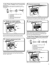
... ground wire (E) from external ground conductor screw (A). 4. Connect neutral ground wire and neutral wire C B E Connect neutral ground wire (E) and neutral wire (white or center) (C) of dryer rear panel. Connect remaining wires to connect neutral ground wire and neutral wire. Finally, reinsert tab of terminal block cover into slot of power supply...
... ground wire (E) from external ground conductor screw (A). 4. Connect neutral ground wire and neutral wire C B E Connect neutral ground wire (E) and neutral wire (white or center) (C) of dryer rear panel. Connect remaining wires to connect neutral ground wire and neutral wire. Finally, reinsert tab of terminal block cover into slot of power supply...
Installation Guide
Page 10
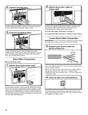
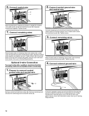
...through the hole (B) below . The strain relief should have 5 ft. (1.52 m) of extra length so dryer may be in a horizontal position. Connect remaining wires to Venting Requirements. Finally, reinsert tab of dryer rear panel. Direct Wire Connection Direct wire strain relief 1. Cut 11/2" (38 mm) from a 3/4" ...wire BC 2. Strip insulation back 1" (25 mm). For 3-wire Direct Wire Connection, see page 11. Tighten screw. 5. Secure cover with the dryer cabinet and be moved if needed. Now, go to outer terminal block screws. Strip 5" (127 mm) of outer covering from end of power ...
...through the hole (B) below . The strain relief should have 5 ft. (1.52 m) of extra length so dryer may be in a horizontal position. Connect remaining wires to Venting Requirements. Finally, reinsert tab of dryer rear panel. Direct Wire Connection Direct wire strain relief 1. Cut 11/2" (38 mm) from a 3/4" ...wire BC 2. Strip insulation back 1" (25 mm). For 3-wire Direct Wire Connection, see page 11. Tighten screw. 5. Secure cover with the dryer cabinet and be moved if needed. Now, go to outer terminal block screws. Strip 5" (127 mm) of outer covering from end of power ...
Installation Guide
Page 11
...of neutral wire (white or center wire) (C) of direct wire cable under terminal block screw, facing to terminal block, place hooked end of dryer rear panel. Squeeze hooked ends together and tighten screws. Prepare your 3-wire cable for direct connection (251"mm) (893m½m" ) Direct... covering from external ground conductor screw (A). 6. Tighten screw. Shape wire ends into slot of wire under center screw of extra length so dryer may be moved if needed. 5. Secure cover with outer covering. Now, go to Venting Requirements. 3-wire Direct Wire Connection Use where ...
...of neutral wire (white or center wire) (C) of direct wire cable under terminal block screw, facing to terminal block, place hooked end of dryer rear panel. Squeeze hooked ends together and tighten screws. Prepare your 3-wire cable for direct connection (251"mm) (893m½m" ) Direct... covering from external ground conductor screw (A). 6. Tighten screw. Shape wire ends into slot of wire under center screw of extra length so dryer may be moved if needed. 5. Secure cover with outer covering. Now, go to Venting Requirements. 3-wire Direct Wire Connection Use where ...
Installation Guide
Page 12
... terminal block screw (B). Connect external ground wire 1. Finally, reinsert tab of terminal block cover into slot of dryer rear panel. Squeeze hooked end together. Finally, reinsert tab of terminal block cover into slot of dryer rear panel. Place hooked ends of direct wire cable under outer terminal block screws (hooks facing right...
... terminal block screw (B). Connect external ground wire 1. Finally, reinsert tab of terminal block cover into slot of dryer rear panel. Squeeze hooked end together. Finally, reinsert tab of terminal block cover into slot of dryer rear panel. Place hooked ends of direct wire cable under outer terminal block screws (hooks facing right...

Installation Guide
Page 13
... or metal foil vents with rigid metal or flexible metal vents. Only rigid or flexible metal vent shall be fully extended and supported in final dryer location. ■■ Remove excess to clean) ■■ Must be used . ■■ Do not use duct tape. Recommended Styles...: Louvered hood Acceptable Style: Box hood WARNING: To reduce the risk of fire, this dryer MUST BE EXHAUSTED OUTDOORS. Flexible metal vent: (Acceptable only if accessible to avoid sagging and kinking that may result in reduced airflow and poor ...
... or metal foil vents with rigid metal or flexible metal vents. Only rigid or flexible metal vent shall be fully extended and supported in final dryer location. ■■ Remove excess to clean) ■■ Must be used . ■■ Do not use duct tape. Recommended Styles...: Louvered hood Acceptable Style: Box hood WARNING: To reduce the risk of fire, this dryer MUST BE EXHAUSTED OUTDOORS. Flexible metal vent: (Acceptable only if accessible to avoid sagging and kinking that may result in reduced airflow and poor ...
Installation Guide
Page 14
... are available for purchase. Two close elbow 4396007RW Through-the-wall vent cap 4396008RP 4" steel dryer venting clamps - 2 pack 8212662 Flush mounting louvered vent hood 4" 14 Exhaust outlet Over-The-Top installation (also available... (over-the-top installation) 4396009RP 5' Universal connect vent, flexible dryer venting 4396010RP 6' SecureConnect™ vent, flexible dryer venting 4396013RB Dryer vent installer's kit 4396033RP 5' flexible dryer venting with clamps 4396727RP 8' flexible dryer venting with one offset elbow) Periscope installation NOTE: The following kits...
... are available for purchase. Two close elbow 4396007RW Through-the-wall vent cap 4396008RP 4" steel dryer venting clamps - 2 pack 8212662 Flush mounting louvered vent hood 4" 14 Exhaust outlet Over-The-Top installation (also available... (over-the-top installation) 4396009RP 5' Universal connect vent, flexible dryer venting 4396010RP 6' SecureConnect™ vent, flexible dryer venting 4396013RB Dryer vent installer's kit 4396033RP 5' flexible dryer venting with clamps 4396727RP 8' flexible dryer venting with one offset elbow) Periscope installation NOTE: The following kits...
Installation Guide
Page 15
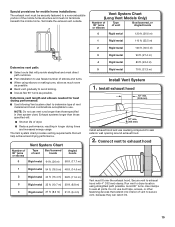
...vent must be securely fastened to seal exterior wall opening around exhaust hood. 2. Vent System Chart Number of 90° turns or elbows Type of dryer. ■■ Reduce performance, resulting in Vent system chart. Use clamps to use fewest number of vent to avoid kinking. ■■ Use...; Use following Vent system chart to determine type of the mobile home structure and must not terminate beneath the mobile home. Run vent to dryer location using elbows or making turns, allow as much room as possible. ■■ Bend vent gradually to secure vent, because they can...
...vent must be securely fastened to seal exterior wall opening around exhaust hood. 2. Vent System Chart Number of 90° turns or elbows Type of dryer. ■■ Reduce performance, resulting in Vent system chart. Use clamps to use fewest number of vent to avoid kinking. ■■ Use...; Use following Vent system chart to determine type of the mobile home structure and must not terminate beneath the mobile home. Run vent to dryer location using elbows or making turns, allow as much room as possible. ■■ Bend vent gradually to secure vent, because they can...

Installation Guide
Page 16
...to exhaust hood with a damp cloth to back. q For power supply cord installation, plug into an outlet and/or electrical supply is in dryer. q Wipe dryer drum interior thoroughly with a 4" (102 mm) clamp. 2. q Check that you have all four legs are now installed. Complete Installation ... ■■ Controls are set in your tools. Once legs are level, make sure vent is level. Dryer vent must be level for levelness. Level Dryer 1. Level Dryer Check levelness of /recycle all parts are snug against the ground before tightening them. Be sure vent is closed...
...to exhaust hood with a damp cloth to back. q For power supply cord installation, plug into an outlet and/or electrical supply is in dryer. q Wipe dryer drum interior thoroughly with a 4" (102 mm) clamp. 2. q Check that you have all four legs are now installed. Complete Installation ... ■■ Controls are set in your tools. Once legs are level, make sure vent is level. Dryer vent must be level for levelness. Level Dryer 1. Level Dryer Check levelness of /recycle all parts are snug against the ground before tightening them. Be sure vent is closed...

Installation Guide
Page 17
...lift to separate it from hinges Place towel on top of hinges. NOTE: Magnetized screw driver is first used. q When the dryer has been running for 5 minutes, open the dryer door and feel heat, cancel cycle and close the door. Remove screws at top, bottom, and side of hinge slot. ...: Do not pry apart with putty knife or screwdriver. Remove top screws from door Open dryer door. Remove screws from inner door. Remove bottom screws from dryer cabinet side of dryer. Loosen (do not feel heat, turn off dryer, and check the following: ■■ There may notice an odor when the...
...lift to separate it from hinges Place towel on top of hinges. NOTE: Magnetized screw driver is first used. q When the dryer has been running for 5 minutes, open the dryer door and feel heat, cancel cycle and close the door. Remove screws at top, bottom, and side of hinge slot. ...: Do not pry apart with putty knife or screwdriver. Remove top screws from door Open dryer door. Remove screws from inner door. Remove bottom screws from dryer cabinet side of dryer. Loosen (do not feel heat, turn off dryer, and check the following: ■■ There may notice an odor when the...
Installation Guide
Page 18
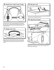
..., bezel, & plug Catch and bezel Plug 8. Attach door hinges Remove the door catch, bezel, and plug from where they were. 7. Reattach outer door panel to dryer door so that the larger hole is at the bottom of the inner door by squeezing and pulling/pushing them. Insert 4 door screws.
..., bezel, & plug Catch and bezel Plug 8. Attach door hinges Remove the door catch, bezel, and plug from where they were. 7. Reattach outer door panel to dryer door so that the larger hole is at the bottom of the inner door by squeezing and pulling/pushing them. Insert 4 door screws.

Installation Guide
Page 19
...11. 10. Insert the door strike into original door strike hole and secure with screw. Insert screws into hinge holes on left side of dryer cabinet. Tighten screws. Insert and tighten top screws in hinge holes on left or right within slot to gently remove 4 hinge hole plugs...Close door and check that door strike aligns with door catch. Transfer plugs into the bottom holes on dryer cabinet Door strike Door strike plug Remove door strike and door strike plug from dryer cabinet. If it is over screws. Insert screws in hinges. 13. Check door strike alignment Use ...
...11. 10. Insert the door strike into original door strike hole and secure with screw. Insert screws into hinge holes on left side of dryer cabinet. Tighten screws. Insert and tighten top screws in hinge holes on left or right within slot to gently remove 4 hinge hole plugs...Close door and check that door strike aligns with door catch. Transfer plugs into the bottom holes on dryer cabinet Door strike Door strike plug Remove door strike and door strike plug from dryer cabinet. If it is over screws. Insert screws in hinges. 13. Check door strike alignment Use ...

Specification Sheet
Page 1
.../16" 64' Rear Only No NOTE: Dimensions are for planning purposes only. Electric Dryer NED4655E Capacity Total 6.5 cu. All rights reserved. General Features & Properties 11 Dryer Cycles Reversible Door Electrical Details Hz 60 Amps 30 Volts 240 White NED4655EW Key Features & Benefits Automatic Dryness Control Automatic Dryness Control uses temperature sensors to end...
.../16" 64' Rear Only No NOTE: Dimensions are for planning purposes only. Electric Dryer NED4655E Capacity Total 6.5 cu. All rights reserved. General Features & Properties 11 Dryer Cycles Reversible Door Electrical Details Hz 60 Amps 30 Volts 240 White NED4655EW Key Features & Benefits Automatic Dryness Control Automatic Dryness Control uses temperature sensors to end...


