
User Guide
Page 13
ASUS RS920A-E6/RS8; RS924-E6/RS8 1- It includes sections on front panel and rear panel specifications. Product introduction Chapter 1 This chapter describes the general features of the chassis kit.
ASUS RS920A-E6/RS8; RS924-E6/RS8 1- It includes sections on front panel and rear panel specifications. Product introduction Chapter 1 This chapter describes the general features of the chassis kit.
User Guide
Page 15
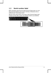
See the figure below. RS924A-E6/RS8 1-3 1.2 Serial number label Before requesting support from the ASUS Technical Support team, you must take note of the product, ASUS Technical Support team members can then offer a quicker and satisfying solution to your problems. RS924A -E6/RS8 xxS0xxxxxxxxxx ASUS RS920A-E6/RS8; With the correct serial number of the product's serial number containing 14 characters such as xxS0xxxxxxxxxx.
See the figure below. RS924A-E6/RS8 1-3 1.2 Serial number label Before requesting support from the ASUS Technical Support team, you must take note of the product, ASUS Technical Support team members can then offer a quicker and satisfying solution to your problems. RS924A -E6/RS8 xxS0xxxxxxxxxx ASUS RS920A-E6/RS8; With the correct serial number of the product's serial number containing 14 characters such as xxS0xxxxxxxxxx.

User Guide
Page 16
... H/W RAID card (continued on the next page) 1-4 Chapter 1: Product introduction Supports software RAID 0, 1, 5 & 10 Optional: PIKE riser is necessary. 1.3 System specifications The ASUS RS920A-E6/RS8 and RS924A-E6/RS8 are a servers featuring the ASUS KGPX-Q32 Series server board.The server supports AMD® LGA 1944 Opteron™ 6100 series and 6200 series processors with ECC...
... H/W RAID card (continued on the next page) 1-4 Chapter 1: Product introduction Supports software RAID 0, 1, 5 & 10 Optional: PIKE riser is necessary. 1.3 System specifications The ASUS RS920A-E6/RS8 and RS924A-E6/RS8 are a servers featuring the ASUS KGPX-Q32 Series server board.The server supports AMD® LGA 1944 Opteron™ 6100 series and 6200 series processors with ECC...

User Guide
Page 17
ASUS RS920A-E6/RS8; HDD Bays I = Internal A or S will be hot-swappable Networking LAN Graphic VGA Auxiliary Storage Device Bay (Floppy / Optical Device) Onboard I/O OS Support Anti-virus Software ...°C-35°C / Non operation temperature: -40°C-70°C Non operation humidity:20%-90% ( Non-condensing) *Specifications are subject to change without notice. RS924A-E6/RS8 1-5
ASUS RS920A-E6/RS8; HDD Bays I = Internal A or S will be hot-swappable Networking LAN Graphic VGA Auxiliary Storage Device Bay (Floppy / Optical Device) Onboard I/O OS Support Anti-virus Software ...°C-35°C / Non operation temperature: -40°C-70°C Non operation humidity:20%-90% ( Non-condensing) *Specifications are subject to change without notice. RS924A-E6/RS8 1-5

User Guide
Page 19
...to the front cover before turning on the system for proper heat dissipation. *WARNING HAZARDOUS MOVING PARTS KEEP FINGERS AND OTHER BODY PARTS AWAY ASUS RS920A-E6/RS8; Hot-swap HDD tray 1- 8 (SAS and SATA) 6. Slim-type optical drive bay 7. Front I/O board (hidden) 8. Please remove... (hidden) 2 5. Redundant Power 1 supply and power fan (hidden) 8 8 2. A protection film is pre-attached to use a floppy disk. ASUS KGPX-Q32 Server Board 3. 8056 System fans 4. RS924A-E6/RS8 1-7 PIKE Slot 4 5 6 7 The barebone server does not include a floppy disk drive.
...to the front cover before turning on the system for proper heat dissipation. *WARNING HAZARDOUS MOVING PARTS KEEP FINGERS AND OTHER BODY PARTS AWAY ASUS RS920A-E6/RS8; Hot-swap HDD tray 1- 8 (SAS and SATA) 6. Slim-type optical drive bay 7. Front I/O board (hidden) 8. Please remove... (hidden) 2 5. Redundant Power 1 supply and power fan (hidden) 8 8 2. A protection film is pre-attached to use a floppy disk. ASUS KGPX-Q32 Server Board 3. 8056 System fans 4. RS924A-E6/RS8 1-7 PIKE Slot 4 5 6 7 The barebone server does not include a floppy disk drive.

User Guide
Page 21
RS924A-E6/RS8 1-9 1.7.2 LAN (RJ-45) LEDs LAN5 LEDs ACT/LINK LED Status Description OFF No link GREEN Linked ACT/LINK LED SPEED LED SPEED LED Status Description OFF 10 Mbps connection ORANGE 100 Mbps connection LAN1 to LAN4 LEDs ACT/LINK LED Status Description OFF No link GREEN Linked BLINKING Data activity ACT/LINK LED SPEED LED SPEED LED Status Description OFF 10 Mbps connection ORANGE 100 Mbps connection GREEN 1 Gbps connection ASUS RS920A-E6/RS8;
RS924A-E6/RS8 1-9 1.7.2 LAN (RJ-45) LEDs LAN5 LEDs ACT/LINK LED Status Description OFF No link GREEN Linked ACT/LINK LED SPEED LED SPEED LED Status Description OFF 10 Mbps connection ORANGE 100 Mbps connection LAN1 to LAN4 LEDs ACT/LINK LED Status Description OFF No link GREEN Linked BLINKING Data activity ACT/LINK LED SPEED LED SPEED LED Status Description OFF 10 Mbps connection ORANGE 100 Mbps connection GREEN 1 Gbps connection ASUS RS920A-E6/RS8;

User Guide
Page 23
RS924-E6/RS8 2- ASUS RS920A-E6/RS8; Hardware setup Chapter 2 This chapter lists the hardware setup procedures that you have to perform when installing or removing system components.
RS924-E6/RS8 2- ASUS RS920A-E6/RS8; Hardware setup Chapter 2 This chapter lists the hardware setup procedures that you have to perform when installing or removing system components.

User Guide
Page 25
ASUS will shoulder the cost of repair only if the damage is on your left. Before installing the CPU, ensure that the PnP cap is shipment/transit-related. • Keep the cap after installing the motherboard. RS924A-E6/RS8 2-3 If the instructions in this section do not match the CPU ... CPU socket on the LGA1944 socket. • The product warranty does not cover damage to the PnP cap/socket contacts/motherboard components. ASUS RS920A-E6/RS8; 2.2 Central Processing Unit (CPU) The motherboard comes with four surface mount LGA1944 sockets designed for the CPU and heatsink.
ASUS will shoulder the cost of repair only if the damage is on your left. Before installing the CPU, ensure that the PnP cap is shipment/transit-related. • Keep the cap after installing the motherboard. RS924A-E6/RS8 2-3 If the instructions in this section do not match the CPU ... CPU socket on the LGA1944 socket. • The product warranty does not cover damage to the PnP cap/socket contacts/motherboard components. ASUS RS920A-E6/RS8; 2.2 Central Processing Unit (CPU) The motherboard comes with four surface mount LGA1944 sockets designed for the CPU and heatsink.

User Guide
Page 27
Some heatsinks come with , ensuring that it snaps into F the retention tab. ASUS RS920A-E6/RS8; G CPU Installation Sequence: CPU1 Configuration CPU1 Socket CPU2 Socket One Processor V Dual Processors V V Quad Processors V V CPU3 Socket CPU3 Socket V V Apply some Thermal Interface Material to the exposed area of the CPU that the heatsink will be in an even thin layer. If so, skip this step. 7. RS924A-E6/RS8 2-5 Close the load plate (F), then push the load lever (G) until it is spread in contact with pre-applied Thermal Interface Material.
Some heatsinks come with , ensuring that it snaps into F the retention tab. ASUS RS920A-E6/RS8; G CPU Installation Sequence: CPU1 Configuration CPU1 Socket CPU2 Socket One Processor V Dual Processors V V Quad Processors V V CPU3 Socket CPU3 Socket V V Apply some Thermal Interface Material to the exposed area of the CPU that the heatsink will be in an even thin layer. If so, skip this step. 7. RS924A-E6/RS8 2-5 Close the load plate (F), then push the load lever (G) until it is spread in contact with pre-applied Thermal Interface Material.

User Guide
Page 29
... E1 F2 F1 G2 G1 H2 H1 2 DIMMs V V 4 DIMMs V V V V 6 DIMMs V V V V V V 8 DIMMs V V V V V V V V 10 DIMMs V V V V V VVV V V 12 DIMMs V V V VVV VVV VVV 14 DIMMs V V V V V V V VVVVV V V 16 DIMMs V V V V V V V V V V V V V V V V ASUS RS920A-E6/RS8; RS924A-E6/RS8 2-7 2.3 System memory 2.3.1 Overview The motherboard comes with ECC/Non-ECC DDR3 DIMMs into the DIMM sockets using the memory configurations in this section. The figure...
... E1 F2 F1 G2 G1 H2 H1 2 DIMMs V V 4 DIMMs V V V V 6 DIMMs V V V V V V 8 DIMMs V V V V V V V V 10 DIMMs V V V V V VVV V V 12 DIMMs V V V VVV VVV VVV 14 DIMMs V V V V V V V VVVVV V V 16 DIMMs V V V V V V V V V V V V V V V V ASUS RS920A-E6/RS8; RS924A-E6/RS8 2-7 2.3 System memory 2.3.1 Overview The motherboard comes with ECC/Non-ECC DDR3 DIMMs into the DIMM sockets using the memory configurations in this section. The figure...
User Guide
Page 31
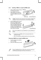
... any further to unlock the DIMM. 2. Hold the DIMM by pressing DIMM notch the retaining clip outward. 2. Remove the DIMM from a single clip DIMM socket 1. ASUS RS920A-E6/RS8; Align a DIMM on the socket such that it flips out with a notch so that the notch on the DIMM matches the DIMM slot key on...
... any further to unlock the DIMM. 2. Hold the DIMM by pressing DIMM notch the retaining clip outward. 2. Remove the DIMM from a single clip DIMM socket 1. ASUS RS920A-E6/RS8; Align a DIMM on the socket such that it flips out with a notch so that the notch on the DIMM matches the DIMM slot key on...
User Guide
Page 33
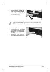
Repeat steps 1 to 6 if you wish to the SATAII/ SAS interface on the backplane. 6. When installed, the SATAII/SAS connector on the drive connects to install a second SATAII/SAS drive. ASUS RS920A-E6/RS8; The drive tray is correctly placed when its front edge aligns with the bay edge. 7. 5. RS924A-E6/RS8 2-11 Push the tray lever until it all the way to the depth of the bay until just a small fraction of the tray edge protrudes. Carefully insert the drive tray and push it clicks, and secures the drive tray in place.
Repeat steps 1 to 6 if you wish to the SATAII/ SAS interface on the backplane. 6. When installed, the SATAII/SAS connector on the drive connects to install a second SATAII/SAS drive. ASUS RS920A-E6/RS8; The drive tray is correctly placed when its front edge aligns with the bay edge. 7. 5. RS924A-E6/RS8 2-11 Push the tray lever until it all the way to the depth of the bay until just a small fraction of the tray edge protrudes. Carefully insert the drive tray and push it clicks, and secures the drive tray in place.
User Guide
Page 35
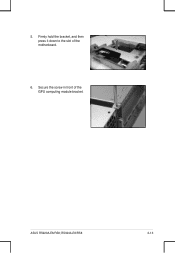
RS924A-E6/RS8 2-13 ASUS RS920A-E6/RS8; Secure the screw in front of the motherboard. 6. Firmly hold the bracket, and then press it down to the slot of the GPU computing module bracket. 5.
RS924A-E6/RS8 2-13 ASUS RS920A-E6/RS8; Secure the screw in front of the motherboard. 6. Firmly hold the bracket, and then press it down to the slot of the GPU computing module bracket. 5.

User Guide
Page 37
Power Supply SMBUS connector 6. SATA connectors (from motherboard to SATAII/SAS backplane board) 10. RS924A-E6/RS8 2-15 SGPIO 1,2 (Promise RAID) 11. SGPIO 3,4 (LSI PIKE RAID) ASUS RS920A-E6/RS8; SAS connector (from motherboard to front I /O board) 5. 2.6 Cable connections • The bundled system cables are pre-connected before shipment. Auxiliary Panel connector (from motherboard to ...
Power Supply SMBUS connector 6. SATA connectors (from motherboard to SATAII/SAS backplane board) 10. RS924A-E6/RS8 2-15 SGPIO 1,2 (Promise RAID) 11. SGPIO 3,4 (LSI PIKE RAID) ASUS RS920A-E6/RS8; SAS connector (from motherboard to front I /O board) 5. 2.6 Cable connections • The bundled system cables are pre-connected before shipment. Auxiliary Panel connector (from motherboard to ...
User Guide
Page 39
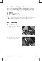
... any components. 2.8.1 System fans To uninstall the system fans 1. This section tells how to install the optional components into the system. ASUS RS920A-E6/RS8; Redundant power supply units 3. ASUS PIKE RAID card (optional) 4. RS924A-E6/RS8 2-17 System fans 2. Carefully remove the system fan cable from the fan connector on the motherboard. 2. 2.8 Removable/optional components You...
... any components. 2.8.1 System fans To uninstall the system fans 1. This section tells how to install the optional components into the system. ASUS RS920A-E6/RS8; Redundant power supply units 3. ASUS PIKE RAID card (optional) 4. RS924A-E6/RS8 2-17 System fans 2. Carefully remove the system fan cable from the fan connector on the motherboard. 2. 2.8 Removable/optional components You...
User Guide
Page 41
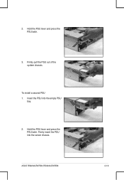
To install a second PSU 1. Firmly pull the PSU out of the system chassis. Hold the PSU lever and press the PSU latch. Firmly insert the PSU into the empty PSU bay. 2. RS924A-E6/RS8 2-19 2. Hold the PSU lever and press the PSU latch. 3. ASUS RS920A-E6/RS8; Insert the PSU into the server chassis.
To install a second PSU 1. Firmly pull the PSU out of the system chassis. Hold the PSU lever and press the PSU latch. Firmly insert the PSU into the empty PSU bay. 2. RS924A-E6/RS8 2-19 2. Hold the PSU lever and press the PSU latch. 3. ASUS RS920A-E6/RS8; Insert the PSU into the server chassis.

User Guide
Page 43
...Unit in place. Heatsink bracket 2. Remove the two screws that secure the heatsink bracket on the back of the SAS RAID card. RS924A-E6/RS8 2-21 Remove the two screws that secure the outer heatsink on the front of the SAS RAID card. Connect one end of the cable... install the PIKE 2108 Series SAS RAID card, follow steps 1 and 2 to install an optional ASUS RAID card on your motherboard. Slide the rest of the cable to the Battery Backup Unit. 4. ASUS RS920A-E6/RS8; 2.8.3 Installing ASUS PIKE RAID card (optional) Follow the steps below to remove the outer heatsink on RAID card....
...Unit in place. Heatsink bracket 2. Remove the two screws that secure the heatsink bracket on the back of the SAS RAID card. RS924A-E6/RS8 2-21 Remove the two screws that secure the outer heatsink on the front of the SAS RAID card. Connect one end of the cable... install the PIKE 2108 Series SAS RAID card, follow steps 1 and 2 to install an optional ASUS RAID card on your motherboard. Slide the rest of the cable to the Battery Backup Unit. 4. ASUS RS920A-E6/RS8; 2.8.3 Installing ASUS PIKE RAID card (optional) Follow the steps below to remove the outer heatsink on RAID card....

User Guide
Page 45
Remove the SGPIO cable from the SGPIO3 connector on the motherboard. 6. ASUS RS920A-E6/RS8; Connect the data cables, by numerial order, to the SATA connectors on the motherboard. 5. 4. RS924A-E6/RS8 2-23 Remove the data cables connected to the SAS connectors labeled SAS1-4 (Blue) on the motherboard.
Remove the SGPIO cable from the SGPIO3 connector on the motherboard. 6. ASUS RS920A-E6/RS8; Connect the data cables, by numerial order, to the SATA connectors on the motherboard. 5. 4. RS924A-E6/RS8 2-23 Remove the data cables connected to the SAS connectors labeled SAS1-4 (Blue) on the motherboard.

User Guide
Page 49
... want to fit the depth of the front mounting hole, as shown in the right figure. 4. 1. Adjust the rack rail to install the rack rail. ASUS RS920A-E6/RS8; RS924A-E6/RS8 3-3 Secure the front and rear ends of the rail with two thin lips on the bottom thin lip of the rack. 3.
... want to fit the depth of the front mounting hole, as shown in the right figure. 4. 1. Adjust the rack rail to install the rack rail. ASUS RS920A-E6/RS8; RS924A-E6/RS8 3-3 Secure the front and rear ends of the rail with two thin lips on the bottom thin lip of the rack. 3.
User Guide
Page 51
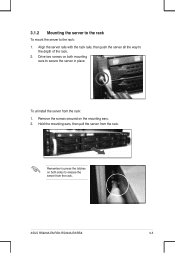
Remove the screws secured on both mounting ears to release the server from the rack. Hold the mounting ears, then pull the server from the rack: 1. Align the server rails with the rack rails, then push the server all the way to the rack: 1. ASUS RS920A-E6/RS8; To uninstall the server from the rack. RS924A-E6/RS8 3-5 Drive two screws on both sides to secure the server in place. Remember to press the latches on the mounting ears. 2. 3.1.2 Mounting the server to the rack To mount the server to the depth of the rack. 2.
Remove the screws secured on both mounting ears to release the server from the rack. Hold the mounting ears, then pull the server from the rack: 1. Align the server rails with the rack rails, then push the server all the way to the rack: 1. ASUS RS920A-E6/RS8; To uninstall the server from the rack. RS924A-E6/RS8 3-5 Drive two screws on both sides to secure the server in place. Remember to press the latches on the mounting ears. 2. 3.1.2 Mounting the server to the rack To mount the server to the depth of the rack. 2.


