User Manual
Page 2
... a retrieval system or translated into the specific cleaner for cleaning. Do not use liquid cleaners or aerosol cleaners. Use a clean, soft and cotton-free dry cloth to clean the panel. 7. Proper care will also prolong the service life of the panel. Unplug this User's Manual. Retain instructions - Water and moisture - Do not place the display on the product and in an...
... a retrieval system or translated into the specific cleaner for cleaning. Do not use liquid cleaners or aerosol cleaners. Use a clean, soft and cotton-free dry cloth to clean the panel. 7. Proper care will also prolong the service life of the panel. Unplug this User's Manual. Retain instructions - Water and moisture - Do not place the display on the product and in an...
User Manual
Page 3
... mounting the product on a wall, be walked on an unstable trolley, stand, pedestal, bracket, or table. Careful move - Sudden stops, excessive force and uneven floor surfaces can break when the display is made of service or repair work by small animals. Therefore, it must be routed so that the product needs servicing. 17. Pay particular attention to the manufacturer's instructions, and use attachments...
... mounting the product on a wall, be walked on an unstable trolley, stand, pedestal, bracket, or table. Careful move - Sudden stops, excessive force and uneven floor surfaces can break when the display is made of service or repair work by small animals. Therefore, it must be routed so that the product needs servicing. 17. Pay particular attention to the manufacturer's instructions, and use attachments...
User Manual
Page 4
..., green or red. Please note that this television equipment during a lightning storm, or when it is grounded so as to keep from the wall outlet and disconnect the antenna. English 22. If an outside antenna system should be fatal. Pixel defect - Installation of important operating and maintenance (servicing) instructions in the vicinity of overhead power lines or other electric light or power circuits...
..., green or red. Please note that this television equipment during a lightning storm, or when it is grounded so as to keep from the wall outlet and disconnect the antenna. English 22. If an outside antenna system should be fatal. Pixel defect - Installation of important operating and maintenance (servicing) instructions in the vicinity of overhead power lines or other electric light or power circuits...
User Manual
Page 5
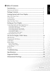
...Main Unit (Rear View 5 Setting up Your Display 6 Connecting Audio and Video Signal Sources 6 Connecting Composite (AV) Video Signals 6 Connecting S-Video Signals 7 Connecting Component Video Signals 7 Connecting RGB Signals (Mini D-SUB 8 Connecting DVI Signals...8 Connecting Audio Output Signals 9 Connecting the Power Cord 9 On-Screen Display (OSD) Menu 10 OSD Structure...10 Navigating the OSD Menu 11 Audio Menu ...11 Picture Menu ...12 Picture Mode Settings ...13 Selecting a Picture Mode...14 Feature Menu...14 PC Menu ...16 Troubleshooting 17 Specifications 18 Supported Modes 19...
...Main Unit (Rear View 5 Setting up Your Display 6 Connecting Audio and Video Signal Sources 6 Connecting Composite (AV) Video Signals 6 Connecting S-Video Signals 7 Connecting Component Video Signals 7 Connecting RGB Signals (Mini D-SUB 8 Connecting DVI Signals...8 Connecting Audio Output Signals 9 Connecting the Power Cord 9 On-Screen Display (OSD) Menu 10 OSD Structure...10 Navigating the OSD Menu 11 Audio Menu ...11 Picture Menu ...12 Picture Mode Settings ...13 Selecting a Picture Mode...14 Feature Menu...14 PC Menu ...16 Troubleshooting 17 Specifications 18 Supported Modes 19...
User Manual
Page 7
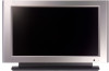
... you for purchasing the BenQ DV3750 LCD Display. Stereo / MTS sound 3. PC/DVI input signal auto calibration 6. Aspect ratio adjustment Introduction 1 Your DV3750 will explain the operation of high-quality viewing enjoyment. Before installing or operating your LCD display, please take the time to operate, and provides exceptionally high image quality. It is also extremely easy to thoroughly read this manual, particularly the sections on the wall (optional wall-mounting kit is also...
... you for purchasing the BenQ DV3750 LCD Display. Stereo / MTS sound 3. PC/DVI input signal auto calibration 6. Aspect ratio adjustment Introduction 1 Your DV3750 will explain the operation of high-quality viewing enjoyment. Before installing or operating your LCD display, please take the time to operate, and provides exceptionally high image quality. It is also extremely easy to thoroughly read this manual, particularly the sections on the wall (optional wall-mounting kit is also...
User Manual
Page 9
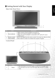
... standby mode. • Flashes red when the display is in order not to a PC and the PC enters standby mode. Name Description • Press this button to turn the display off by and put any objects in front of signals. 5 4 3 2 1 No. Receives the signal from the remote control. Getting Started with Your Display Main Unit (Front View) 1 2 No. Name 1 Power indicator 2 Remote control sensor window Control Panel Description • Lights up green when the display is powered...
... standby mode. • Flashes red when the display is in order not to a PC and the PC enters standby mode. Name Description • Press this button to turn the display off by and put any objects in front of signals. 5 4 3 2 1 No. Receives the signal from the remote control. Getting Started with Your Display Main Unit (Front View) 1 2 No. Name 1 Power indicator 2 Remote control sensor window Control Panel Description • Lights up green when the display is powered...

User Manual
Page 10
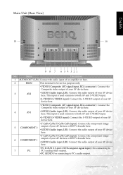
... connecting an external headset. 3 Subwoofer Allows you to switch among different input signal sources. • When the OSD (On-Screen Display) menu is on , press this button to exit the menu. 1 2 3 No. English 2 INPUT 3 Selection / button 4 Volume / button 5 MENU button Terminal Panel • This button allows you to connect the display to enter the submenu. Name Description • VIDEO (Composite (AV) signal input, RCA connector): Connect the Composite video output of your AV device here. • AUDIO(Audio input, L/R): Connect the audio output...
... connecting an external headset. 3 Subwoofer Allows you to switch among different input signal sources. • When the OSD (On-Screen Display) menu is on , press this button to exit the menu. 1 2 3 No. English 2 INPUT 3 Selection / button 4 Volume / button 5 MENU button Terminal Panel • This button allows you to connect the display to enter the submenu. Name Description • VIDEO (Composite (AV) signal input, RCA connector): Connect the Composite video output of your AV device here. • AUDIO(Audio input, L/R): Connect the audio output...
User Manual
Page 11
... or HDTV decoder here. 6 COMPONENT 1 • AUDIO (Audio input, L/R): Connect the audio output of your AV device here. Name Description 1 AUDIO OUT (L/R) Connect the audio input of an amplifier or here. 2 RS232 This terminal is used common to both AV and S-VIDEO input. • S-VIDEO (S-VIDEO input): Connect the S-VIDEO output of your AV device here. • VIDEO (Composite (AV) signal input, RCA connector): Connect the Composite video output of your AV device here. 4 AV1 • AUDIO (Audio input, L/R): Connect the audio output...
... or HDTV decoder here. 6 COMPONENT 1 • AUDIO (Audio input, L/R): Connect the audio output of your AV device here. Name Description 1 AUDIO OUT (L/R) Connect the audio input of an amplifier or here. 2 RS232 This terminal is used common to both AV and S-VIDEO input. • S-VIDEO (S-VIDEO input): Connect the S-VIDEO output of your AV device here. • VIDEO (Composite (AV) signal input, RCA connector): Connect the Composite video output of your AV device here. 4 AV1 • AUDIO (Audio input, L/R): Connect the audio output...
User Manual
Page 12
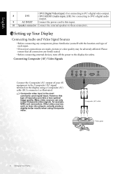
...disc players, actually produce slightly better results when using Composite video. Many video sources can only output Composite video signals, for safety. Composite (AV) cable Video game 6 Setting up Your Display Connecting Audio and Video Signal Sources • Before connecting any component, please familiarise yourself with the location and type of each input. • If incorrect connections are firmly seated. • Before connecting external devices, turn off the power to these connectors. English • DVI (Digital Video Input): For connecting to PC's digital video output...
...disc players, actually produce slightly better results when using Composite video. Many video sources can only output Composite video signals, for safety. Composite (AV) cable Video game 6 Setting up Your Display Connecting Audio and Video Signal Sources • Before connecting any component, please familiarise yourself with the location and type of each input. • If incorrect connections are firmly seated. • Before connecting external devices, turn off the power to these connectors. English • DVI (Digital Video Input): For connecting to PC's digital video output...
User Manual
Page 13
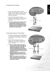
... equipment such as an HDTV decoder. 3. Connect the Component video output of the connector on progressive scan DVD players and Digital television decoders. Ensure the connector colors match, failure to that obtained with this input whenever possible. An S-video signal provides a higher quality image to connect the colors of Composite video. The image quality with S-video. Component Video Cable Audio (AV) cable DVD player Setting up Your Display 7 Connect the S-Video output of input is recommended to use this type of your AV...
... equipment such as an HDTV decoder. 3. Connect the Component video output of the connector on progressive scan DVD players and Digital television decoders. Ensure the connector colors match, failure to that obtained with this input whenever possible. An S-video signal provides a higher quality image to connect the colors of Composite video. The image quality with S-video. Component Video Cable Audio (AV) cable DVD player Setting up Your Display 7 Connect the S-Video output of input is recommended to use this type of your AV...
User Manual
Page 14
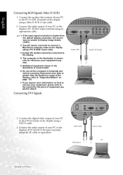
... to display image details clearly. 2. Do not set the computer's horizontal and vertical scanning frequencies less than or greater than the default display resolution, the screen may vary. 5. If you wish to the DVI terminal on the display using a Mini D-SUB 15-pin cable. 2. Audio cable DVD player DVI-D cable PC 8 Setting up Your Display Certain PC models cannot be unable to the display's DVI AUDIO L/R input terminals using a DVI-D cable. 2. Connect the digital video output of...
... to display image details clearly. 2. Do not set the computer's horizontal and vertical scanning frequencies less than or greater than the default display resolution, the screen may vary. 5. If you wish to the DVI terminal on the display using a Mini D-SUB 15-pin cable. 2. Audio cable DVD player DVI-D cable PC 8 Setting up Your Display Certain PC models cannot be unable to the display's DVI AUDIO L/R input terminals using a DVI-D cable. 2. Connect the digital video output of...
User Manual
Page 15
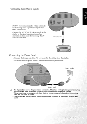
... the location where you purchased the display. • This product must be used for delivering audio signal to a wall power outlet. The shape of the physical power cord plug and socket will not be operated only from the wall outlet. As shown in the diagram, connect the male end to an amplifier or other audio devices using the AV cable or equivalent. Connect the AUDIO OUT L/R terminals on the display. 2. Setting...
... the location where you purchased the display. • This product must be used for delivering audio signal to a wall power outlet. The shape of the physical power cord plug and socket will not be operated only from the wall outlet. As shown in the diagram, connect the male end to an amplifier or other audio devices using the AV cable or equivalent. Connect the AUDIO OUT L/R terminals on the display. 2. Setting...
User Manual
Page 18
... Range 12 On-Screen Display (OSD) Menu Adjust image black level. for brighter blacks, for video inputs. Automatically adjusts the sound level to be constant Use the and buttons on the Steady Sound when viewing programs. remote control or the VOL and This option will become VOL buttons on the display to effect. Turn on or off SRS Use the and buttons on the SRS TS TruSurround XT Home remote control or the VOL...
... Range 12 On-Screen Display (OSD) Menu Adjust image black level. for brighter blacks, for video inputs. Automatically adjusts the sound level to be constant Use the and buttons on the Steady Sound when viewing programs. remote control or the VOL and This option will become VOL buttons on the display to effect. Turn on or off SRS Use the and buttons on the SRS TS TruSurround XT Home remote control or the VOL...
User Manual
Page 19
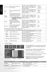
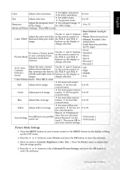
... • Warm: Biased toward blue - for PC input • Vivid To restore a factory preset Picture Mode or user customized user situation mode from the Picture menu to • To Personal 1 • To Personal 2 save your remote control or the MENU button on the display to enter. • Panel Default: backlight Use the and buttons color Adjust the color tint of the the VOL and VOL • Normal: Standard color image. Green Adjust green in image. Picture Mode Settings 1.
... • Warm: Biased toward blue - for PC input • Vivid To restore a factory preset Picture Mode or user customized user situation mode from the Picture menu to • To Personal 1 • To Personal 2 save your remote control or the MENU button on the display to enter. • Panel Default: backlight Use the and buttons color Adjust the color tint of the the VOL and VOL • Normal: Standard color image. Green Adjust green in image. Picture Mode Settings 1.

User Manual
Page 20
...- Selecting a Picture Mode 1. change selection. Press the or buttons to bring up , press the EXIT button on the remote control, or the MENU button on the display to select an item. 4. This option is activated. Item PIP Audio PBP Audio PIP & PBP* Function Operation Range Select which audio Use the and buttons source you want to hear. You can also press the PICTURE button on the display to close the menu. Press the MENU button to...
...- Selecting a Picture Mode 1. change selection. Press the or buttons to bring up , press the EXIT button on the remote control, or the MENU button on the display to select an item. 4. This option is activated. Item PIP Audio PBP Audio PIP & PBP* Function Operation Range Select which audio Use the and buttons source you want to hear. You can also press the PICTURE button on the display to close the menu. Press the MENU button to...
User Manual
Page 21
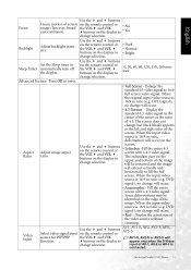
... a 4:3 video signal. Display the actual size of the image will be identified on the upper and bottom of the video source without zooming. on the remote control or the VOL and VOL buttons on the display to fill the full screen. Aspect Adjust image aspect Ratio ratio. • 4:3 Format - Video Input Use the and buttons Select video signal input on the display to Sleep Timer automatically turn off the display. Set the Sleep timer to change selection. DVD signal), no change , but black...
... a 4:3 video signal. Display the actual size of the image will be identified on the upper and bottom of the video source without zooming. on the remote control or the VOL and VOL buttons on the display to fill the full screen. Aspect Adjust image aspect Ratio ratio. • 4:3 Format - Video Input Use the and buttons Select video signal input on the display to Sleep Timer automatically turn off the display. Set the Sleep timer to change selection. DVD signal), no change , but black...

User Manual
Page 22
... signal formats. When receiving Component video signal in this function to the menu one level up the main menu. 2. Adjust display clock frequency. English Graphics Input Select graphics signal input source for PIP/ PBP function. Press the or buttons to select PC and then press OK to Settings default values. Use the and buttons on the remote control or the VOL and VOL buttons on the display to -32 to the display. 1. Reset All Restore all settings...
... signal formats. When receiving Component video signal in this function to the menu one level up the main menu. 2. Adjust display clock frequency. English Graphics Input Select graphics signal input source for PIP/ PBP function. Press the or buttons to select PC and then press OK to Settings default values. Use the and buttons on the remote control or the VOL and VOL buttons on the display to -32 to the display. 1. Reset All Restore all settings...
User Manual
Page 23
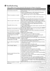
... whether the input signal is properly connected. Turn off the infrared function of the appear as black. There is no PC/DVI source signal. • The PC has been put to the display. Degraded colors or tints • Check whether all the picture adjustments have been properly performed. • Press the PICTURE button on the remote control. Power indicator lamp flashes red. • Check the PC/DVI cable for...
... whether the input signal is properly connected. Turn off the infrared function of the appear as black. There is no PC/DVI source signal. • The PC has been put to the display. Degraded colors or tints • Check whether all the picture adjustments have been properly performed. • Press the PICTURE button on the remote control. Power indicator lamp flashes red. • Check the PC/DVI cable for...
User Manual
Page 24
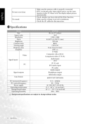
... Specifications No sound. • Make sure the antenna cable is properly connected. • If PC is selected as the input signal source, use the Auto function in the PC Menu to let the display adjust picture automatically. • Check whether you have selected the Mute function. • Make sure the volume is not clear. Specifications Model Size Aspect ratio Resolution Pitch Brightness Contrast ratio Viewing angle Response time Amplifier Signal inputs Video PC Signal outputs Scan format DV3750 94...
... Specifications No sound. • Make sure the antenna cable is properly connected. • If PC is selected as the input signal source, use the Auto function in the PC Menu to let the display adjust picture automatically. • Check whether you have selected the Mute function. • Make sure the volume is not clear. Specifications Model Size Aspect ratio Resolution Pitch Brightness Contrast ratio Viewing angle Response time Amplifier Signal inputs Video PC Signal outputs Scan format DV3750 94...
User Manual
Page 25
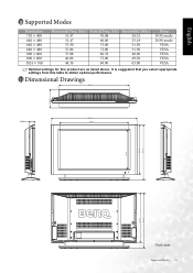
Dimensional Drawings Unit: mm Supported Modes 19 It is suggested that you select appropriate settings from this product are as listed above. English Supported Modes Resolution 720 × 400 640 × 480 640 × 480 640 × 480 800 × 600 800 × 600 1024 × 768 Horizontal Freq. (khz) Vertical ....86 72.80 31.50 37.88 60.32 40.00 46.86 75.00 49.50 48.36 60.00 65.00 Notes DOS mode DOS mode VESA VESA VESA VESA VESA Optimal settings for this table to obtain optimal performance.
Dimensional Drawings Unit: mm Supported Modes 19 It is suggested that you select appropriate settings from this product are as listed above. English Supported Modes Resolution 720 × 400 640 × 480 640 × 480 640 × 480 800 × 600 800 × 600 1024 × 768 Horizontal Freq. (khz) Vertical ....86 72.80 31.50 37.88 60.32 40.00 46.86 75.00 49.50 48.36 60.00 65.00 Notes DOS mode DOS mode VESA VESA VESA VESA VESA Optimal settings for this table to obtain optimal performance.


