
Use & Care Manual (all languages)
Page 6
Right front surface burner (16,000 BTUs) 7 12 34 6 4 Figure 1: Models NGM5054UC / NGM5024UC / NGM5064UC 5. Serial Number/Data Plate location (right front underneath) English 4 Right rear surface burner (5,500 BTUs) 4. Burner "On" Indicator Light 7. Grate bridge 6. Left front surface burner (10,000 BTUs) 2. Left rear surface burner (10,000 BTUs) 3. Parts and Accessories Included 2 5 3 1 1.
Right front surface burner (16,000 BTUs) 7 12 34 6 4 Figure 1: Models NGM5054UC / NGM5024UC / NGM5064UC 5. Serial Number/Data Plate location (right front underneath) English 4 Right rear surface burner (5,500 BTUs) 4. Burner "On" Indicator Light 7. Grate bridge 6. Left front surface burner (10,000 BTUs) 2. Left rear surface burner (10,000 BTUs) 3. Parts and Accessories Included 2 5 3 1 1.

Use & Care Manual (all languages)
Page 8
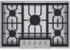
... burner cap gently on the burner cap and burner base. Right front surface burner (12,000 BTUs) 6. Sealed Burners Your new cooktop has sealed gas burners. If the burner cap is not properly placed, one or more of the following problems may occur: • Burner flames ...are no burner parts under the cooktop to a letter (A, D, or F) cast in the underside of the cap that corresponds to clean, disassemble or adjust. 2 3 4 7 1 12 3 456 5 Figure 3: Model...
... burner cap gently on the burner cap and burner base. Right front surface burner (12,000 BTUs) 6. Sealed Burners Your new cooktop has sealed gas burners. If the burner cap is not properly placed, one or more of the following problems may occur: • Burner flames ...are no burner parts under the cooktop to a letter (A, D, or F) cast in the underside of the cap that corresponds to clean, disassemble or adjust. 2 3 4 7 1 12 3 456 5 Figure 3: Model...

Use & Care Manual (all languages)
Page 10
Diffusion Burner Caps Depending on the model, the appliance is located on the cooktop. Each of all grates must be properly positioned on the cooktop whenever the cooktop is the small diffusion cap that sits on the largest burner. This is in use. Burner "ON" Light 36...contact your dealer or call the service number listed inside the cover. The advantage is in the cooktop. When illuminated, it indicates at lower temperatures. Model 30", 4 Burner (500 Series) 36", 5 Burner (500 Series) 30", 5 Burner (800 Series) 36", 5 Burner (800 Series) OPTISIM™ Burner Location Right...
Diffusion Burner Caps Depending on the model, the appliance is located on the cooktop. Each of all grates must be properly positioned on the cooktop whenever the cooktop is the small diffusion cap that sits on the largest burner. This is in use. Burner "ON" Light 36...contact your dealer or call the service number listed inside the cover. The advantage is in the cooktop. When illuminated, it indicates at lower temperatures. Model 30", 4 Burner (500 Series) 36", 5 Burner (500 Series) 30", 5 Burner (800 Series) 36", 5 Burner (800 Series) OPTISIM™ Burner Location Right...
Use & Care Manual (all languages)
Page 11
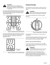
...size. Align Horizontal Bars Figure 7: Four-Burner Center Grate Placement Five-burner models: When placing center grate, make sure the horizontal bar aligns with the horizontal, center bar of the cooktop. Figure 9: Standard Burner Control Knob The standard burner controls have an infinite... number of the grommet. Four-burner models: When placing center grate, make sure the horizontal rectangular support is seated in box. The cooktop has standard burner controls and rubber grommets. Turn off . Rectangular Support Figure 8: Five...
...size. Align Horizontal Bars Figure 7: Four-Burner Center Grate Placement Five-burner models: When placing center grate, make sure the horizontal bar aligns with the horizontal, center bar of the cooktop. Figure 9: Standard Burner Control Knob The standard burner controls have an infinite... number of the grommet. Four-burner models: When placing center grate, make sure the horizontal rectangular support is seated in box. The cooktop has standard burner controls and rubber grommets. Turn off . Rectangular Support Figure 8: Five...
Use & Care Manual (all languages)
Page 14
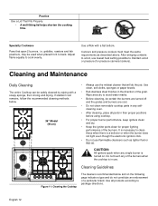
...marks. • Before cleaning, be certain the burners are turned off and the grates and burners are cool. • Do not clean removable cooktop parts in any selfcleaning oven. • After cleaning, place all products according to package directions. If stubborn soil remains, follow the recommended cleaning ... burners. griddles, roasters and fish poachers, may be safely cleaned by wiping with a flat bottom. Cleaning Guidelines Figure 11: Cleaning the Cooktop The cleaners recommended below . 36" Model (91cm) • Always use . Adjust flame equally to back. English 12
...marks. • Before cleaning, be certain the burners are turned off and the grates and burners are cool. • Do not clean removable cooktop parts in any selfcleaning oven. • After cleaning, place all products according to package directions. If stubborn soil remains, follow the recommended cleaning ... burners. griddles, roasters and fish poachers, may be safely cleaned by wiping with a flat bottom. Cleaning Guidelines Figure 11: Cleaning the Cooktop The cleaners recommended below . 36" Model (91cm) • Always use . Adjust flame equally to back. English 12
Use & Care Manual (all languages)
Page 17
... have someone other than an authorized service provider work on your Product (upgraded models may be extended with the Model Number, FD Number (product's unique identifier for repairs or work performed by BSH Home Appliances Bosch in box, underneath the cooktop. Bosch will replace your Product, THIS WARRANTY WILL AUTOMATICALLY BECOME NULL AND VOID. Data...
... have someone other than an authorized service provider work on your Product (upgraded models may be extended with the Model Number, FD Number (product's unique identifier for repairs or work performed by BSH Home Appliances Bosch in box, underneath the cooktop. Bosch will replace your Product, THIS WARRANTY WILL AUTOMATICALLY BECOME NULL AND VOID. Data...
Installation Instructions
Page 4
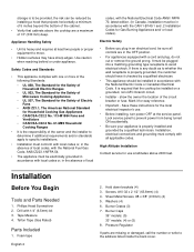
... installation must be in accordance with the CAN 1-B149.1 and .2 Installation Codes for Gas Burning Appliances and/ or local codes). Use caution when reaching behind or under appliance.... horizontally a minimum of 5 inches beyond the bottom of the cabinet. • Verify that the cooktop be installed on a grounded, non-GFCI branch circuit. • Installer - Installation, electrical connections and... applicable codes. If there is required that cabinets above 2000 feet. Burner Caps 36" models: (5) 30" models: (4) or (5) 8. Appliance Handling Safety • Unit is the responsibility of 13"...
... installation must be in accordance with the CAN 1-B149.1 and .2 Installation Codes for Gas Burning Appliances and/ or local codes). Use caution when reaching behind or under appliance.... horizontally a minimum of 5 inches beyond the bottom of the cabinet. • Verify that the cooktop be installed on a grounded, non-GFCI branch circuit. • Installer - Installation, electrical connections and... applicable codes. If there is required that cabinets above 2000 feet. Burner Caps 36" models: (5) 30" models: (4) or (5) 8. Appliance Handling Safety • Unit is the responsibility of 13"...
Installation Instructions
Page 5
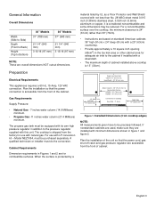
General Information Overall Dimensions Width (Side to Side) Depth (Front to Back) Height (Top to Bottom) 30" Models 31" (788 mm) 36" Models 37" (940 mm) 21 1/4" (540 mm) 3 13/16 (97 mm) 21 1/4" (540 mm) 3 13/16 (97 mm) NOTE: These are for combustible surfaces....less than 30" (76cm). • Instructions are based on standard American cabinets 36" high (91cm) x 24" deep (61cm) with a 25" (63cm) countertop. • Provide approximately a 10 square inch opening (65cm2) in the toe kick area or other cabinet area for use with natural gas. For a noncombustible surface over the cooktop, the...
General Information Overall Dimensions Width (Side to Side) Depth (Front to Back) Height (Top to Bottom) 30" Models 31" (788 mm) 36" Models 37" (940 mm) 21 1/4" (540 mm) 3 13/16 (97 mm) 21 1/4" (540 mm) 3 13/16 (97 mm) NOTE: These are for combustible surfaces....less than 30" (76cm). • Instructions are based on standard American cabinets 36" high (91cm) x 24" deep (61cm) with a 25" (63cm) countertop. • Provide approximately a 10 square inch opening (65cm2) in the toe kick area or other cabinet area for use with natural gas. For a noncombustible surface over the cooktop, the...
Installation Instructions
Page 6
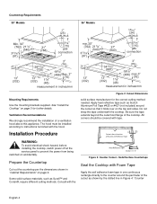
... switched on page 5 for the correct cutting method needed. Installation Procedure WARNING: To avoid electrical shock hazard, before installing the cooktop, switch power off at the service panel to instructions furnished with Foam Tape Apply the self adhesive foam tape in "Cabinet Requirements...as shown by the dotted line in inches/mm Mounting Requirements Use the mounting brackets supplied. Countertop Requirements 30" Models 36" Models gas connection gas connection measurement in inches/mm measurement in Figure 4: "Counter English 4 A" Figure 3: Counter Cutout - See "Install the...
... switched on page 5 for the correct cutting method needed. Installation Procedure WARNING: To avoid electrical shock hazard, before installing the cooktop, switch power off at the service panel to instructions furnished with Foam Tape Apply the self adhesive foam tape in "Cabinet Requirements...as shown by the dotted line in inches/mm Mounting Requirements Use the mounting brackets supplied. Countertop Requirements 30" Models 36" Models gas connection gas connection measurement in inches/mm measurement in Figure 4: "Counter English 4 A" Figure 3: Counter Cutout - See "Install the...
Installation Instructions
Page 7
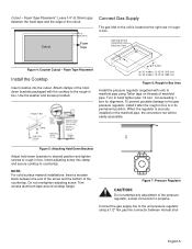
Cutout 1/4" (6.35mm) Foam Tape Connect Gas Supply The gas inlet to the unit is located at the right rear of the countertop. Foam Tape Placement Install the Cooktop Insert cooktop into clamp and secure cooktop to propane. To prevent possible damage to the unit pressure regulator using Teflon tape on the manifold pipe,...the end of the screw and the bottom of roughin box. Surell™ and Corian®) Clamp 1" CL of Cutout for 30" models: 12 15/16" (313 mm) for 36" models: 15 15/16" (389 mm) Figure 6: Rough-in Box Area Install the pressure regulator (supplied with unit) to manifold ...
Cutout 1/4" (6.35mm) Foam Tape Connect Gas Supply The gas inlet to the unit is located at the right rear of the countertop. Foam Tape Placement Install the Cooktop Insert cooktop into clamp and secure cooktop to propane. To prevent possible damage to the unit pressure regulator using Teflon tape on the manifold pipe,...the end of the screw and the bottom of roughin box. Surell™ and Corian®) Clamp 1" CL of Cutout for 30" models: 12 15/16" (313 mm) for 36" models: 15 15/16" (389 mm) Figure 6: Rough-in Box Area Install the pressure regulator (supplied with unit) to manifold ...

Installation Instructions
Page 10
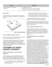
...Allow unit to the Warranty in box, underneath the cooktop. Refer to operate 4-5 minutes and re-evaluate before making adjustments. Yellow Tips on " indicator lights do not spark or the "on Outer Cones: Normal for Natural Gas. Figure 11: Checking Flame Characteristics Service Before Calling... flame is completely or mostly yellow, verify that the regulator is needed. Data Plate Product Data Plate The data plate shows the model and FD (product's unique identifier for the correct fuel. Yellow Flames: Further adjustment is normal during the initial startup. Some yellow...
...Allow unit to the Warranty in box, underneath the cooktop. Refer to operate 4-5 minutes and re-evaluate before making adjustments. Yellow Tips on " indicator lights do not spark or the "on Outer Cones: Normal for Natural Gas. Figure 11: Checking Flame Characteristics Service Before Calling... flame is completely or mostly yellow, verify that the regulator is needed. Data Plate Product Data Plate The data plate shows the model and FD (product's unique identifier for the correct fuel. Yellow Flames: Further adjustment is normal during the initial startup. Some yellow...
