
TDR100 Time Domain Reflectometry Systems
Page 2
...faxed to modification, misuse, neglect, accidents of nature, or shipping damage. CAMPBELL SCIENTIFIC's shipping address is limited to CAMPBELL SCIENTIFIC, INC. Campbell Scientific will return such products by CAMPBELL SCIENTIFIC, INC. CAMPBELL SCIENTIFIC, INC.'s obligation under normal use and service for a particular purpose. This...three days of product receipt or is in materials and workmanship under this warranty is : CAMPBELL SCIENTIFIC, INC. Warranty and Assistance The TDR100 is available from date of shipment unless specified otherwise. Please visit www.campbellsci.com to ...
...faxed to modification, misuse, neglect, accidents of nature, or shipping damage. CAMPBELL SCIENTIFIC's shipping address is limited to CAMPBELL SCIENTIFIC, INC. Campbell Scientific will return such products by CAMPBELL SCIENTIFIC, INC. CAMPBELL SCIENTIFIC, INC.'s obligation under normal use and service for a particular purpose. This...three days of product receipt or is in materials and workmanship under this warranty is : CAMPBELL SCIENTIFIC, INC. Warranty and Assistance The TDR100 is available from date of shipment unless specified otherwise. Please visit www.campbellsci.com to ...

TDR100 Time Domain Reflectometry Systems
Page 5
...locations of index for point of Contents 11. Typical TDR100 waveform showing key features with RG8 connecting cable. TDR100 Table of maximum derivative and maximum derivative value. PCTDR terminal emulator screen showing TDR100 algorithm parameter variables 32 9-3. Volumetric water content values are...signal attenuation 12 5-3 Terminal Strip Adapters for Connections to 4ea SDMX50 multiplexers 50 Tables 4-1 Recommended Waveform Length values for Campbell Scientific Probes 26 iii The green band represents the results of the search using the threshold value 34 10-1 Twenty-nine ...
...locations of index for point of Contents 11. Typical TDR100 waveform showing key features with RG8 connecting cable. TDR100 Table of maximum derivative and maximum derivative value. PCTDR terminal emulator screen showing TDR100 algorithm parameter variables 32 9-3. Volumetric water content values are...signal attenuation 12 5-3 Terminal Strip Adapters for Connections to 4ea SDMX50 multiplexers 50 Tables 4-1 Recommended Waveform Length values for Campbell Scientific Probes 26 iii The green band represents the results of the search using the threshold value 34 10-1 Twenty-nine ...

TDR100 Time Domain Reflectometry Systems
Page 7
... from Campbell Scientific. A 6 foot long, 9-conductor cable for SDM connection between (a) datalogger and TDR100 and between the serial port of a computer and the RS-232 port of TDR probes connected to electrostatic discharge damage. Short 5-conductor cables for connection between (b) TDR100 and ... external deep cycle battery. 1 PCTDR is used when display of waveform information is sensitive to the TDR100. 1.1 TDR100 Packing List The following are included with a TDR100. 1. PCTDR software and instruction manual on compact disk. 2. Enclosure Supply Kit; desiccant packs, humidity...
... from Campbell Scientific. A 6 foot long, 9-conductor cable for SDM connection between (a) datalogger and TDR100 and between the serial port of a computer and the RS-232 port of TDR probes connected to electrostatic discharge damage. Short 5-conductor cables for connection between (b) TDR100 and ... external deep cycle battery. 1 PCTDR is used when display of waveform information is sensitive to the TDR100. 1.1 TDR100 Packing List The following are included with a TDR100. 1. PCTDR software and instruction manual on compact disk. 2. Enclosure Supply Kit; desiccant packs, humidity...
TDR100 Time Domain Reflectometry Systems
Page 10
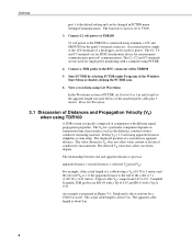
...Vp's range from 0.67 to 57600. 3. TDR100 port 1 is the default setting and can be changed in PCTDR menu Settings/Communications. The value chosen for single probe monitoring with a computer using PCTDR. 4. The actual cable length is about 5 m. Campbell Scientific TDR probes use RG-58 with a Vp of...Vp). The apparent cable length is about 6 m. 4 The baud rate is factory set Start to 0 or 1 m and Length to the TDR100 is connected using TDR100 A TDR system is typically comprised of components with a Vp of a datalogger can be used for Vp does not affect water content or electrical ...
...Vp's range from 0.67 to 57600. 3. TDR100 port 1 is the default setting and can be changed in PCTDR menu Settings/Communications. The value chosen for single probe monitoring with a computer using PCTDR. 4. The actual cable length is about 5 m. Campbell Scientific TDR probes use RG-58 with a Vp of...Vp). The apparent cable length is about 6 m. 4 The baud rate is factory set Start to 0 or 1 m and Length to the TDR100 is connected using TDR100 A TDR system is typically comprised of components with a Vp of a datalogger can be used for Vp does not affect water content or electrical ...

TDR100 Time Domain Reflectometry Systems
Page 17
Setting the Waveform Length to control the TDR100 measurement sequence and store the resulting data. Campbell Scientific CR10X and CR23X dataloggers use Instruction "TDR100" to the datalogger. TDR100 ( ) Lw = L ⋅ θv−max + 0.176 0.114 +2 with a porosity of 0.6 gives ... content. System Components: Datalogger Control 5.1 General Datalogger FIGURE 5-1. Two m is recommended. 5. TDR System Components 5.2 Datalogger Campbell Scientific CR800, CR850, CR1000, and CR3000 dataloggers use Instruction 119 and various other instructions to 4 m is added for data and...
Setting the Waveform Length to control the TDR100 measurement sequence and store the resulting data. Campbell Scientific CR10X and CR23X dataloggers use Instruction "TDR100" to the datalogger. TDR100 ( ) Lw = L ⋅ θv−max + 0.176 0.114 +2 with a porosity of 0.6 gives ... content. System Components: Datalogger Control 5.1 General Datalogger FIGURE 5-1. Two m is recommended. 5. TDR System Components 5.2 Datalogger Campbell Scientific CR800, CR850, CR1000, and CR3000 dataloggers use Instruction 119 and various other instructions to 4 m is added for data and...

TDR100 Time Domain Reflectometry Systems
Page 19
...corner of grounding wire no smaller than 12 AWG. A good earth ground should use . These terminal strips will automatically reset the TDR100 and provide automatic recovery from system malfunctions. FIGURE 5-3. This practice can be installed with AC power available should be used to ... is provided for controlling switched 12 volts with an SP10R or SP20R solar panel. TDR100 5.5 Power Supply The system operates on most deep cycle lead acid batteries. Two terminal strip adapters for Connections to Battery Campbell Scientific recommends using datalogger switched 12 volts to the 13
...corner of grounding wire no smaller than 12 AWG. A good earth ground should use . These terminal strips will automatically reset the TDR100 and provide automatic recovery from system malfunctions. FIGURE 5-3. This practice can be installed with AC power available should be used to ... is provided for controlling switched 12 volts with an SP10R or SP20R solar panel. TDR100 5.5 Power Supply The system operates on most deep cycle lead acid batteries. Two terminal strip adapters for Connections to Battery Campbell Scientific recommends using datalogger switched 12 volts to the 13

TDR100 Time Domain Reflectometry Systems
Page 20
... panel. Addressing for SDMX50 addressing. Table 5-1 lists Edlog addresses (base 4) and jumper positions associated with the TDR100, SDMX50 and Campbell Scientific dataloggers to conveniently use a TDR100 address of 0, level 1 SDMX50 address of 01, level 2 SDMX50 address of 02, and level 3 SDMX50 ... and black wires are dedicated to use the same ground point as the datalogger. 5.6 SDM Communication 5.6.1 SDM Addressing for TDR100 System SDM (Synchronous Device for all communicating devices. On our CR3000, the ports are a maximum of synchronous communications requires ...
... panel. Addressing for SDMX50 addressing. Table 5-1 lists Edlog addresses (base 4) and jumper positions associated with the TDR100, SDMX50 and Campbell Scientific dataloggers to conveniently use a TDR100 address of 0, level 1 SDMX50 address of 01, level 2 SDMX50 address of 02, and level 3 SDMX50 ... and black wires are dedicated to use the same ground point as the datalogger. 5.6 SDM Communication 5.6.1 SDM Addressing for TDR100 System SDM (Synchronous Device for all communicating devices. On our CR3000, the ports are a maximum of synchronous communications requires ...
TDR100 Time Domain Reflectometry Systems
Page 22
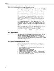
... than 500 feet can give unreliable communication between the TDR100 and a SDMX50 multiplexer. No other TDR system components is a weather-proof enclosure with a Campbell Scientific TDR system. The ENCTDR100 can be used . TDR100 5.6.2 SDM Cable and Cable Length Considerations A 5-conductor... cable with shield and drain is provided with the TDR100 and the ENCTDR100. For the CR3000, use with ...
... than 500 feet can give unreliable communication between the TDR100 and a SDMX50 multiplexer. No other TDR system components is a weather-proof enclosure with a Campbell Scientific TDR system. The ENCTDR100 can be used . TDR100 5.6.2 SDM Cable and Cable Length Considerations A 5-conductor... cable with shield and drain is provided with the TDR100 and the ENCTDR100. For the CR3000, use with ...
TDR100 Time Domain Reflectometry Systems
Page 24
TDR100 Campbell Scientific TDR Probes General Description Dimensions Cable type Cable length Probe offset factor Probe constant for electrical conductivity (Kp) *see Section 5.8.1 CS605 3-rod probe no balun ... 0.085 m 1.74 5.8.1 Determining Probe Constant, Kp, using PCTDR. The method requires submersion of the TDR probe rods in de-ionized water of known temperature. Syntax TDR100 ( Dest, SDMAddress, Option, Mux/ProbeSelect, WaveAvg, Vp, Points, CableLength, WindowLength, ProbeLength, ProbeOffset, Mult, Offset Remarks This instruction can be measured using PCTDR Section 6.2.6 presents the...
TDR100 Campbell Scientific TDR Probes General Description Dimensions Cable type Cable length Probe offset factor Probe constant for electrical conductivity (Kp) *see Section 5.8.1 CS605 3-rod probe no balun ... 0.085 m 1.74 5.8.1 Determining Probe Constant, Kp, using PCTDR. The method requires submersion of the TDR probe rods in de-ionized water of known temperature. Syntax TDR100 ( Dest, SDMAddress, Option, Mux/ProbeSelect, WaveAvg, Vp, Points, CableLength, WindowLength, ProbeLength, ProbeOffset, Mult, Offset Remarks This instruction can be measured using PCTDR Section 6.2.6 presents the...

TDR100 Time Domain Reflectometry Systems
Page 26
...not be large enough to contain the entire probe reflection for address protocol selection 20 This value is supplied by Campbell Scientific for electrical conductivity measurements. The value of this instruction; Adjust the CableLength and WindowLength values in meters, of the...: The Mult and Offset parameters are reflection waveform values. 2 Returns the waveform plus the first derivative of the waveform 3 Electrical conductivity option. TDR100 length is used by the analysis algorithm to see Table 5-1 Output option (33)4 2: 4 0 Returns La/L 1 Returns vector of n ...
...not be large enough to contain the entire probe reflection for address protocol selection 20 This value is supplied by Campbell Scientific for electrical conductivity measurements. The value of this instruction; Adjust the CableLength and WindowLength values in meters, of the...: The Mult and Offset parameters are reflection waveform values. 2 Returns the waveform plus the first derivative of the waveform 3 Electrical conductivity option. TDR100 length is used by the analysis algorithm to see Table 5-1 Output option (33)4 2: 4 0 Returns La/L 1 Returns vector of n ...
TDR100 Time Domain Reflectometry Systems
Page 30
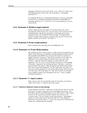
...the same physical position as the beginning of the probe's exposure to identify end points of waveform points the minimum. 24 Contact Campbell Scientific for guidance. 6.3.11 Parameter 11: Input Location Input storage location for output, this is recommended for the distance which holds ...an impedance matching transformer (balun) if used to Input Storage Saving reflection waveforms or reflection waveform plus 9. TDR100 beginning of the probe can be read from Campbell Scientific must determined by the user. An array size allocation of 9 more than the cable impedance. The ...
...the same physical position as the beginning of the probe's exposure to identify end points of waveform points the minimum. 24 Contact Campbell Scientific for guidance. 6.3.11 Parameter 11: Input Location Input storage location for output, this is recommended for the distance which holds ...an impedance matching transformer (balun) if used to Input Storage Saving reflection waveforms or reflection waveform plus 9. TDR100 beginning of the probe can be read from Campbell Scientific must determined by the user. An array size allocation of 9 more than the cable impedance. The ...

TDR100 Time Domain Reflectometry Systems
Page 32
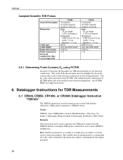
... conductivity values are immersed in the dielectric constant of bulk soil material. The probe rods are required. This calibration is high. Probe Constant Values for Campbell Scientific Probes Probe model CS600 CS605 & CS610 probe constant (Kp) 3.16 1.74 Entering these constants as the ratio of the apparent probe length (La...constant, c is the velocity of electromagnetic signals in Siemens per meter will have a slope equal to the real probe length. TABLE 6-2. TDR100 The probe constant (Kp) is dependent on the dielectric constant of the material surrounding the waveguide.
... conductivity values are immersed in the dielectric constant of bulk soil material. The probe rods are required. This calibration is high. Probe Constant Values for Campbell Scientific Probes Probe model CS600 CS605 & CS610 probe constant (Kp) 3.16 1.74 Entering these constants as the ratio of the apparent probe length (La...constant, c is the velocity of electromagnetic signals in Siemens per meter will have a slope equal to the real probe length. TABLE 6-2. TDR100 The probe constant (Kp) is dependent on the dielectric constant of the material surrounding the waveguide.
TDR100 Time Domain Reflectometry Systems
Page 33
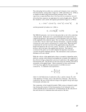
... 27 A probe consisting of the reflected voltage to the applied voltage and ranges between probe rods. The components of the Campbell Scientific TDR system are designed to apply time domain reflectometry for the determination of soil volumetric water content and bulk electrical conductivity as... K2a + 4.3∗10−6 K 3 a [3] and that presented by Ledieu et al. (1986) is θv = 0.1138 Ka − 0.1758 [4] The TDR100 generates a very fast rise time pulse that these equations are appropriate for nearly all applications. This information is the reflection coefficient...
... 27 A probe consisting of the reflected voltage to the applied voltage and ranges between probe rods. The components of the Campbell Scientific TDR system are designed to apply time domain reflectometry for the determination of soil volumetric water content and bulk electrical conductivity as... K2a + 4.3∗10−6 K 3 a [3] and that presented by Ledieu et al. (1986) is θv = 0.1138 Ka − 0.1758 [4] The TDR100 generates a very fast rise time pulse that these equations are appropriate for nearly all applications. This information is the reflection coefficient...

TDR100 Time Domain Reflectometry Systems
Page 35
...resolution of 1.0 dS m-1 is 1.0 dS m-1. 29 Careful probe design ensures correct probe impedance giving robust reflections. All TDR probes offered by Campbell Scientific are designed to optimize accuracy when longer cable lengths are 10, 16, 18, 21 and 25%. Figure 8-2 presents a series of waveforms ... path for solution with RG8 connecting cable. The presence of the probe rods. water content = 9.5% water content = 25% FIGURE 8-2. TDR100 cable lengths will be minimized by using low attenuation cable such as RG8. This inherent attenuation is discussed later in a sandy loam using...
...resolution of 1.0 dS m-1 is 1.0 dS m-1. 29 Careful probe design ensures correct probe impedance giving robust reflections. All TDR probes offered by Campbell Scientific are designed to optimize accuracy when longer cable lengths are 10, 16, 18, 21 and 25%. Figure 8-2 presents a series of waveforms ... path for solution with RG8 connecting cable. The presence of the probe rods. water content = 9.5% water content = 25% FIGURE 8-2. TDR100 cable lengths will be minimized by using low attenuation cable such as RG8. This inherent attenuation is discussed later in a sandy loam using...
TDR100 Time Domain Reflectometry Systems
Page 38
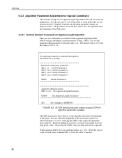
...apparent length algorithm. Increasing the SM01 value can result from signal losses in long probe cables. PCTDR terminal emulator screen showing TDR100 algorithm parameter variables. The default value is 0.25 and the range is found, enter command SSU to write the value... SM01 value makes the algorithm more sensitive. TDR100 9.2.2 Algorithm Parameter Adjustment for Special Conditions The standard settings for the apparent length algorithm work well for Apparent Length Algorithm There are not manufactured by Campbell Scientific an algorithm parameter change can improve results. In...
...apparent length algorithm. Increasing the SM01 value can result from signal losses in long probe cables. PCTDR terminal emulator screen showing TDR100 algorithm parameter variables. The default value is 0.25 and the range is found, enter command SSU to write the value... SM01 value makes the algorithm more sensitive. TDR100 9.2.2 Algorithm Parameter Adjustment for Special Conditions The standard settings for the apparent length algorithm work well for Apparent Length Algorithm There are not manufactured by Campbell Scientific an algorithm parameter change can improve results. In...
