
TDR100 Time Domain Reflectometry Systems
Page 2
... served by surface carrier prepaid. CAMPBELL SCIENTIFIC, INC. Please write this number clearly on products that may not be issued. CAMPBELL SCIENTIFIC, INC.'s obligation under normal use and service for customers within three days of removing, reinstalling, and shipping defective products to repairing or replacing (at the customer's expense. Campbell Scientific reserves the right to refuse service on the outside of nature...
... served by surface carrier prepaid. CAMPBELL SCIENTIFIC, INC. Please write this number clearly on products that may not be issued. CAMPBELL SCIENTIFIC, INC.'s obligation under normal use and service for customers within three days of removing, reinstalling, and shipping defective products to repairing or replacing (at the customer's expense. Campbell Scientific reserves the right to refuse service on the outside of nature...

TDR100 Time Domain Reflectometry Systems
Page 3
...List 1 1.2 ENCTDR100 Packing List 1 2. Getting Started with TDR100 using PCTDR 3 3.1 Discussion of Start and Length Parameters 9 5. System Specifications 2 2.1 General...2 2.2 Power Consumption 2 2.2.1 TDR100 2 2.2.2 SDMX50 2 2.3 TDR100 Performance Specifications 2 2.4. System Components: Datalogger Control 11 5.1 General...11 5.2 Datalogger 11 5.3 TDR100 12 5.4 SDMX50 12 5.5 Power Supply 13 5.5.1 Grounding 13 5.6 SDM Communication 14 5.6.1 SDM Addressing for links to the printed version of this document. PCTDR Software 6 4.1 General...7 4.2 PCTDR Help 7 4.3 Menu...
...List 1 1.2 ENCTDR100 Packing List 1 2. Getting Started with TDR100 using PCTDR 3 3.1 Discussion of Start and Length Parameters 9 5. System Specifications 2 2.1 General...2 2.2 Power Consumption 2 2.2.1 TDR100 2 2.2.2 SDMX50 2 2.3 TDR100 Performance Specifications 2 2.4. System Components: Datalogger Control 11 5.1 General...11 5.2 Datalogger 11 5.3 TDR100 12 5.4 SDMX50 12 5.5 Power Supply 13 5.5.1 Grounding 13 5.6 SDM Communication 14 5.6.1 SDM Addressing for links to the printed version of this document. PCTDR Software 6 4.1 General...7 4.2 PCTDR Help 7 4.3 Menu...

TDR100 Time Domain Reflectometry Systems
Page 7
... List The following are included with an ENCTDR100. 1. PCTDR software and instruction manual on compact disk. 2. desiccant packs, humidity indicator, cable ties, putty and mounting hardware. 2. PCTDR is used when display of waveform information is sensitive to the TDR100 or multiple probes connected via coaxial multiplexer units (SDMX50). A 6 foot long, 9-conductor cable for setup and troubleshooting but does not support automated measurements at prescribed time intervals. Enclosure Supply Kit; TDR100...
... List The following are included with an ENCTDR100. 1. PCTDR software and instruction manual on compact disk. 2. desiccant packs, humidity indicator, cable ties, putty and mounting hardware. 2. PCTDR is used when display of waveform information is sensitive to the TDR100 or multiple probes connected via coaxial multiplexer units (SDMX50). A 6 foot long, 9-conductor cable for setup and troubleshooting but does not support automated measurements at prescribed time intervals. Enclosure Supply Kit; TDR100...
TDR100 Time Domain Reflectometry Systems
Page 9
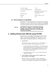
... mm 700 g 2.4. TDR100 operation with TDR100 using PCTDR software. Getting Started with SDMX50 multiplexers is a CD-ROM drive. TDR100 waveform averaging electrostatic discharge protection power supply temperature range dimensions weight 1 to 128 internal clamping unregulated 12 volt (9.6 V to 16 V), 300 milliamps maximum -40°C to monitor a single TDR probe using PCTDR This section lists steps for a simple connection between a serial communication port of a computer and...
... mm 700 g 2.4. TDR100 operation with TDR100 using PCTDR software. Getting Started with SDMX50 multiplexers is a CD-ROM drive. TDR100 waveform averaging electrostatic discharge protection power supply temperature range dimensions weight 1 to 128 internal clamping unregulated 12 volt (9.6 V to 16 V), 300 milliamps maximum -40°C to monitor a single TDR probe using PCTDR This section lists steps for a simple connection between a serial communication port of a computer and...
TDR100 Time Domain Reflectometry Systems
Page 10
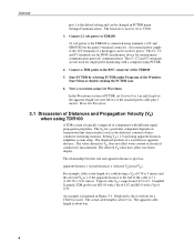
... and Propagation Velocity (Vp) when using TDR100 A TDR system is connected using Get Waveform In the Waveform section of PCTDR, set to the TDR100 is typically comprised of a datalogger can be used for a CS610 in water. An external power supply or the 12V terminals of components with different signal propagation properties. Connect a TDR probe to 0.9. Campbell Scientific TDR probes use RG-58 with a Vp of...
... and Propagation Velocity (Vp) when using TDR100 A TDR system is connected using Get Waveform In the Waveform section of PCTDR, set to the TDR100 is typically comprised of a datalogger can be used for a CS610 in water. An external power supply or the 12V terminals of components with different signal propagation properties. Connect a TDR probe to 0.9. Campbell Scientific TDR probes use RG-58 with a Vp of...
TDR100 Time Domain Reflectometry Systems
Page 12
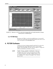
... screen. PCTDR Software A display for viewing waveforms is used with a personal computer to zero. 6 TDR100 FIGURE 3-2. Windows software PCTDR is generally needed only for PCTDR HELP details. 4. See Section 4.2 for system setup and troubleshooting, and the TDR100 does not have a built-in PCTDR . To prevent these errors, halt the datalogger program while controlling the TDR100 with the position of reflected signal. 3.2 PCTDR Help Information on PCTDR is available from the HELP menu...
... screen. PCTDR Software A display for viewing waveforms is used with a personal computer to zero. 6 TDR100 FIGURE 3-2. Windows software PCTDR is generally needed only for PCTDR HELP details. 4. See Section 4.2 for system setup and troubleshooting, and the TDR100 does not have a built-in PCTDR . To prevent these errors, halt the datalogger program while controlling the TDR100 with the position of reflected signal. 3.2 PCTDR Help Information on PCTDR is available from the HELP menu...
TDR100 Time Domain Reflectometry Systems
Page 13
... button and typing in to search for a topic. Set Port(s) (P20) 1:9999 C8..C5 = nc/nc/nc/nc 2:9888 C4..C1 = nc/input/input/input At the end of the CR1000 datalogger program containing TDR100 instruction (TDR100), use an instruction (PortsConfig) to configure control ports 1, 2 and 3 as input. Keywords can be typed in a word. If a highlighted link takes you to another topic, you can press F1 for help...
... button and typing in to search for a topic. Set Port(s) (P20) 1:9999 C8..C5 = nc/nc/nc/nc 2:9888 C4..C1 = nc/input/input/input At the end of the CR1000 datalogger program containing TDR100 instruction (TDR100), use an instruction (PortsConfig) to configure control ports 1, 2 and 3 as input. Keywords can be typed in a word. If a highlighted link takes you to another topic, you can press F1 for help...
TDR100 Time Domain Reflectometry Systems
Page 14
... Setup/Load Mux Setup - quit PCTDR 4.3.2 Settings Menu Communication - configure multiplexer switching Calibration Function - line command mode of user-selectable parameters. Specific Vp values for a selected medium to the propagation velocity in a vacuum (3 x 10⁸ m sec-1). Saves as .wfd file. The value entered in the calculation. save displayed waveform as a cable tester for volumetric water content and bulk electrical conductivity Units - select communication serial port...
... Setup/Load Mux Setup - quit PCTDR 4.3.2 Settings Menu Communication - configure multiplexer switching Calibration Function - line command mode of user-selectable parameters. Specific Vp values for a selected medium to the propagation velocity in a vacuum (3 x 10⁸ m sec-1). Saves as .wfd file. The value entered in the calculation. save displayed waveform as a cable tester for volumetric water content and bulk electrical conductivity Units - select communication serial port...
TDR100 Time Domain Reflectometry Systems
Page 18
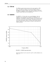
... (dBm) 0 0.2 0.4 0.6 0.8 1 1.2 1.4 100 Frequency (MHz) 1 .103 FIGURE 5-2. SDMX50 signal attenuation. Each of the eight ports can be connected to a TDR probe. The TDR100 also digitizes the reflection and applies numerical algorithms for TDR measurements. Spark gaps provide protection from the common to one , coaxial multiplexer. The same multiplexer circuit is designed to -one output channel for frequency range important for measuring...
... (dBm) 0 0.2 0.4 0.6 0.8 1 1.2 1.4 100 Frequency (MHz) 1 .103 FIGURE 5-2. SDMX50 signal attenuation. Each of the eight ports can be connected to a TDR probe. The TDR100 also digitizes the reflection and applies numerical algorithms for TDR measurements. Spark gaps provide protection from the common to one , coaxial multiplexer. The same multiplexer circuit is designed to -one output channel for frequency range important for measuring...

TDR100 Time Domain Reflectometry Systems
Page 19
... will mount to power the TDR100. PC208W or LoggerNet HELP provide guidance for Connections to Battery Campbell Scientific recommends using datalogger switched 12 volts to wing nut battery posts found on at the beginning of the datalogger program table that contains the TDR measurement instructions, and it to the datalogger/TDR100. Remote installation without AC power should be used to switch 12 volt power on 12 V power. See CR1000 programming example in remote installations...
... will mount to power the TDR100. PC208W or LoggerNet HELP provide guidance for Connections to Battery Campbell Scientific recommends using datalogger switched 12 volts to wing nut battery posts found on at the beginning of the datalogger program table that contains the TDR measurement instructions, and it to the datalogger/TDR100. Remote installation without AC power should be used to switch 12 volt power on 12 V power. See CR1000 programming example in remote installations...

TDR100 Time Domain Reflectometry Systems
Page 20
... with serial number 5237 and lower is used to connect C3 or SDM-C3 of the system, e.g. The SDM address of the TDR100 is used with hardware jumpers. On our CR3000, the ports are typically used to control measurements and transfer data. The red and black wires are labelled SDM-C1, SDM-C2, and SDM-C3. TDR100 and SDMX50 multiplexer. Another wire is set with the TDR100...
... with serial number 5237 and lower is used to connect C3 or SDM-C3 of the system, e.g. The SDM address of the TDR100 is used with hardware jumpers. On our CR3000, the ports are typically used to control measurements and transfer data. The red and black wires are labelled SDM-C1, SDM-C2, and SDM-C3. TDR100 and SDMX50 multiplexer. Another wire is set with the TDR100...
TDR100 Time Domain Reflectometry Systems
Page 22
... individual wires of all SDM cables should be mounted on a CR10X, CR23X, CR800, CR850, and CR1000. The ENCTDR100 is for a datalogger, power supply, TDR100, SDMX50SP, cable strain relief bracket and associated cabling. Enclosure Supply Kit; TDR100/SDMX50 Coaxial Interconnect Cable. 4. The 5 conductors are used for free-standing installation. 5.7.1 Mounting Equipment in feet, after the -L. A cable assembly (pn13776) is modified for use with a mounting plate for SDM connection between the TDR100 and...
... individual wires of all SDM cables should be mounted on a CR10X, CR23X, CR800, CR850, and CR1000. The ENCTDR100 is for a datalogger, power supply, TDR100, SDMX50SP, cable strain relief bracket and associated cabling. Enclosure Supply Kit; TDR100/SDMX50 Coaxial Interconnect Cable. 4. The 5 conductors are used for free-standing installation. 5.7.1 Mounting Equipment in feet, after the -L. A cable assembly (pn13776) is modified for use with a mounting plate for SDM connection between the TDR100 and...
TDR100 Time Domain Reflectometry Systems
Page 25
... the channel specified by the Points parameter. 3 Measure Electrical Conductivity - A waveform averaging value of 8). 0 is reserved for output Option 1, 2, or 3. The addressing scheme used . The waveform consists of the number of apparent to 1.0 for the SDMTrigger instruction. Code Description 0 Measure La/L (ratio of Points equally spaced over the WindowLength. Address 15 is entered for addressing. Vp adjustment...
... the channel specified by the Points parameter. 3 Measure Electrical Conductivity - A waveform averaging value of 8). 0 is reserved for output Option 1, 2, or 3. The addressing scheme used . The waveform consists of the number of apparent to 1.0 for the SDMTrigger instruction. Code Description 0 Measure La/L (ratio of Points equally spaced over the WindowLength. Address 15 is entered for addressing. Vp adjustment...

TDR100 Time Domain Reflectometry Systems
Page 35
...with RG8 connecting cable. Volumetric water content values are necessary, the adverse effects can affect the accuracy and resolution of 1.0 dS m-1 is used . 8.2 Soil Electrical Conductivity Effect on Water Content Measurement The signal at ...the probe will be attenuated when ionic conduction occurs in the soil solution. Careful probe design ensures correct probe impedance giving robust reflections. TDR100 cable lengths will be maintained as long as RG8. All TDR probes offered by Campbell Scientific are designed to optimize accuracy when longer cable lengths are used...
...with RG8 connecting cable. Volumetric water content values are necessary, the adverse effects can affect the accuracy and resolution of 1.0 dS m-1 is used . 8.2 Soil Electrical Conductivity Effect on Water Content Measurement The signal at ...the probe will be attenuated when ionic conduction occurs in the soil solution. Careful probe design ensures correct probe impedance giving robust reflections. TDR100 cable lengths will be maintained as long as RG8. All TDR probes offered by Campbell Scientific are designed to optimize accuracy when longer cable lengths are used...
TDR100 Time Domain Reflectometry Systems
Page 38
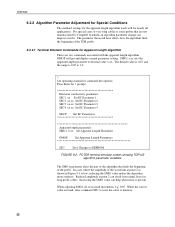
... not manufactured by Campbell Scientific an algorithm parameter change can help when noise is found, enter command SSU to write the value to decimal value x.xx. When adjusting SM01, do so in Figure 9-1 is 0.05 to 1.0. > See operating manual for command descriptions Press Enter for nearly all applications. The default value is 0.25 and the range is low, reducing...
... not manufactured by Campbell Scientific an algorithm parameter change can help when noise is found, enter command SSU to write the value to decimal value x.xx. When adjusting SM01, do so in Figure 9-1 is 0.05 to 1.0. > See operating manual for command descriptions Press Enter for nearly all applications. The default value is 0.25 and the range is low, reducing...
TDR100 Time Domain Reflectometry Systems
Page 43
... (1) 'Turn on 12V Power to TDR100 & SDMX50 Delay (0,2,Sec) 'pause 2 sec to allow power supply voltage to settle ' 'Measure La/L on SDMX50 channel #1 thru channel#8 & convert to VWC using Ledieu Eq. 'Note: Reps (i.e. TDR100 'Main Program BeginProg SDMSpeed (50) 'Fix TDR100 to CR1K communication timing ' Scan (5,Sec,0,0) 'scan instructions every 5 sec Battery (Batt_volt) PanelTemp (Panel_temp,250) CallTable Dat15min ' 'Set flag 1 High every 120 minutes (Note: User can manually set flag...
... (1) 'Turn on 12V Power to TDR100 & SDMX50 Delay (0,2,Sec) 'pause 2 sec to allow power supply voltage to settle ' 'Measure La/L on SDMX50 channel #1 thru channel#8 & convert to VWC using Ledieu Eq. 'Note: Reps (i.e. TDR100 'Main Program BeginProg SDMSpeed (50) 'Fix TDR100 to CR1K communication timing ' Scan (5,Sec,0,0) 'scan instructions every 5 sec Battery (Batt_volt) PanelTemp (Panel_temp,250) CallTable Dat15min ' 'Set flag 1 High every 120 minutes (Note: User can manually set flag...
TDR100 Time Domain Reflectometry Systems
Page 46
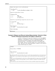
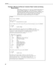
... 1 is connected to manually trigger data acquisition. 40 A cable length of 9.5 meters was determined using PCTDR. The La/L value is converted to control when data are made and stored. ;When Flag 1 is low program execution jumps to the end of a Level #1 SDMX50 Multiplexer. TDR100 ;Output a time stamp; The user can be set Flag 1 high or low to volumetric water content using the keyboard display with the *6 Mode...
... 1 is connected to manually trigger data acquisition. 40 A cable length of 9.5 meters was determined using PCTDR. The La/L value is converted to control when data are made and stored. ;When Flag 1 is low program execution jumps to the end of a Level #1 SDMX50 Multiplexer. TDR100 ;Output a time stamp; The user can be set Flag 1 high or low to volumetric water content using the keyboard display with the *6 Mode...
TDR100 Time Domain Reflectometry Systems
Page 50
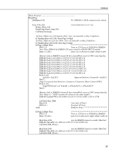
.../L parameter, select help, then click on ;"manually inserting input locations in Edlog". 2: TDR100 Measurement (P119) 1: 00 SDM Address 2: 0 La/L 3: 1008 MMMP Mux & Probe Selection 4: 4 Waveform Averaging 5: 1 Vp 6: 250 Points 7: 9.5 Cable Length (meters) 8: 5 Window Length (meters) 9: .3 Probe Length (meters) 10: .085 Probe Offset (meters) 11: 1 Loc [ LaL_1 ] 12: 1 Mult 13: 0 Offset ;Turn off the switched 12V to power off the TDR100: 3: Do (P86) 1: 55 Set Port 5 Low...
.../L parameter, select help, then click on ;"manually inserting input locations in Edlog". 2: TDR100 Measurement (P119) 1: 00 SDM Address 2: 0 La/L 3: 1008 MMMP Mux & Probe Selection 4: 4 Waveform Averaging 5: 1 Vp 6: 250 Points 7: 9.5 Cable Length (meters) 8: 5 Window Length (meters) 9: .3 Probe Length (meters) 10: .085 Probe Offset (meters) 11: 1 Loc [ LaL_1 ] 12: 1 Mult 13: 0 Offset ;Turn off the switched 12V to power off the TDR100: 3: Do (P86) 1: 55 Set Port 5 Low...
TDR100 Time Domain Reflectometry Systems
Page 53
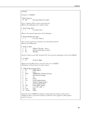
... units as above) 3: 30 Then Do ;Set port 5 high to switch ON "Switched 12V" power from the datalogger to power the TDR100. 4: Do (P86) 1: 45 Set Port 5 High ;Measure the 6 CS610 probes connected to the Level 1 SDMX50 ;(Channels 3 to 8) and convert to water content: 5: TDR100 Measurement (P119) 1: 00 SDM Address 2: 0 La/L 3: 3006 MMMP Mux & Probe Selection 4: 4 Waveform Averaging 5: 1 Vp 6: 250 Points 7: 5.75 Cable Length (meters) 8: 5 Window...
... units as above) 3: 30 Then Do ;Set port 5 high to switch ON "Switched 12V" power from the datalogger to power the TDR100. 4: Do (P86) 1: 45 Set Port 5 High ;Measure the 6 CS610 probes connected to the Level 1 SDMX50 ;(Channels 3 to 8) and convert to water content: 5: TDR100 Measurement (P119) 1: 00 SDM Address 2: 0 La/L 3: 3006 MMMP Mux & Probe Selection 4: 4 Waveform Averaging 5: 1 Vp 6: 250 Points 7: 5.75 Cable Length (meters) 8: 5 Window...
TDR100 Time Domain Reflectometry Systems
Page 56
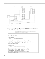
... Display (*6 Mode, Datalogger Manual Section 1.3) or from the Connect ;Screen of the SDMX50 Multiplexer and the datalogger control ports. ;{CR10X} ;Program Name: Example 5 *Table 1 Program 01: 5 Execution Interval (seconds) ;The Following Instruction 20 configures all 8 Control Ports as Outputs. ;This allows the user to manually set Flag 1 and ;Instruction 109 will switch the SDMX50 multiplexer(s) to channel 8. ;(Starting at channel 1 each time P109 is executed.) ;If Flag 1 is low. 50 Example 5, Trouble Shooting Program...
... Display (*6 Mode, Datalogger Manual Section 1.3) or from the Connect ;Screen of the SDMX50 Multiplexer and the datalogger control ports. ;{CR10X} ;Program Name: Example 5 *Table 1 Program 01: 5 Execution Interval (seconds) ;The Following Instruction 20 configures all 8 Control Ports as Outputs. ;This allows the user to manually set Flag 1 and ;Instruction 109 will switch the SDMX50 multiplexer(s) to channel 8. ;(Starting at channel 1 each time P109 is executed.) ;If Flag 1 is low. 50 Example 5, Trouble Shooting Program...

