
TDR100 Time Domain Reflectometry Systems
Page 7
...Campbell Scientific. The TDR100 and SDMX50 multiplexers can be configured for automatic control using TDR100 instruction with a CR800, CR850, CR1000, or CR3000 datalogger or Instruction 119 with a CR10X or CR23X datalogger. PCTDR software and instruction manual on compact disk. 2. Enclosure Supply Kit; TDR100/SDMX50 and TDR100...5-conductor cables for detailed information about TDR probes available from our website: www.campbellsci.com/manuals. TDR100 1. TDR100/SDMX50 Coaxial Interconnect Cable. 4. Introduction This document presents operating instructions for external deep cycle ...
...Campbell Scientific. The TDR100 and SDMX50 multiplexers can be configured for automatic control using TDR100 instruction with a CR800, CR850, CR1000, or CR3000 datalogger or Instruction 119 with a CR10X or CR23X datalogger. PCTDR software and instruction manual on compact disk. 2. Enclosure Supply Kit; TDR100/SDMX50 and TDR100...5-conductor cables for detailed information about TDR probes available from our website: www.campbellsci.com/manuals. TDR100 1. TDR100/SDMX50 Coaxial Interconnect Cable. 4. Introduction This document presents operating instructions for external deep cycle ...

TDR100 Time Domain Reflectometry Systems
Page 8
...General See the CR10X, CR23X, CR800/CR850, CR1000, or CR3000 datalogger manuals for datalogger specifications. 2.2 Power Consumption 2.2.1 TDR100 • The current demand for the SDMX50 multiplexer is less than 1 second. 2.3 TDR100 Performance Specifications pulse generator output output impedance time response of the same level ...switch simultaneously (see Figure 5-1). After 35 seconds in sleep mode, a timer puts the TDR100 in standby mode requiring about 2 milliamps. • When the TDR100 is controlled by a datalogger, a 35 second timer puts the device in low power mode ...
...General See the CR10X, CR23X, CR800/CR850, CR1000, or CR3000 datalogger manuals for datalogger specifications. 2.2 Power Consumption 2.2.1 TDR100 • The current demand for the SDMX50 multiplexer is less than 1 second. 2.3 TDR100 Performance Specifications pulse generator output output impedance time response of the same level ...switch simultaneously (see Figure 5-1). After 35 seconds in sleep mode, a timer puts the TDR100 in standby mode requiring about 2 milliamps. • When the TDR100 is controlled by a datalogger, a 35 second timer puts the device in low power mode ...

TDR100 Time Domain Reflectometry Systems
Page 19
..., CR1000, or CR3000 datalogger. This will provide power savings and will mount to set a control port for discussion of this manual. This practice can be used in the program example section of the enclosure. A good earth ground should keep the battery charged... program table that contains the TDR measurement instructions, and it to the datalogger/TDR100. Two terminal strip adapters for connection to power the TDR100. PC208W or LoggerNet HELP provide guidance for Connections to Battery Campbell Scientific recommends using datalogger switched 12 volts to the 13
..., CR1000, or CR3000 datalogger. This will provide power savings and will mount to set a control port for discussion of this manual. This practice can be used in the program example section of the enclosure. A good earth ground should keep the battery charged... program table that contains the TDR measurement instructions, and it to the datalogger/TDR100. Two terminal strip adapters for connection to power the TDR100. PC208W or LoggerNet HELP provide guidance for Connections to Battery Campbell Scientific recommends using datalogger switched 12 volts to the 13

TDR100 Time Domain Reflectometry Systems
Page 28
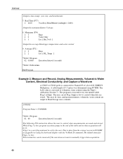
... electrical conductivity routine in the datalogger returns the value 1 1− ρ Zc 1+ ρ which must be collected from the TDR100 by the probe constant, Kp, to datalogger input storage. Level 3 multiplexer channel n -- Note: enter a 0 when a level is... channel C -- Datalogger input storage must be manually allocated for the level 1 multiplexer. 0 the level 2 multiplexer is not used . 22 Input storage must be manually allocated. See Section 6.2.11.1 for the highest level multiplexer. TDR100 6.3.2.2 Enter 1: Collect Waveform The digitized reflection waveform...
... electrical conductivity routine in the datalogger returns the value 1 1− ρ Zc 1+ ρ which must be collected from the TDR100 by the probe constant, Kp, to datalogger input storage. Level 3 multiplexer channel n -- Note: enter a 0 when a level is... channel C -- Datalogger input storage must be manually allocated for the level 1 multiplexer. 0 the level 2 multiplexer is not used . 22 Input storage must be manually allocated. See Section 6.2.11.1 for the highest level multiplexer. TDR100 6.3.2.2 Enter 1: Collect Waveform The digitized reflection waveform...
TDR100 Time Domain Reflectometry Systems
Page 30
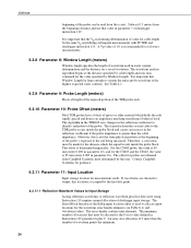
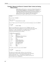
...manual allocation of datalogger input storage. If waveforms are chosen for a saved waveform. An array size allocation of 9 more than the cable impedance. The waveform analysis algorithm begins at the highest expected water contents. The algorithm in the TDR100 uses changes in parameter 10). The transition from Campbell Scientific... elements (see Table 6-1) and waveform values. Therefore, a correction must determined by the user. Contact Campbell Scientific for guidance. 6.3.11 Parameter 11: Input Location Input storage location for the value specified by Window Length...
...manual allocation of datalogger input storage. If waveforms are chosen for a saved waveform. An array size allocation of 9 more than the cable impedance. The waveform analysis algorithm begins at the highest expected water contents. The algorithm in the TDR100 uses changes in parameter 10). The transition from Campbell Scientific... elements (see Table 6-1) and waveform values. Therefore, a correction must determined by the user. Contact Campbell Scientific for guidance. 6.3.11 Parameter 11: Input Location Input storage location for the value specified by Window Length...
TDR100 Time Domain Reflectometry Systems
Page 38
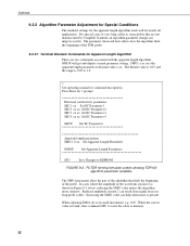
.... 9.2.2.1 Terminal Emulator Commands for Apparent Length Algorithm There are not manufactured by Campbell Scientific an algorithm parameter change can help when noise is 0.05 to 1.0. > See operating manual for command descriptions Press Enter for nearly all applications. The parameter discussed here ...setting. The SMO1 parameter alters the part of the algorithm that are two commands associated with the apparent length algorithm. TDR100 9.2.2 Algorithm Parameter Adjustment for Special Conditions The standard settings for the apparent length algorithm work well for > prompt Electrical...
.... 9.2.2.1 Terminal Emulator Commands for Apparent Length Algorithm There are not manufactured by Campbell Scientific an algorithm parameter change can help when noise is 0.05 to 1.0. > See operating manual for command descriptions Press Enter for nearly all applications. The parameter discussed here ...setting. The SMO1 parameter alters the part of the algorithm that are two commands associated with the apparent length algorithm. TDR100 9.2.2 Algorithm Parameter Adjustment for Special Conditions The standard settings for the apparent length algorithm work well for > prompt Electrical...
TDR100 Time Domain Reflectometry Systems
Page 43
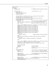
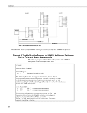
... Program BeginProg SDMSpeed (50) 'Fix TDR100 to CR1K communication timing ' Scan (5,Sec,0,0) 'scan instructions every 5 sec Battery (Batt_volt) PanelTemp (Panel_temp,250) CallTable Dat15min ' 'Set flag 1 High every 120 minutes (Note: User can manually set flag 1 high/low) If TimeIntoInterval(0,2,Hr) Then Flag... flag 2 High once per day (Note: User can manually set flag 2 high/low) If TimeIntoInterval(0,24,Hr) then flag(2)=high ' If Flag(1)=High Then SW12 (1) 'Turn on 12V Power to TDR100 & SDMX50 'Note: Wire TDR100 & SDMX50 12V power leads to CR1000 SW12 Terminal Delay ...
... Program BeginProg SDMSpeed (50) 'Fix TDR100 to CR1K communication timing ' Scan (5,Sec,0,0) 'scan instructions every 5 sec Battery (Batt_volt) PanelTemp (Panel_temp,250) CallTable Dat15min ' 'Set flag 1 High every 120 minutes (Note: User can manually set flag 1 high/low) If TimeIntoInterval(0,2,Hr) Then Flag... flag 2 High once per day (Note: User can manually set flag 2 high/low) If TimeIntoInterval(0,24,Hr) then flag(2)=high ' If Flag(1)=High Then SW12 (1) 'Turn on 12V Power to TDR100 & SDMX50 'Note: Wire TDR100 & SDMX50 12V power leads to CR1000 SW12 Terminal Delay ...
TDR100 Time Domain Reflectometry Systems
Page 46
TDR100 ;Output a time stamp; This is low. ;This instruction can set by the user. The default status for Flags 1 is done from the connect screen in PC208W or LoggerNet or using the Topp's calibration (Section 7). The program is executed every one minute while Flag 1 is connected to manually trigger data acquisition. 40 The...
TDR100 ;Output a time stamp; This is low. ;This instruction can set by the user. The default status for Flags 1 is done from the connect screen in PC208W or LoggerNet or using the Topp's calibration (Section 7). The program is executed every one minute while Flag 1 is connected to manually trigger data acquisition. 40 The...
TDR100 Time Domain Reflectometry Systems
Page 50
... CS610 probes connected to the level 1 SDMX50, return La/L: ;When creating the program with each ;pass through the loop. (Index an input location in Edlog". 2: TDR100 Measurement (P119) 1: 00 SDM Address 2: 0 La/L 3: 1008 MMMP Mux & Probe Selection 4: 4 Waveform Averaging 5: 1 Vp 6: 250 Points 7: 9.5 Cable ...right mouse click the La/L parameter, select help, then click on ;"manually inserting input locations in Edlog by pressing "F4" ;while the input location is converted with Edlog, the user must manually allocate the 8 input ;locations (i.e.: "LaL_1" through LaL_8"). For ...
... CS610 probes connected to the level 1 SDMX50, return La/L: ;When creating the program with each ;pass through the loop. (Index an input location in Edlog". 2: TDR100 Measurement (P119) 1: 00 SDM Address 2: 0 La/L 3: 1008 MMMP Mux & Probe Selection 4: 4 Waveform Averaging 5: 1 Vp 6: 250 Points 7: 9.5 Cable ...right mouse click the La/L parameter, select help, then click on ;"manually inserting input locations in Edlog by pressing "F4" ;while the input location is converted with Edlog, the user must manually allocate the 8 input ;locations (i.e.: "LaL_1" through LaL_8"). For ...

TDR100 Time Domain Reflectometry Systems
Page 51
... = 2400) ;Output the 8 water content measurements and battery voltage: 12: Sample (P70) 1: 9 Reps 2: 11 Loc [ WC_1 ] TDR100 45 4: Beginning of the Loop. ;Measure the datalogger power supply voltage: 9: Batt Voltage (P10) 1: 19 Loc [ Bat_Volt ] ;Set...-0.055 C2 7: 0.0043 C3 8: 0.0 C4 9: 0.0 C5 8: End (P95) ; Z Loc [ WC_1 ] ;Multiply the dielectric constant by 0.1 to dielectric constant: ;Note: The user must manually allocate 8 input locations "WC_1" through WC_8". 5: Z=X*Y (P36) 1: 1 -- Y Loc [ LaL_1 ] 3: 11 -- X Loc [ WC_1 ] 3: 11 -- End of Loop (P87) ...
... = 2400) ;Output the 8 water content measurements and battery voltage: 12: Sample (P70) 1: 9 Reps 2: 11 Loc [ WC_1 ] TDR100 45 4: Beginning of the Loop. ;Measure the datalogger power supply voltage: 9: Batt Voltage (P10) 1: 19 Loc [ Bat_Volt ] ;Set...-0.055 C2 7: 0.0043 C3 8: 0.0 C4 9: 0.0 C5 8: End (P95) ; Z Loc [ WC_1 ] ;Multiply the dielectric constant by 0.1 to dielectric constant: ;Note: The user must manually allocate 8 input locations "WC_1" through WC_8". 5: Z=X*Y (P36) 1: 1 -- Y Loc [ LaL_1 ] 3: 11 -- X Loc [ WC_1 ] 3: 11 -- End of Loop (P87) ...
TDR100 Time Domain Reflectometry Systems
Page 56
Ports and flags can set the ports high (+5V) or low (0V) in order ;to manually set Flag 1 and ;Instruction 109 will NOT be set with ;the Keyboard Display (*6 Mode, Datalogger Manual Section 1.3) or from the Connect ;Screen of the SDMX50 Multiplexer and the datalogger control ports. ;{CR10X}... = output/output/output/output 2: 7777 C4..C1 = output/output/output/output ;To test wiring and multiplexer operation, the user can be executed. TDR100 FIGURE 10-1. Twenty-nine CS605 or CS610 probes connected to channel 8. ;(Starting at channel 1 each time P109 is executed.) ;If Flag 1 is...
Ports and flags can set the ports high (+5V) or low (0V) in order ;to manually set Flag 1 and ;Instruction 109 will NOT be set with ;the Keyboard Display (*6 Mode, Datalogger Manual Section 1.3) or from the Connect ;Screen of the SDMX50 Multiplexer and the datalogger control ports. ;{CR10X}... = output/output/output/output 2: 7777 C4..C1 = output/output/output/output ;To test wiring and multiplexer operation, the user can be executed. TDR100 FIGURE 10-1. Twenty-nine CS605 or CS610 probes connected to channel 8. ;(Starting at channel 1 each time P109 is executed.) ;If Flag 1 is...