
Hardware Installation Guide
Page 6
... PC 2-17 Connecting the Power Supply 2-18 Mounting Your Router 2-18 Mounting on a Table 2-18 Mounting on a Wall 2-19 Verifying Installation 2-20 Where to Go from Here 2-22 Troubleshooting 3-1 Problems During First Startup 3-2 Problems After First Startup 3-3 Problems After Router Is Running 3-5 When Contacting Your Cisco Reseller 3-7 ISDN and IDSL Concepts A-1 Specifications and Cables B-1 System Specifications B-1 Port Connector Pinouts B-2 Cabling Specifications B-6 Ethernet Cable Specifications B-7 Maximum Cable Distances B-7 Cisco 800 Series Routers Hardware Installation Guide vi 78-5373...
... PC 2-17 Connecting the Power Supply 2-18 Mounting Your Router 2-18 Mounting on a Table 2-18 Mounting on a Wall 2-19 Verifying Installation 2-20 Where to Go from Here 2-22 Troubleshooting 3-1 Problems During First Startup 3-2 Problems After First Startup 3-3 Problems After Router Is Running 3-5 When Contacting Your Cisco Reseller 3-7 ISDN and IDSL Concepts A-1 Specifications and Cables B-1 System Specifications B-1 Port Connector Pinouts B-2 Cabling Specifications B-6 Ethernet Cable Specifications B-7 Maximum Cable Distances B-7 Cisco 800 Series Routers Hardware Installation Guide vi 78-5373...

Hardware Installation Guide
Page 7
... the router is implemented on the router. • Specifications and Cables-Provides router, port, and cable specifications. • Glossary-Defines technical terms frequently used in this guide, and how to additional information and material. 78-5373-04 Cisco 800 Series Routers Hardware Installation Guide vii Organization This guide contains the following information: • About This Guide-Describes audience, organization, conventions used in this guide. Audience This guide is intended for installation as...
... the router is implemented on the router. • Specifications and Cables-Provides router, port, and cable specifications. • Glossary-Defines technical terms frequently used in this guide, and how to additional information and material. 78-5373-04 Cisco 800 Series Routers Hardware Installation Guide vii Organization This guide contains the following information: • About This Guide-Describes audience, organization, conventions used in this guide. Audience This guide is intended for installation as...

Hardware Installation Guide
Page 10
... documentation to correct all vulnerabilities quickly. A current list of your document or by calling 1 800 553-NETS (6387). psirt@cisco.com Cisco 800 Series Routers Hardware Installation Guide x 78-5373-04 Cisco Product Security Overview Cisco provides a free online Security Vulnerability Policy portal at this URL: http://www.cisco.com/en/US/products/products_security_vulnerability_policy.html From this URL: http://www.cisco.com/en/US/products/products_psirt_rss_feed.html Reporting Security Problems in Cisco Products Cisco...
... documentation to correct all vulnerabilities quickly. A current list of your document or by calling 1 800 553-NETS (6387). psirt@cisco.com Cisco 800 Series Routers Hardware Installation Guide x 78-5373-04 Cisco Product Security Overview Cisco provides a free online Security Vulnerability Policy portal at this URL: http://www.cisco.com/en/US/products/products_security_vulnerability_policy.html From this URL: http://www.cisco.com/en/US/products/products_psirt_rss_feed.html Reporting Security Problems in Cisco Products Cisco...

Hardware Installation Guide
Page 11
... In an emergency, you do not hold valid Cisco service contracts, Cisco Technical Support provides 24-hour-a-day, award-winning technical assistance. PSIRT can register at this URL: http://www.cisco.com/techsupport Access to all customers, partners, resellers, and distributors who hold a valid Cisco service contract, contact your product serial number before placing a service call. 78-5373-04 Cisco 800 Series Routers Hardware Installation Guide xi
... In an emergency, you do not hold valid Cisco service contracts, Cisco Technical Support provides 24-hour-a-day, award-winning technical assistance. PSIRT can register at this URL: http://www.cisco.com/techsupport Access to all customers, partners, resellers, and distributors who hold a valid Cisco service contract, contact your product serial number before placing a service call. 78-5373-04 Cisco 800 Series Routers Hardware Installation Guide xi
Hardware Installation Guide
Page 16
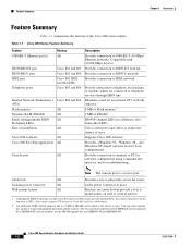
... Series Routers Hardware Installation Guide 1-2 78-5373-04 Feature Summary Chapter 1 Overview Feature Summary Table 1-1 summarizes the features of error. Eliminates need for basic configurations. The Cisco product number for the 8-MB Flash memory upgrade kit is a service port. Color-coded ports and cables to telephone, fax machine, or modem, which are MEM800-4D and MEM800-8D. Note The console port is MEM800-8F and the numbers for troubleshooting. You cannot connect S/T devices to physically secure...
... Series Routers Hardware Installation Guide 1-2 78-5373-04 Feature Summary Chapter 1 Overview Feature Summary Table 1-1 summarizes the features of error. Eliminates need for basic configurations. The Cisco product number for the 8-MB Flash memory upgrade kit is a service port. Color-coded ports and cables to telephone, fax machine, or modem, which are MEM800-4D and MEM800-8D. Note The console port is MEM800-8F and the numbers for troubleshooting. You cannot connect S/T devices to physically secure...
Hardware Installation Guide
Page 18
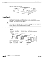
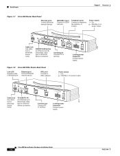
... CONSOLE ISDN S/T Cable lock Use cable lock to external NT1 or ISDN wall jack. Figure 1-4 Cisco 801 Router Back Panel Link LED Indicates state of Ethernet port. Cisco 800 Series Routers Hardware Installation Guide 1-4 78-5373-04 Warning If the symbol of suitability with an overlaid cross ( ) appears above a port, you must not connect the port to a public network that follows the European Union standards. Locking power connector Connect power supply. device connection. ISDN BRI S/T port Connect to physically secure router...
... CONSOLE ISDN S/T Cable lock Use cable lock to external NT1 or ISDN wall jack. Figure 1-4 Cisco 801 Router Back Panel Link LED Indicates state of Ethernet port. Cisco 800 Series Routers Hardware Installation Guide 1-4 78-5373-04 Warning If the symbol of suitability with an overlaid cross ( ) appears above a port, you must not connect the port to a public network that follows the European Union standards. Locking power connector Connect power supply. device connection. ISDN BRI S/T port Connect to physically secure router...
Hardware Installation Guide
Page 19
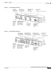
... T CONSOLE Cisco 802 ISDN U Cable lock Use cable lock to physically secure router. Locking power connector Connect power supply. 11667 Figure 1-6 Cisco 803 Router Back Panel Ethernet ports Connect Ethernet network devices. Console port Connect PC or terminal. PHONE 1 2 Locking power connector Connect power supply. 78-5373-04 Cisco 800 Series Routers Hardware Installation Guide 1-5 ISDN BRI S/T port Connect to external NT1 or ISDN wall jack. Chapter 1 Overview Back Panels Figure 1-5 Cisco 802 Router Back Panel Link LED Indicates state of Ethernet port. Power...
... T CONSOLE Cisco 802 ISDN U Cable lock Use cable lock to physically secure router. Locking power connector Connect power supply. 11667 Figure 1-6 Cisco 803 Router Back Panel Ethernet ports Connect Ethernet network devices. Console port Connect PC or terminal. PHONE 1 2 Locking power connector Connect power supply. 78-5373-04 Cisco 800 Series Routers Hardware Installation Guide 1-5 ISDN BRI S/T port Connect to external NT1 or ISDN wall jack. Chapter 1 Overview Back Panels Figure 1-5 Cisco 802 Router Back Panel Link LED Indicates state of Ethernet port. Power...
Hardware Installation Guide
Page 20
...PHONE 1 2 Locking power connector Connect power supply. Power switch l = On. = Standby or no power output. LINK TO TO HUB PC ETHERNET 10 BASE T CONSOLE Cisco 802 IDSL IDSL Cable lock Use cable lock to ISDN wall jack. TO HUB/TO PC (for Ethernet port) Determines cable type for Ethernet device connection. Back Panels Chapter 1 Overview Figure 1-7 Cisco 804 Router Back Panel Ethernet ports Connect Ethernet network devices. ISDN BRI U port Connect to physically secure router. Locking power connector Connect power supply. 30771 Cisco 800 Series Routers Hardware Installation Guide...
...PHONE 1 2 Locking power connector Connect power supply. Power switch l = On. = Standby or no power output. LINK TO TO HUB PC ETHERNET 10 BASE T CONSOLE Cisco 802 IDSL IDSL Cable lock Use cable lock to ISDN wall jack. TO HUB/TO PC (for Ethernet port) Determines cable type for Ethernet device connection. Back Panels Chapter 1 Overview Figure 1-7 Cisco 804 Router Back Panel Ethernet ports Connect Ethernet network devices. ISDN BRI U port Connect to physically secure router. Locking power connector Connect power supply. 30771 Cisco 800 Series Routers Hardware Installation Guide...
Hardware Installation Guide
Page 21
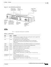
... a problem. Cisco 804 IDSL CONSOLE IDSL Console port Connect PC or terminal. Blinks when the internal NT1 and the ISDN switch are sent to physically secure router. Cisco 803 and 804 routers only. Off when the Ethernet device is not connected. Off when the Ethernet device is not connected. LEDs Table 1-3 summarizes the function of each LED. On when the Ethernet device is connected. Cisco 804 IDSL routers only. See the "Troubleshooting" chapter. 78-5373-04 Cisco 800 Series Routers Hardware Installation Guide 1-7 Blinks...
... a problem. Cisco 804 IDSL CONSOLE IDSL Console port Connect PC or terminal. Blinks when the internal NT1 and the ISDN switch are sent to physically secure router. Cisco 803 and 804 routers only. Off when the Ethernet device is not connected. Off when the Ethernet device is not connected. LEDs Table 1-3 summarizes the function of each LED. On when the Ethernet device is connected. Cisco 804 IDSL routers only. See the "Troubleshooting" chapter. 78-5373-04 Cisco 800 Series Routers Hardware Installation Guide 1-7 Blinks...

Hardware Installation Guide
Page 22
... the line speed is connected. Cisco 800 Series Routers Hardware Installation Guide 1-8 78-5373-04 LEDs Chapter 1 Overview Table 1-3 LED Functions (continued) LED CH1 CH1 RXD CH1 TXD CH2 CH2 RXD CH2 TXD PH1,PH2 LINK Color Orange Orange Orange Orange Orange Orange Green Green Function Blinks when placing or receiving a call on the second ISDN B channel. On back panel of Cisco 801, 802, and 802 IDSL routers only. On when Ethernet device...
... the line speed is connected. Cisco 800 Series Routers Hardware Installation Guide 1-8 78-5373-04 LEDs Chapter 1 Overview Table 1-3 LED Functions (continued) LED CH1 CH1 RXD CH1 TXD CH2 CH2 RXD CH2 TXD PH1,PH2 LINK Color Orange Orange Orange Orange Orange Orange Green Green Function Blinks when placing or receiving a call on the second ISDN B channel. On back panel of Cisco 801, 802, and 802 IDSL routers only. On when Ethernet device...

Hardware Installation Guide
Page 23
Installation CH A P T E R 2 This chapter provides information on the following topics: • Safety • European Union Statements • Preventing Electrostatic Discharge Damage • Preventing Router Damage • Unpacking Your Router • Preinstallation Activities • Installing Your Router • Mounting Your Router • Verifying Installation • Where to Go from Here 78-5373-04 Cisco 800 Series Routers Hardware Installation Guide 2-1
Installation CH A P T E R 2 This chapter provides information on the following topics: • Safety • European Union Statements • Preventing Electrostatic Discharge Damage • Preventing Router Damage • Unpacking Your Router • Preinstallation Activities • Installing Your Router • Mounting Your Router • Verifying Installation • Where to Go from Here 78-5373-04 Cisco 800 Series Routers Hardware Installation Guide 2-1

Hardware Installation Guide
Page 24
... LAN and WAN ports both use RJ-45 connectors. Cisco 800 Series Routers Hardware Installation Guide 2-2 78-5373-04 Warning Read the installation instructions before you must be handled according to all national laws and regulations. Any hardwired connection (other than by a nonremovable, connect-one-time-only plug) must not connect the port to a public network that has a standby/off switch, turn the power to standby and unplug the power cord. LAN ports contain...
... LAN and WAN ports both use RJ-45 connectors. Cisco 800 Series Routers Hardware Installation Guide 2-2 78-5373-04 Warning Read the installation instructions before you must be handled according to all national laws and regulations. Any hardwired connection (other than by a nonremovable, connect-one-time-only plug) must not connect the port to a public network that has a standby/off switch, turn the power to standby and unplug the power cord. LAN ports contain...
Hardware Installation Guide
Page 26
... color-coded ports on the back panel. • If you begin installing your Cisco 800 series router, perform the following : Cisco 800 Series Routers Hardware Installation Guide 2-4 78-5373-04 Table 2-1 Router Box Contents • Power cord (black) • Desktop power supply • Console cable (light blue) • DB-9-to-RJ-45 adapter for use with red ISDN U cable • Product documentation Preinstallation Activities Before you must not connect the port to the Cisco 800 Series Routers Software Configuration Guide. For more information, refer...
... color-coded ports on the back panel. • If you begin installing your Cisco 800 series router, perform the following : Cisco 800 Series Routers Hardware Installation Guide 2-4 78-5373-04 Table 2-1 Router Box Contents • Power cord (black) • Desktop power supply • Console cable (light blue) • DB-9-to-RJ-45 adapter for use with red ISDN U cable • Product documentation Preinstallation Activities Before you must not connect the port to the Cisco 800 Series Routers Software Configuration Guide. For more information, refer...
Hardware Installation Guide
Page 27
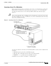
... jack. Connect the ISDN or IDSL line to the router. 2. Gather the Ethernet devices to be connected to the router: hub, server, workstation, or PC with 8-mm drill bit) to secure the screws. or 10/100-Mbps network interface card (NIC). with 5/16-in Appendix B, "Specifications and Cables." Installing Your Router To install the Cisco 800 series routers, you need to provide a Kensington or equivalent locking cable. Chapter 2 Installation Installing Your Router Step 3 Step...
... jack. Connect the ISDN or IDSL line to the router. 2. Gather the Ethernet devices to be connected to the router: hub, server, workstation, or PC with 8-mm drill bit) to secure the screws. or 10/100-Mbps network interface card (NIC). with 5/16-in Appendix B, "Specifications and Cables." Installing Your Router To install the Cisco 800 series routers, you need to provide a Kensington or equivalent locking cable. Chapter 2 Installation Installing Your Router Step 3 Step...

Hardware Installation Guide
Page 28
.../TO Ethernet port PC button Cisco 804 IDSL router: Ethernet port 1 Hub without equivalent Cisco 803 and 804 to router HUB/NO routers: HUB button Ethernet ports 1, 2, 3 Hub without equivalent Cisco 804 IDSL router: to the router, connections for each device, and the settings of the router HUB/NO HUB or TO HUB/TO PC button (the default setting is IN). Installing Your Router Chapter 2 Installation Connecting Ethernet Devices Table 2-2 lists the Ethernet devices you can connect to router TO HUB/TO Ethernet ports 2, 3, 4 PC button Ethernet Cable Type1 Router HUB...
.../TO Ethernet port PC button Cisco 804 IDSL router: Ethernet port 1 Hub without equivalent Cisco 803 and 804 to router HUB/NO routers: HUB button Ethernet ports 1, 2, 3 Hub without equivalent Cisco 804 IDSL router: to the router, connections for each device, and the settings of the router HUB/NO HUB or TO HUB/TO PC button (the default setting is IN). Installing Your Router Chapter 2 Installation Connecting Ethernet Devices Table 2-2 lists the Ethernet devices you can connect to router TO HUB/TO Ethernet ports 2, 3, 4 PC button Ethernet Cable Type1 Router HUB...
Hardware Installation Guide
Page 30
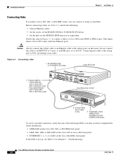
... router installation: • LINK LED on the Cisco 801, 802, or 802 IDSL back panel. • LKØ, LK1, LK2, or LK3 LED on the Cisco 803 or Cisco 804 front panel. • ETHERNET 1, 2, 3, or 4 LED on the Cisco 804 IDSL front panel. Follow the steps in Chapter 3, "Troubleshooting." This figure shows a Cisco 803 router with four Ethernet ports. Figure 2-1 Connecting a Hub 1. Connecting the cable to a Cisco 800 series ISDN or IDSL router. If applicable, check setting...
... router installation: • LINK LED on the Cisco 801, 802, or 802 IDSL back panel. • LKØ, LK1, LK2, or LK3 LED on the Cisco 803 or Cisco 804 front panel. • ETHERNET 1, 2, 3, or 4 LED on the Cisco 804 IDSL front panel. Follow the steps in Chapter 3, "Troubleshooting." This figure shows a Cisco 803 router with four Ethernet ports. Figure 2-1 Connecting a Hub 1. Connecting the cable to a Cisco 800 series ISDN or IDSL router. If applicable, check setting...
Hardware Installation Guide
Page 31
... T 0 1 2 3 Cisco 803 CONSOLE ISDN S/T PHONE 1 2 2. Caution Always connect the yellow cable or an Ethernet cable to a Cisco 800 series ISDN or IDSL router, follow the steps in Chapter 3, "Troubleshooting." 78-5373-04 Cisco 800 Series Routers Hardware Installation Guide 2-9 Set HUB/NO HUB or TO HUB/TO PC button. PC ETH SER 0 OK LAN 11675 AUX 3. Ensure that one of these devices to the yellow ports on the Cisco 804 IDSL front panel. Do...
... T 0 1 2 3 Cisco 803 CONSOLE ISDN S/T PHONE 1 2 2. Caution Always connect the yellow cable or an Ethernet cable to a Cisco 800 series ISDN or IDSL router, follow the steps in Chapter 3, "Troubleshooting." 78-5373-04 Cisco 800 Series Routers Hardware Installation Guide 2-9 Set HUB/NO HUB or TO HUB/TO PC button. PC ETH SER 0 OK LAN 11675 AUX 3. Ensure that one of these devices to the yellow ports on the Cisco 804 IDSL front panel. Do...
Hardware Installation Guide
Page 42
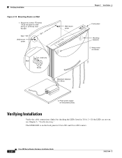
... panel Mounting brackets 2. The LINK LED is on screws. 3. Hang router on the back panel of Cisco 801 and Cisco 802 routers. 2-20 Cisco 800 Series Routers Hardware Installation Guide 78-5373-04 Secure two screws 7 5 8 inches (19.35 cm) apart in a wall and 1 8 in. (0.32 cm) from the wall. 758 in. (19.35 cm) Wall Wall-mount screw Wall-mount screw Wall 1 8 in Table 2-4. Place power supply on , see Chapter 3, "Troubleshooting...
... panel Mounting brackets 2. The LINK LED is on screws. 3. Hang router on the back panel of Cisco 801 and Cisco 802 routers. 2-20 Cisco 800 Series Routers Hardware Installation Guide 78-5373-04 Secure two screws 7 5 8 inches (19.35 cm) apart in a wall and 1 8 in. (0.32 cm) from the wall. 758 in. (19.35 cm) Wall Wall-mount screw Wall-mount screw Wall 1 8 in Table 2-4. Place power supply on , see Chapter 3, "Troubleshooting...

Hardware Installation Guide
Page 47
... of North America, contact your Cisco reseller. No link to Cisco 801 and Cisco 803 Routers" section in the following tasks in Chapter 2, "Installation." 78-5373-04 Cisco 800 Series Routers Hardware Installation Guide 3-3 Improperly connected cable. - Check the cable information in Table 2-2 in Chapter 2, "Installation." • Check specifications in Table B-13 and Table B-14 in Chapter 2, "Installation." • Improperly functioning network interface card (NIC) on the front panel is off .) • A cable-related problem: Perform the following order: -
... of North America, contact your Cisco reseller. No link to Cisco 801 and Cisco 803 Routers" section in the following tasks in Chapter 2, "Installation." 78-5373-04 Cisco 800 Series Routers Hardware Installation Guide 3-3 Improperly connected cable. - Check the cable information in Table 2-2 in Chapter 2, "Installation." • Check specifications in Table B-13 and Table B-14 in Chapter 2, "Installation." • Improperly functioning network interface card (NIC) on the front panel is off .) • A cable-related problem: Perform the following order: -
Hardware Installation Guide
Page 69
Index S S/T interface A-1 safety warnings 2-2 server, connecting 2-9 settings, network devices 2-6 to 2-7 specifications cabling B-6 system B-1 startup problems 3-2 T table mounting 2-18 telephone connecting 2-14, 2-15 ports described 1-2 illustrated 1-5, 1-6 temperature specifications B-1 terminal, connecting 2-17 TO HUB/TO PC button illustrated 1-6 to 1-7 settings 2-6 to 2-20 warnings, installation 2-2 weight specifications B-1 workstation, connecting 2-9 U U interface A-1 United Kingdom master sockets 2-16 78-5373-04 Cisco 800 Series Routers Hardware Installation Guide IN-3 to 2-4 V ...
Index S S/T interface A-1 safety warnings 2-2 server, connecting 2-9 settings, network devices 2-6 to 2-7 specifications cabling B-6 system B-1 startup problems 3-2 T table mounting 2-18 telephone connecting 2-14, 2-15 ports described 1-2 illustrated 1-5, 1-6 temperature specifications B-1 terminal, connecting 2-17 TO HUB/TO PC button illustrated 1-6 to 1-7 settings 2-6 to 2-20 warnings, installation 2-2 weight specifications B-1 workstation, connecting 2-9 U U interface A-1 United Kingdom master sockets 2-16 78-5373-04 Cisco 800 Series Routers Hardware Installation Guide IN-3 to 2-4 V ...


