Administration Guide
Page 2
...2 Getting to Know the SFE2010/SFE2010P 2 SFE2010/P Front Panel 2 SFE2010/P Back Panel 4 3 Connecting Devices 5 Sample Network Configuration 5 Maximum Cabling Distances 5 Before You Install the Switch... 6 Placement Options 6 ...Management 28 IP Configuration 29 File Management 43 Restore System Default Settings 46 Reset to Factory Settings 46 Reboot System 46 Stack Configuration 47 Port Status 47 Port Status 48 PoE Status 48 Port Configuration 49 Port Settings 49 PoE Settings 50 System Mode (Layer 2 / Layer 3) Selection 51 Help 52 Logout 53 SFE2010...
...2 Getting to Know the SFE2010/SFE2010P 2 SFE2010/P Front Panel 2 SFE2010/P Back Panel 4 3 Connecting Devices 5 Sample Network Configuration 5 Maximum Cabling Distances 5 Before You Install the Switch... 6 Placement Options 6 ...Management 28 IP Configuration 29 File Management 43 Restore System Default Settings 46 Reset to Factory Settings 46 Reboot System 46 Stack Configuration 47 Port Status 47 Port Status 48 PoE Status 48 Port Configuration 49 Port Settings 49 PoE Settings 50 System Mode (Layer 2 / Layer 3) Selection 51 Help 52 Logout 53 SFE2010...

Administration Guide
Page 5
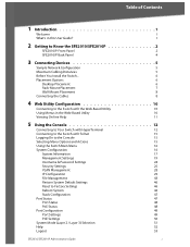
... operating properly. A green MST LED indicates that the cooling fan has failed. On the SFE2010, a green Speed LED indicates that affordably expand the capability of the Linksys system. The SFE2010 and SFE2010P are 48-port, layer-2 Ethernet switches that the port is actively sending or receiving data over Ethernet cable. The green Act/Link...
... operating properly. A green MST LED indicates that the cooling fan has failed. On the SFE2010, a green Speed LED indicates that affordably expand the capability of the Linksys system. The SFE2010 and SFE2010P are 48-port, layer-2 Ethernet switches that the port is actively sending or receiving data over Ethernet cable. The green Act/Link...
Administration Guide
Page 15
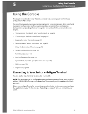
... the Enter key. Before you use HyperTerminal to connect to your switch for basic configuration of the switch and management of your network.This chapter describes console interface configuration. Telnet to Your Switch with HyperTerminal You can also be configured through the web utility, ... (see page 49) • System Mode (Layer 2 / Layer 3) Selection (see page 51) • Help (see page 52) • Logout (see page 53) Connecting to the switch IP address 192.168.1.254. SFE2010/SFE2010P Administration Guide 12 The switch features a menu-driven console interface for the first...
... the Enter key. Before you use HyperTerminal to connect to your switch for basic configuration of the switch and management of your network.This chapter describes console interface configuration. Telnet to Your Switch with HyperTerminal You can also be configured through the web utility, ... (see page 49) • System Mode (Layer 2 / Layer 3) Selection (see page 51) • Help (see page 52) • Logout (see page 53) Connecting to the switch IP address 192.168.1.254. SFE2010/SFE2010P Administration Guide 12 The switch features a menu-driven console interface for the first...
Administration Guide
Page 19
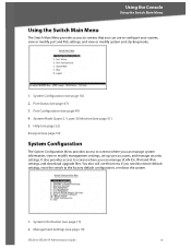
... Switch Main Menu provides access to screens that you can manage system information, view or modify management settings, set up user accounts, and manage security settings. System Mode (Layer 2 / Layer 3) Selection (see page 53) System Configuration The System Configuration Menu provides access to the factory default configuration, or reboot the system. 1. System Information (see page 19) SFE2010...
... Switch Main Menu provides access to screens that you can manage system information, view or modify management settings, set up user accounts, and manage security settings. System Mode (Layer 2 / Layer 3) Selection (see page 53) System Configuration The System Configuration Menu provides access to the factory default configuration, or reboot the system. 1. System Information (see page 19) SFE2010...
Administration Guide
Page 54
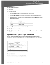
... to the field, and then press the Space Bar until the desired setting appears. SFE2010/SFE2010P Administration Guide 51 Select Edit. 2. System Mode. Using the Console System Mode (Layer 2 / Layer 3) Selection To configure the PoE settings: 1. b. Press the right arrow key to... move the cursor to the Action list. 4. System Mode (Layer 2 / Layer 3) Selection You can also configure stacking mode from one field to specify whether the Ethernet switch is operating in Layer 2 or Layer 3 mode. Field Priority Enable Settings Low, High, or Critical Enable or Disable...
... to the field, and then press the Space Bar until the desired setting appears. SFE2010/SFE2010P Administration Guide 51 Select Edit. 2. System Mode. Using the Console System Mode (Layer 2 / Layer 3) Selection To configure the PoE settings: 1. b. Press the right arrow key to... move the cursor to the Action list. 4. System Mode (Layer 2 / Layer 3) Selection You can also configure stacking mode from one field to specify whether the Ethernet switch is operating in Layer 2 or Layer 3 mode. Field Priority Enable Settings Low, High, or Critical Enable or Disable...
Administration Guide
Page 55
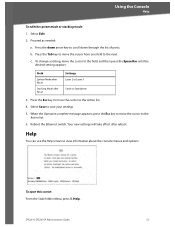
...the field, and then press the Space Bar until the desired setting appears. To open this screen: From the Switch Main Menu, press 5. b. To change a setting, move the cursor to save your settings 5. When the ... the cursor to view information about the console menus and options. Proceed as needed: a. c. Reboot the Ethernet switch. Select Save to the Action list. 6. Press the down arrow key to the next. Help. Using the .... Your new settings will take effect after Reset Settings Layer 2 or Layer 3 Stack or Standalone 3. SFE2010/SFE2010P Administration Guide 52
...the field, and then press the Space Bar until the desired setting appears. To open this screen: From the Switch Main Menu, press 5. b. To change a setting, move the cursor to save your settings 5. When the ... the cursor to view information about the console menus and options. Proceed as needed: a. c. Reboot the Ethernet switch. Select Save to the Action list. 6. Press the down arrow key to the next. Help. Using the .... Your new settings will take effect after Reset Settings Layer 2 or Layer 3 Stack or Standalone 3. SFE2010/SFE2010P Administration Guide 52
Administration Guide
Page 63
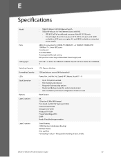
....1Q Tag-based VLANs Protocol-based VLAN Management VLAN Multicast TV VLAN Private VLAN Edge (PVE) GVRP Head of layer 3 traffic SFE2010/SFE2010P Administration Guide 60 E Specifications Model Ports Cabling Type Switching Capacity Forwarding Capacity LEDs Stack Operation Buttons Layer 2 options Layer 3 options • SFE2010 48-port 10/100 Ethernet Switch • SFE2010P 48-port 10/ 100 Ethernet...
....1Q Tag-based VLANs Protocol-based VLAN Management VLAN Multicast TV VLAN Private VLAN Edge (PVE) GVRP Head of layer 3 traffic SFE2010/SFE2010P Administration Guide 60 E Specifications Model Ports Cabling Type Switching Capacity Forwarding Capacity LEDs Stack Operation Buttons Layer 2 options Layer 3 options • SFE2010 48-port 10/100 Ethernet Switch • SFE2010P 48-port 10/ 100 Ethernet...
Administration Guide
Page 64
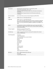
... support for traps SNMP version 1, 2c, 3 with a network analyzer or RMON probe Traceroute Single IP Management Secure Socket Layer (SSL) security for enhanced traffic management, monitoring, and analysis. RADIUS Authentication. MD5 Hash Guest VLAN Single/Multiple Host mode SFE2010/SFE2010P Administration Guide 61 Environment Web User Interface SNMP SNMP MIBs RMON Firmware Upgrade Port...
... support for traps SNMP version 1, 2c, 3 with a network analyzer or RMON probe Traceroute Single IP Management Secure Socket Layer (SSL) security for enhanced traffic management, monitoring, and analysis. RADIUS Authentication. MD5 Hash Guest VLAN Single/Multiple Host mode SFE2010/SFE2010P Administration Guide 61 Environment Web User Interface SNMP SNMP MIBs RMON Firmware Upgrade Port...
