Administration Guide
Page 2
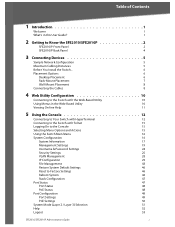
...2 Getting to Know the SFE2010/SFE2010P 2 SFE2010/P Front Panel 2 SFE2010/P Back Panel 4 3 Connecting Devices 5 Sample Network Configuration 5 Maximum Cabling Distances 5 Before You Install the Switch... 6 Placement Options 6 ...Management 28 IP Configuration 29 File Management 43 Restore System Default Settings 46 Reset to Factory Settings 46 Reboot System 46 Stack Configuration 47 Port Status 47 Port Status 48 PoE Status 48 Port Configuration 49 Port Settings 49 PoE Settings 50 System Mode (Layer 2 / Layer 3) Selection 51 Help 52 Logout 53 SFE2010...
...2 Getting to Know the SFE2010/SFE2010P 2 SFE2010/P Front Panel 2 SFE2010/P Back Panel 4 3 Connecting Devices 5 Sample Network Configuration 5 Maximum Cabling Distances 5 Before You Install the Switch... 6 Placement Options 6 ...Management 28 IP Configuration 29 File Management 43 Restore System Default Settings 46 Reset to Factory Settings 46 Reboot System 46 Stack Configuration 47 Port Status 47 Port Status 48 PoE Status 48 Port Configuration 49 Port Settings 49 PoE Settings 50 System Mode (Layer 2 / Layer 3) Selection 51 Help 52 Logout 53 SFE2010...
Administration Guide
Page 5
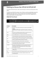
...the corresponding port with an attached device. These two versions are 48-port, layer-2 Ethernet switches that the port is connected and operating properly. A green FAN LED lights up to indicate the status of the switch. SFE2010/P Front Panel Feature Reset LEDs PWR FAN RPS MST Stack ...red FAN LED indicates that port. The Act (Activity) LEDs flash to indicate that the Switch is actively sending or receiving data over -Ethernet (PoE) which can be lost. The SFE2010 and SFE2010P are functionally identical except the SFE2010P model offers Power-over that the cooling fan ...
...the corresponding port with an attached device. These two versions are 48-port, layer-2 Ethernet switches that the port is connected and operating properly. A green FAN LED lights up to indicate the status of the switch. SFE2010/P Front Panel Feature Reset LEDs PWR FAN RPS MST Stack ...red FAN LED indicates that port. The Act (Activity) LEDs flash to indicate that the Switch is actively sending or receiving data over -Ethernet (PoE) which can be lost. The SFE2010 and SFE2010P are functionally identical except the SFE2010P model offers Power-over that the cooling fan ...
Administration Guide
Page 6
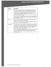
Getting to Know the SFE2010/SFE2010P Feature 1-48 G1-G2 miniGBIC1/2 Description The Switch is equipped with an RJ-45 connector. The MGBSX1 and the MGBLH1 require fiber cabling with LC connectors, while the MGBT1 requires a Category 5e Ethernet cable with 48 auto-sensing, Ethernet (802.3) network ports, which support network speeds of 15.4W...
Getting to Know the SFE2010/SFE2010P Feature 1-48 G1-G2 miniGBIC1/2 Description The Switch is equipped with an RJ-45 connector. The MGBSX1 and the MGBLH1 require fiber cabling with LC connectors, while the MGBT1 requires a Category 5e Ethernet cable with 48 auto-sensing, Ethernet (802.3) network ports, which support network speeds of 15.4W...
Administration Guide
Page 50
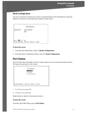
Stack Configuration. SFE2010/SFE2010P Administration Guide 47 By default, ID numbers are automatically assigned to each port on the switch. 1. System Configuration. 2. Port Status (see page 48) 0.Back (Select to return to specify the Stack ID for each device. From the Switch Main Menu, select 1. Port Status The Port Status menu provides access to screens...
Stack Configuration. SFE2010/SFE2010P Administration Guide 47 By default, ID numbers are automatically assigned to each port on the switch. 1. System Configuration. 2. Port Status (see page 48) 0.Back (Select to return to specify the Stack ID for each device. From the Switch Main Menu, select 1. Port Status The Port Status menu provides access to screens...
Administration Guide
Page 51
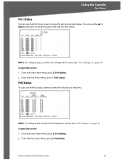
... scroll through all the ports on page 49. NOTE: To configure ports, use the PoE Configuration screen. Port Status. 2. Poe Status. SFE2010/SFE2010P Administration Guide 48 See "Port Settings," on the switch. From the Port Status Menu, press 1. To open this screen: 1. Port Status. 2. PoE Status You can use the Port Status screen..., press 2. Using the Console Port Status Port Status You can use the PoE Status screen to view the PoE status of the ports. From the Switch Main Menu, press 2. From the...
... scroll through all the ports on page 49. NOTE: To configure ports, use the PoE Configuration screen. Port Status. 2. Poe Status. SFE2010/SFE2010P Administration Guide 48 See "Port Settings," on the switch. From the Port Status Menu, press 1. To open this screen: 1. Port Status. 2. PoE Status You can use the Port Status screen..., press 2. Using the Console Port Status Port Status You can use the PoE Status screen to view the PoE status of the ports. From the Switch Main Menu, press 2. From the...
Administration Guide
Page 63
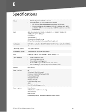
... Forwarding Capacity LEDs Stack Operation Buttons Layer 2 options Layer 3 options • SFE2010 48-port 10/100 Ethernet Switch • SFE2010P 48-port 10/ 100 Ethernet Switch with PoE • IEEE 802.3af PoE on delivered over any of the 48 10/100 ports • Power budget allows for max power of 15.4W to a FE port... IPv4 and IPv6 Forwarding in stack Reset Button 8K 256 active VLANs (4096 range) Port-based and 802.1Q Tag-based VLANs Protocol-based VLAN Management VLAN Multicast TV VLAN Private VLAN Edge (PVE) GVRP Head of layer 3 traffic...
... Forwarding Capacity LEDs Stack Operation Buttons Layer 2 options Layer 3 options • SFE2010 48-port 10/100 Ethernet Switch • SFE2010P 48-port 10/ 100 Ethernet Switch with PoE • IEEE 802.3af PoE on delivered over any of the 48 10/100 ports • Power budget allows for max power of 15.4W to a FE port... IPv4 and IPv6 Forwarding in stack Reset Button 8K 256 active VLANs (4096 range) Port-based and 802.1Q Tag-based VLANs Protocol-based VLAN Management VLAN Multicast TV VLAN Private VLAN Edge (PVE) GVRP Head of layer 3 traffic...

