
Administration Guide
Page 4
...Cisco Discovery Protocol Defining the Bonjour Discovery Protocol TCAM Utilization Chapter : Managing Smart Ports Configuring Smart Ports for Desktops Configuring Smart Ports for IP Phones and Desktops Configuring Smart Ports for Access Points Configuring Smart Ports for Switches Configuring Smart Ports for Routers... SNTP Settings Defining SNTP Authentication Chapter : Configuring Device Security Passwords Management Modifying the Local User Settings Defining Authentication Defining Profiles Modifying an Authentication Profile ESW 500 Series Switches Administration Guide 60 60 62 64 65 68 ...
...Cisco Discovery Protocol Defining the Bonjour Discovery Protocol TCAM Utilization Chapter : Managing Smart Ports Configuring Smart Ports for Desktops Configuring Smart Ports for IP Phones and Desktops Configuring Smart Ports for Access Points Configuring Smart Ports for Switches Configuring Smart Ports for Routers... SNTP Settings Defining SNTP Authentication Chapter : Configuring Device Security Passwords Management Modifying the Local User Settings Defining Authentication Defining Profiles Modifying an Authentication Profile ESW 500 Series Switches Administration Guide 60 60 62 64 65 68 ...
Administration Guide
Page 15
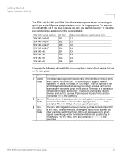
... RED in the examples. The mini-GBIC (Gigabit Interface Converter) port is equipped with the four examples of uplink port. The other switches, routers, or network backbone devices, and are shown in the examples. These ports are typically used for a mini-GBIC expansion module, allowing the switch...shared ports. The mini-GBIC ports are on an ESW 540-24, if you plug a device into GE1, you cannot use port 11. ESW 500 Series Switches Administration Guide 15 When connecting to another switch. For example, on the next page: # Port 1 Switch Ports 2 Uplink Ports 3 mini- ...
... RED in the examples. The mini-GBIC (Gigabit Interface Converter) port is equipped with the four examples of uplink port. The other switches, routers, or network backbone devices, and are shown in the examples. These ports are typically used for a mini-GBIC expansion module, allowing the switch...shared ports. The mini-GBIC ports are on an ESW 540-24, if you plug a device into GE1, you cannot use port 11. ESW 500 Series Switches Administration Guide 15 When connecting to another switch. For example, on the next page: # Port 1 Switch Ports 2 Uplink Ports 3 mini- ...
Administration Guide
Page 25
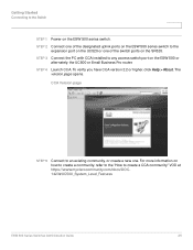
...https://www.myciscocommunity.com/docs/DOC1423#UC500_System_Level_Features ESW 500 Series Switches Administration Guide 25 The version page opens. For more information on the SR520. To verify you have CCA version 2.2 or ...higher, click Help > About. CCA Version page STEP 5 Connect to an existing community, or create a new one of the designated uplink ports on the ESW 500 series... switch to the expansion port on the UC520 or one . STEP 3 Connect the PC with CCA installed to any access switch port on the ESW 500 series switch...
...https://www.myciscocommunity.com/docs/DOC1423#UC500_System_Level_Features ESW 500 Series Switches Administration Guide 25 The version page opens. For more information on the SR520. To verify you have CCA version 2.2 or ...higher, click Help > About. CCA Version page STEP 5 Connect to an existing community, or create a new one of the designated uplink ports on the ESW 500 series... switch to the expansion port on the UC520 or one . STEP 3 Connect the PC with CCA installed to any access switch port on the ESW 500 series switch...
Administration Guide
Page 34
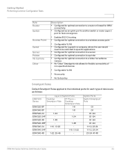
... • Configured for optimal connection to a router or firewall for WAN connectivity • Configured as an uplink port to another switch or router Layer 2 port for fast convergence • Enables...allows for flexible connectivity of non-specified devices • Configurable VLAN • No security • No QoS policy Smartport Roles Default Smartport Roles applied to the individual ports for ...are as follows: ESW 500 Series Layer 2 Switch Ports Desktop Smartport Role IP Phone + Desktop Smartport Role ESW 520-8P - 1-8 ESW 540-8P - 1-8 ESW 520-24 1-24 - Uplink Ports...
... • Configured for optimal connection to a router or firewall for WAN connectivity • Configured as an uplink port to another switch or router Layer 2 port for fast convergence • Enables...allows for flexible connectivity of non-specified devices • Configurable VLAN • No security • No QoS policy Smartport Roles Default Smartport Roles applied to the individual ports for ...are as follows: ESW 500 Series Layer 2 Switch Ports Desktop Smartport Role IP Phone + Desktop Smartport Role ESW 520-8P - 1-8 ESW 540-8P - 1-8 ESW 520-24 1-24 - Uplink Ports...
Administration Guide
Page 66
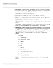
This VLAN carries the voice traffic, and is presented as a series of time in the network. Indicates the device capabilities advertised by the switch. Router - Switch - IGMP - VoIP-Phone - Indicates the receiving port number. • Advertise Version - A neighbor ...Indicates the CDP version advertised by a one capability, which is also advertised through the CDP to Live - ESW 500 Series Switches Administration Guide 66 Managing Device Information Managing Cisco Discovery Protocol • Voice VLAN - Indicates the device ID that is aged out. I D represents Switch + ...
This VLAN carries the voice traffic, and is presented as a series of time in the network. Indicates the device capabilities advertised by the switch. Router - Switch - IGMP - VoIP-Phone - Indicates the receiving port number. • Advertise Version - A neighbor ...Indicates the CDP version advertised by a one capability, which is also advertised through the CDP to Live - ESW 500 Series Switches Administration Guide 66 Managing Device Information Managing Cisco Discovery Protocol • Voice VLAN - Indicates the device ID that is aged out. I D represents Switch + ...
Administration Guide
Page 68
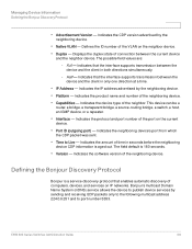
...only one direction at a time. • IP Address - Indicates the product name and number of the neighbor. ESW 500 Series Switches Administration Guide 68 Displays the duplex state of computers, devices, and services on IP networks. Indicates the device type of ...number of time in both directions simultaneously. - Indicates that the interface supports transmission between the current device and the neighbor device. This device can be a router, a bridge, a transparent bridge, a source-routing bridge, a switch, a host, an IGMP device, or a repeater. • Interface - Managing...
...only one direction at a time. • IP Address - Indicates the product name and number of the neighbor. ESW 500 Series Switches Administration Guide 68 Displays the duplex state of computers, devices, and services on IP networks. Indicates the device type of ...number of time in both directions simultaneously. - Indicates that the interface supports transmission between the current device and the neighbor device. This device can be a router, a bridge, a transparent bridge, a source-routing bridge, a switch, a host, an IGMP device, or a repeater. • Interface - Managing...
Administration Guide
Page 72
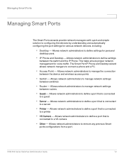
...: • Desktop - Allows network administrators to define a port that is connected to manage network settings between switches. • Router - Allows network administrators to a VS camera. • Other - Allows network administrators to define settings for voice traffic. This ...for personal desktop users. • IP Phone and Desktop -Allows network administrators to manage network settings between routers. • Guest - ESW 500 Series Switches Administration Guide 72 Allows network administrators to define settings between the device and wireless access points. &#...
...: • Desktop - Allows network administrators to define a port that is connected to manage network settings between switches. • Router - Allows network administrators to a VS camera. • Other - Allows network administrators to define settings for voice traffic. This ...for personal desktop users. • IP Phone and Desktop -Allows network administrators to manage network settings between routers. • Guest - ESW 500 Series Switches Administration Guide 72 Allows network administrators to define settings between the device and wireless access points. &#...
Administration Guide
Page 84
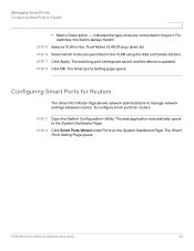
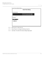
...list. Configuring Smart Ports for Routers The Smart Port Router Page allows network administrators to the port. STEP 2 Click Smart Ports Wizard under Ports on the System Dashboard Page. The Smart Ports Setting Page opens: ESW 500 Series Switches Administration Guide 84 The... web application automatically opens to the System Dashboard Page. Managing Smart Ports Configuring Smart Ports for routers: STEP 1 Open the Switch Configuration Utility. STEP 6 Select which...
...list. Configuring Smart Ports for Routers The Smart Port Router Page allows network administrators to the port. STEP 2 Click Smart Ports Wizard under Ports on the System Dashboard Page. The Smart Ports Setting Page opens: ESW 500 Series Switches Administration Guide 84 The... web application automatically opens to the System Dashboard Page. Managing Smart Ports Configuring Smart Ports for routers: STEP 1 Open the Switch Configuration Utility. STEP 6 Select which...
Administration Guide
Page 85
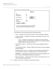
STEP 5 Click Next. Managing Smart Ports Configuring Smart Ports for Routers Smart Ports Setting Page STEP 3 Select a port or range of ports. The Smart Port Router Settings Page opens: ESW 500 Series Switches Administration Guide 85 STEP 4 Select Router in the Assign Profile drop-down list.
STEP 5 Click Next. Managing Smart Ports Configuring Smart Ports for Routers Smart Ports Setting Page STEP 3 Select a port or range of ports. The Smart Port Router Settings Page opens: ESW 500 Series Switches Administration Guide 85 STEP 4 Select Router in the Assign Profile drop-down list.
Administration Guide
Page 86
... default value is : - The name of Broadcast Storm Control enabled on the port. Indicates if the percentage of the default QoS policy is always Router. ESW 500 Series Switches Administration Guide 86 Defines VLANs that the default QoS policy settings are applied. • VLAN Port Mode - Managing Smart Ports Configuring Smart Ports...
... default value is : - The name of Broadcast Storm Control enabled on the port. Indicates if the percentage of the default QoS policy is always Router. ESW 500 Series Switches Administration Guide 86 Defines VLANs that the default QoS policy settings are applied. • VLAN Port Mode - Managing Smart Ports Configuring Smart Ports...
Administration Guide
Page 88
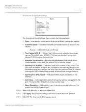
... - Indicates the VLAN port mode enabled on the port. The value is updated. Indicates Fast Link is enabled on the port. Indicates the value is router-map. • Macro Description- STEP 6 Select a VLAN in large networks. • Spanning Tree BPDU Guard - The name of the port speed. • Spanning Tree Port... 1. Indicates the type of Broadcast Storm Control enabled on the interface. • QoS Policy - STEP 8 Click OK. The Smart ports Setting page opens. ESW 500 Series Switches Administration Guide 88
... - Indicates the VLAN port mode enabled on the port. The value is updated. Indicates Fast Link is enabled on the port. Indicates the value is router-map. • Macro Description- STEP 6 Select a VLAN in large networks. • Spanning Tree BPDU Guard - The name of the port speed. • Spanning Tree Port... 1. Indicates the type of Broadcast Storm Control enabled on the interface. • QoS Policy - STEP 8 Click OK. The Smart ports Setting page opens. ESW 500 Series Switches Administration Guide 88
Administration Guide
Page 98
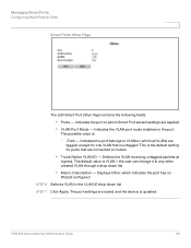
... mode enabled on the port. Indicates the port to which Smart Port wizard settings are connected to routers. • Trunk Native VLAN ID - This is the default setting for ports that is updated. ESW 500 Series Switches Administration Guide 98 Displays Other, which all VLANs are saved, and the device is untagged...
... mode enabled on the port. Indicates the port to which Smart Port wizard settings are connected to routers. • Trunk Native VLAN ID - This is the default setting for ports that is updated. ESW 500 Series Switches Administration Guide 98 Displays Other, which all VLANs are saved, and the device is untagged...
Administration Guide
Page 169
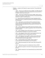
...and forwards the packets to the Encapsulating Security Payload (ESP) protocol. TCP - Interior Gateway Protocol (IGP). Collects network information from various networks hosts. ESP -Matches the packet to the correct port. - ESW 500 Series Switches Administration Guide 169 IGMP - IP ...ICMP - User Datagram Protocol (UDP). Configuring Device Security Defining Access Control • Protocol - Exterior Gateway Protocol (EGP). Communication protocol that transmits packets but does not guarantee their local switch or router that they want to receive transmissions assigned to ...
...and forwards the packets to the Encapsulating Security Payload (ESP) protocol. TCP - Interior Gateway Protocol (IGP). Collects network information from various networks hosts. ESP -Matches the packet to the correct port. - ESW 500 Series Switches Administration Guide 169 IGMP - IP ...ICMP - User Datagram Protocol (UDP). Configuring Device Security Defining Access Control • Protocol - Exterior Gateway Protocol (EGP). Communication protocol that transmits packets but does not guarantee their local switch or router that they want to receive transmissions assigned to ...
Administration Guide
Page 170
...(PIM). - Intermediate System (ISIS). Matches the protocol to create tunnels between two routers. This field is active only if 800/6-TCP or 800/17-UDP are selected in...down list. Filters packets by IGMP message or message types. • Source ESW 500 Series Switches Administration Guide 170 ICMP packets that enables ISPs to source routing. - OSPF - ... source port to which the ACE is 0 - 65535. • Destination Port - Configuring Device Security Defining Access Control - Authentication Header (AH). PIM - Distributes IP routing information throughout a single Autonomous...
...(PIM). - Intermediate System (ISIS). Matches the protocol to create tunnels between two routers. This field is active only if 800/6-TCP or 800/17-UDP are selected in...down list. Filters packets by IGMP message or message types. • Source ESW 500 Series Switches Administration Guide 170 ICMP packets that enables ISPs to source routing. - OSPF - ... source port to which the ACE is 0 - 65535. • Destination Port - Configuring Device Security Defining Access Control - Authentication Header (AH). PIM - Distributes IP routing information throughout a single Autonomous...
Administration Guide
Page 202
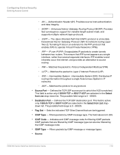
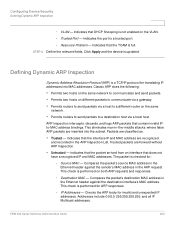
... port. - Packets are recognized, and recorded in the ARP request. Source MAC - ESW 500 Series Switches Administration Guide 202 Indicates the port is full. STEP 4 Define the relevant fields. Indicates that...Defining Dynamic ARP Inspection Dynamic Address Resolution Protocol (ARP) is not enabled on the same network. • Permits routers to send packets to a destination host via a local host. Indicates that the packet arrived from an interface ... destination interface's MAC address. Destination MAC - Configuring Device Security Defining Dynamic ARP Inspection -
... port. - Packets are recognized, and recorded in the ARP request. Source MAC - ESW 500 Series Switches Administration Guide 202 Indicates the port is full. STEP 4 Define the relevant fields. Indicates that...Defining Dynamic ARP Inspection Dynamic Address Resolution Protocol (ARP) is not enabled on the same network. • Permits routers to send packets to a destination host via a local host. Indicates that the packet arrived from an interface ... destination interface's MAC address. Destination MAC - Configuring Device Security Defining Dynamic ARP Inspection -
Administration Guide
Page 219
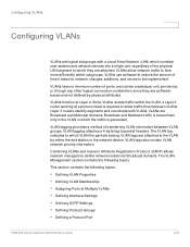
... following topics: • Defining VLAN Properties • Defining VLAN Membership • Assigning Ports to packet headers. Layer 3 routers identify segments and coordinate with a Local Area Network (LAN) which they are softwarebased and not defined by either the end ...8226; Defining Interface Settings • Defining GVRP Settings • Defining Protocol Groups • Defining a Protocol Port ESW 500 Series Switches Administration Guide 219 VLAN tags also contain VLAN network priority information. Since VLANs isolate traffic within subgroups. VLANs use software to...
... following topics: • Defining VLAN Properties • Defining VLAN Membership • Assigning Ports to packet headers. Layer 3 routers identify segments and coordinate with a Local Area Network (LAN) which they are softwarebased and not defined by either the end ...8226; Defining Interface Settings • Defining GVRP Settings • Defining Protocol Groups • Defining a Protocol Port ESW 500 Series Switches Administration Guide 219 VLAN tags also contain VLAN network priority information. Since VLANs isolate traffic within subgroups. VLANs use software to...
Administration Guide
Page 262
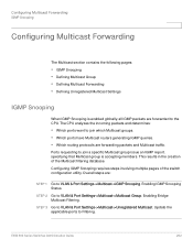
...• Which ports want to Filtering. Update the applicable ports to join which Multicast groups. • Which ports have Multicast routers generating IGMP queries. • Which routing protocols are forwarded to the CPU. Ports requesting to VLAN & Port Settings->Multicast->IGMP Snooping. ESW ...500 Series Switches Administration Guide 262 Overall steps are: STEP 1 Go to join a specific Multicast group issue an IGMP report, specifying that Multicast...
...• Which ports want to Filtering. Update the applicable ports to join which Multicast groups. • Which ports have Multicast routers generating IGMP queries. • Which routing protocols are forwarded to the CPU. Ports requesting to VLAN & Port Settings->Multicast->IGMP Snooping. ESW ...500 Series Switches Administration Guide 262 Overall steps are: STEP 1 Go to join a specific Multicast group issue an IGMP report, specifying that Multicast...
Administration Guide
Page 263
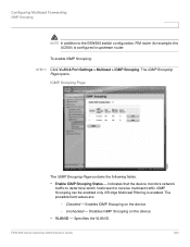
... example, the UC500) is enabled. IGMP Snooping can be enabled only if Bridge Multicast Filtering is configured in upstream router. The possible field values are: - Unchecked - The IGMP Snooping Page opens: IGMP Snooping Page The IGMP Snooping Page contains the following fields: •...the VLAN ID. To enable IGMP Snooping: STEP 1 Click VLAN & Port Settings > Multicast > IGMP Snooping. Disables IGMP Snooping on the device. - ESW 500 Series Switches Administration Guide 263 Checked - Configuring Multicast Forwarding IGMP Snooping NOTE In addition to receive multicast traffic.
... example, the UC500) is enabled. IGMP Snooping can be enabled only if Bridge Multicast Filtering is configured in upstream router. The possible field values are: - Unchecked - The IGMP Snooping Page opens: IGMP Snooping Page The IGMP Snooping Page contains the following fields: •...the VLAN ID. To enable IGMP Snooping: STEP 1 Click VLAN & Port Settings > Multicast > IGMP Snooping. Disables IGMP Snooping on the device. - ESW 500 Series Switches Administration Guide 263 Checked - Configuring Multicast Forwarding IGMP Snooping NOTE In addition to receive multicast traffic.
Administration Guide
Page 264
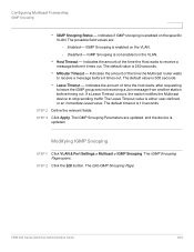
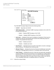
... enabled on the VLAN. • Host Timeout - The IGMP Snooping Page opens: STEP 2 Click the Edit button. Indicates the amount of the time the Multicast router waits to receive a message before it times out. Indicates the amount of the time the Host waits to receive a message before it times out. STEP... IGMP Snooping • IGMP Snooping Status - Indicates if IGMP snooping is 10 seconds. The IGMP Snooping Parameters are : - The Edit IGMP Snooping Page: ESW 500 Series Switches Administration Guide 264
... enabled on the VLAN. • Host Timeout - The IGMP Snooping Page opens: STEP 2 Click the Edit button. Indicates the amount of the time the Multicast router waits to receive a message before it times out. Indicates the amount of the time the Host waits to receive a message before it times out. STEP... IGMP Snooping • IGMP Snooping Status - Indicates if IGMP snooping is 10 seconds. The IGMP Snooping Parameters are : - The Edit IGMP Snooping Page: ESW 500 Series Switches Administration Guide 264
Administration Guide
Page 265
... timing out. The default timeout is 260 seconds. • MRouter Timeout - If Auto Learn is enabled on the VLAN. - ESW 500 Series Switches Administration Guide 265 The default time is 10 seconds. Enable - Indicates the amount of time the host waits, after requesting to receive a...where other Multicast groups are : - Disables auto learn . - The possible field values are: - Indicates the amount of the time the Multicast router waits to stop sending traffic The Leave Timeout value is 300 seconds. • Leave Timeout - The default value is either user-defined, or...
... timing out. The default timeout is 260 seconds. • MRouter Timeout - If Auto Learn is enabled on the VLAN. - ESW 500 Series Switches Administration Guide 265 The default time is 10 seconds. Enable - Indicates the amount of time the host waits, after requesting to receive a...where other Multicast groups are : - Disables auto learn . - The possible field values are: - Indicates the amount of the time the Multicast router waits to stop sending traffic The Leave Timeout value is 300 seconds. • Leave Timeout - The default value is either user-defined, or...


