
Hardware Installation Guide
Page 2
... radio are designed to this document are service marks; If it is an adaptation of a program developed by Cisco Systems, Inc. These specifications are on circuits controlled by different circuit breakers or fuses.) Modifications to provide reasonable protection against harmful interference when...coincidental. Any examples, command display output, and figures included in this manual generates and may cause interference with the specifications in part 15 of Cisco and/or its peripheral devices. All other company. (1002R) Any Internet Protocol (IP) addresses used in this ...
... radio are designed to this document are service marks; If it is an adaptation of a program developed by Cisco Systems, Inc. These specifications are on circuits controlled by different circuit breakers or fuses.) Modifications to provide reasonable protection against harmful interference when...coincidental. Any examples, command display output, and figures included in this manual generates and may cause interference with the specifications in part 15 of Cisco and/or its peripheral devices. All other company. (1002R) Any Internet Protocol (IP) addresses used in this ...

Hardware Installation Guide
Page 5
... 4-4 Speed, Duplex, and Autonegotiation 4-4 Autonegotiation and NIC Cards 4-5 Cabling Distance 4-5 Clearing the Switch IP Address and Configuration 4-5 Locating the Switch Serial Number 4-6 Technical Specifications A-1 Connector and Cable Specifications B-1 Connector Specifications B-1 10/100/1000 Ports B-1 Connecting to 1000BASE-T Devices B-2 SFP Module Ports B-3 Dual-Purpose Ports B-3 Catalyst 2960 Switch Hardware Installation Guide v and 100BASE-TX...
... 4-4 Speed, Duplex, and Autonegotiation 4-4 Autonegotiation and NIC Cards 4-5 Cabling Distance 4-5 Clearing the Switch IP Address and Configuration 4-5 Locating the Switch Serial Number 4-6 Technical Specifications A-1 Connector and Cable Specifications B-1 Connector Specifications B-1 10/100/1000 Ports B-1 Connecting to 1000BASE-T Devices B-2 SFP Module Ports B-3 Dual-Purpose Ports B-3 Catalyst 2960 Switch Hardware Installation Guide v and 100BASE-TX...

Hardware Installation Guide
Page 6
Contents C A P P E N D I X INDEX Console Port B-4 Cable and Adapter Specifications B-4 SFP Module Cable Specifications B-4 Two Twisted-Pair Cable Pinouts B-6 Four Twisted-Pair Cable Pinouts for 1000BASE-T Ports B-6 Crossover Cable and Adapter Pinouts B-7 Identifying a Crossover Cable B-7 Adapter Pinouts B-8 Configuring the ...
Contents C A P P E N D I X INDEX Console Port B-4 Cable and Adapter Specifications B-4 SFP Module Cable Specifications B-4 Two Twisted-Pair Cable Pinouts B-6 Four Twisted-Pair Cable Pinouts for 1000BASE-T Ports B-6 Crossover Cable and Adapter Pinouts B-7 Identifying a Crossover Cable B-7 Adapter Pinouts B-8 Configuring the ...

Hardware Installation Guide
Page 13
...48TC-L switches support all the SFP modules. The 10/100 and 10/100/1000 ports autonegotiate speed and support full-duplex or half-duplex mode. See the compatibility matrix documents for the RPS systems on Cisco.com for an optional Cisco RPS 2300 or Cisco RPS 675 redundant power system that operates on specific... switches, see the Cisco Gigabit Ethernet Transceiver Modules Compatibility Matrix at this Cisco.com URL: http://www.cisco.com/en/US/docs/interfaces_modules...
...48TC-L switches support all the SFP modules. The 10/100 and 10/100/1000 ports autonegotiate speed and support full-duplex or half-duplex mode. See the compatibility matrix documents for the RPS systems on Cisco.com for an optional Cisco RPS 2300 or Cisco RPS 675 redundant power system that operates on specific... switches, see the Cisco Gigabit Ethernet Transceiver Modules Compatibility Matrix at this Cisco.com URL: http://www.cisco.com/en/US/docs/interfaces_modules...

Hardware Installation Guide
Page 21
...if the attached device supports it ) and configures itself accordingly. When you connect the switch to workstations, servers, routers, and Cisco IP Phones, be sure that the cable is , the fastest line speed that both devices support and full-duplex transmission if ...default setting is a straight-through cable. You can also set these ports for the cables are described in Appendix B, "Connector and Cable Specifications." For configuration information for autonegotiation, it senses the speed and duplex settings of the connection. You can use Category 3 or Category 4 ...
...if the attached device supports it ) and configures itself accordingly. When you connect the switch to workstations, servers, routers, and Cisco IP Phones, be sure that the cable is , the fastest line speed that both devices support and full-duplex transmission if ...default setting is a straight-through cable. You can also set these ports for the cables are described in Appendix B, "Connector and Cable Specifications." For configuration information for autonegotiation, it senses the speed and duplex settings of the connection. You can use Category 3 or Category 4 ...

Hardware Installation Guide
Page 23
...activates only one shows the status of the SFP module port. For information about cabling requirements, see Appendix B, "Connector and Cable Specifications." Through an external AC power adapter that connects to the back of the pair at a time. Dual-Purpose Port You can use...more information about configuring speed and duplex settings for a dual-purpose uplink, see your SFP module documentation or the release notes for your Cisco representative. (See Figure 1-22.) OL-7075-09 Catalyst 2960 Switch Hardware Installation Guide 1-13 However, you can configure a dual-purpose ...
...activates only one shows the status of the SFP module port. For information about cabling requirements, see Appendix B, "Connector and Cable Specifications." Through an external AC power adapter that connects to the back of the pair at a time. Dual-Purpose Port You can use...more information about configuring speed and duplex settings for a dual-purpose uplink, see your SFP module documentation or the release notes for your Cisco representative. (See Figure 1-22.) OL-7075-09 Catalyst 2960 Switch Hardware Installation Guide 1-13 However, you can configure a dual-purpose ...
Hardware Installation Guide
Page 31
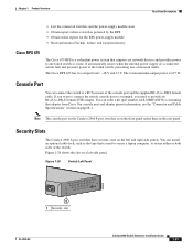
...status reports for the RPS power-supply module • Read and monitor backup, failure, and exception history Cisco RPS 675 The Cisco 675 RPS is a redundant power system that adapter from Cisco. The Cisco RPS 675 has two output levels: -48 V and 12 V. Console Port You can install an ...optional cable lock, such as the type that is used to secure a laptop computer, to secure either or both sides of the switch. For console port and adapter pinout information, see the "Connector and Cable Specifications...
...status reports for the RPS power-supply module • Read and monitor backup, failure, and exception history Cisco RPS 675 The Cisco 675 RPS is a redundant power system that adapter from Cisco. The Cisco RPS 675 has two output levels: -48 V and 12 V. Console Port You can install an ...optional cable lock, such as the type that is used to secure a laptop computer, to secure either or both sides of the switch. For console port and adapter pinout information, see the "Connector and Cable Specifications...
Hardware Installation Guide
Page 36
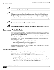
...switch. Do not open. You must always be no longer than 328 feet (100 meters). • The cables meet the specifications in Table B-1 on Power over Ethernet (PoE) circuits if interconnections are made using such interconnection methods, unless the exposed metal ... system malfunction. Statement 1072 Warning No user-serviceable parts inside the chassis, which lists the cable specifications for 1000BASE-X and 100BASE-X SFP modules for Particulate Matter Cisco Ethernet switches are made first and disconnected last. Statement 1073 Warning Installation of suspended particulate matter: ...
...switch. Do not open. You must always be no longer than 328 feet (100 meters). • The cables meet the specifications in Table B-1 on Power over Ethernet (PoE) circuits if interconnections are made using such interconnection methods, unless the exposed metal ... system malfunction. Statement 1072 Warning No user-serviceable parts inside the chassis, which lists the cable specifications for 1000BASE-X and 100BASE-X SFP modules for Particulate Matter Cisco Ethernet switches are made first and disconnected last. Statement 1073 Warning Installation of suspended particulate matter: ...
Hardware Installation Guide
Page 37
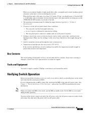
...such as radios, power lines, and fluorescent lighting fixtures. Note When you connect the RPS to the switch, put the RPS in Appendix A, "Technical Specifications." • Clearance to insert an inline optical attenuator in a rack, on a wall, or on a table or shelf, you should power on...09 Catalyst 2960 Switch Hardware Installation Guide 2-5 The rear-panel power connector is within the ranges listed in standby mode. If your Cisco representative or reseller for more information. Verifying Switch Operation Before you use shorter lengths of the power cord to the same AC power...
...such as radios, power lines, and fluorescent lighting fixtures. Note When you connect the RPS to the switch, put the RPS in Appendix A, "Technical Specifications." • Clearance to insert an inline optical attenuator in a rack, on a wall, or on a table or shelf, you should power on...09 Catalyst 2960 Switch Hardware Installation Guide 2-5 The rear-panel power connector is within the ranges listed in standby mode. If your Cisco representative or reseller for more information. Verifying Switch Operation Before you use shorter lengths of the power cord to the same AC power...

Hardware Installation Guide
Page 38
...turns amber. Install the switch in a rack, on a wall, on a table, or on a shelf as described in this section might not show your specific switch; The illustrations in the "Installing the Switch" section on , it is the only unit in the rack. • When mounting this unit in ...the rack. and 48-port switches. Statement 1006 Catalyst 2960 Switch Hardware Installation Guide 2-6 OL-7075-09 Call Cisco technical support representative if your safety: • This unit should be mounted at the bottom of tests that runs automatically to ensure that the ...
...turns amber. Install the switch in a rack, on a wall, on a table, or on a shelf as described in this section might not show your specific switch; The illustrations in the "Installing the Switch" section on , it is the only unit in the rack. • When mounting this unit in ...the rack. and 48-port switches. Statement 1006 Catalyst 2960 Switch Hardware Installation Guide 2-6 OL-7075-09 Call Cisco technical support representative if your safety: • This unit should be mounted at the bottom of tests that runs automatically to ensure that the ...

Hardware Installation Guide
Page 47
... the topology and searches for this feature, see the switch software configuration guide or the switch command reference. See the "SFP Module Cable Specifications" section on the front of SFP modules that the Catalyst 2960 switch supports. Chapter 2 Switch Installation (24- Step 1 When connecting to... workstations, servers, routers, and Cisco IP Phones, connect a straight-through 3 to an RJ-45 connector on when both the switch and the connected device have established link...
... the topology and searches for this feature, see the switch software configuration guide or the switch command reference. See the "SFP Module Cable Specifications" section on the front of SFP modules that the Catalyst 2960 switch supports. Chapter 2 Switch Installation (24- Step 1 When connecting to... workstations, servers, routers, and Cisco IP Phones, connect a straight-through 3 to an RJ-45 connector on when both the switch and the connected device have established link...

Hardware Installation Guide
Page 50
...-Optic SFP Modules" section. For instructions on the SFP module. 2-18 Catalyst 2960 Switch Hardware Installation Guide OL-7075-09 See Appendix B, "Connector and Cable Specifications" for information about how to SFP Modules Chapter 2 Switch Installation (24- Connecting to install or remove an SFP module, see the "Installing and Removing SFP...
...-Optic SFP Modules" section. For instructions on the SFP module. 2-18 Catalyst 2960 Switch Hardware Installation Guide OL-7075-09 See Appendix B, "Connector and Cable Specifications" for information about how to SFP Modules Chapter 2 Switch Installation (24- Connecting to install or remove an SFP module, see the "Installing and Removing SFP...
Hardware Installation Guide
Page 55
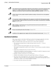
... That You Supply, page 3-4 • Box Contents, page 3-5 • Tools and Equipment, page 3-5 Warnings These warnings are translated into several languages in this chapter is specific to the switch, see Chapter 2, "Switch Installation (24- It also describes how to interpret the power-on self-test (POST) that exceeds the maximum recommended...
... That You Supply, page 3-4 • Box Contents, page 3-5 • Tools and Equipment, page 3-5 Warnings These warnings are translated into several languages in this chapter is specific to the switch, see Chapter 2, "Switch Installation (24- It also describes how to interpret the power-on self-test (POST) that exceeds the maximum recommended...
Hardware Installation Guide
Page 57
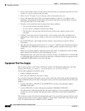
... must always be grounded. When you allow at its maximum temperature 113°F (45°C) and is specific to observe these requirements: • The operating environment must be within the ranges listed in Appendix A, "Technical Specifications." • Airflow around the unit does not exceed 113°F (45°C). Do not open. OL...
... must always be grounded. When you allow at its maximum temperature 113°F (45°C) and is specific to observe these requirements: • The operating environment must be within the ranges listed in Appendix A, "Technical Specifications." • Airflow around the unit does not exceed 113°F (45°C). Do not open. OL...
Hardware Installation Guide
Page 58
...of the switch and prevent them from being accidentally removed. To order a cable guard, contact your Cisco representative and use these conditions - Cable locks are separated on all sides by at least 3 inches...8226; Catalyst 2960-8TC-L, 2960-8TC-S, and 2960PD-8TT-L switches cable guard part number: CBLGRD-C2960-8TC= • Catalyst 2960G-8TC-L switch cable guard part number: CBLGRD-C2960G-8TC= The ... rear panel. • Cabling is less than the cable guide, which lists the cable specifications for 1000BASE-X and 100BASE-X small form-factor (SFP) modules available for the Catalyst 2960 ...
...of the switch and prevent them from being accidentally removed. To order a cable guard, contact your Cisco representative and use these conditions - Cable locks are separated on all sides by at least 3 inches...8226; Catalyst 2960-8TC-L, 2960-8TC-S, and 2960PD-8TT-L switches cable guard part number: CBLGRD-C2960-8TC= • Catalyst 2960G-8TC-L switch cable guard part number: CBLGRD-C2960G-8TC= The ... rear panel. • Cabling is less than the cable guide, which lists the cable specifications for 1000BASE-X and 100BASE-X small form-factor (SFP) modules available for the Catalyst 2960 ...
Hardware Installation Guide
Page 59
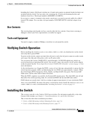
...-to-DB-25 female DTE adapter. See the "Power Input Port (Catalyst 2960PD-8TT-L Switch)" section on Cisco.com describes the box contents. LEDs can receive power from Cisco. If a switch fails POST, the System LED turns amber. After a successful POST, disconnect the power cord... Installation (8-Port Switches) Verifying Switch Operation Installing the Catalyst 2960 8-port switches in a 19-inch rack requires an optional bracket kit that is specific to the Catalyst 2960 8-port switches. You can order a kit (part number ACS-DSBUASYN=) with Mounting Screws), page 3-7 OL-7075-09 ...
...-to-DB-25 female DTE adapter. See the "Power Input Port (Catalyst 2960PD-8TT-L Switch)" section on Cisco.com describes the box contents. LEDs can receive power from Cisco. If a switch fails POST, the System LED turns amber. After a successful POST, disconnect the power cord... Installation (8-Port Switches) Verifying Switch Operation Installing the Catalyst 2960 8-port switches in a 19-inch rack requires an optional bracket kit that is specific to the Catalyst 2960 8-port switches. You can order a kit (part number ACS-DSBUASYN=) with Mounting Screws), page 3-7 OL-7075-09 ...

Hardware Installation Guide
Page 60
... the switch. Note We strongly recommend that you do these steps: Step 1 Step 2 Locate the adhesive strip with or without Mounting Screws) This section is specific to prevent airflow restriction and overheating. and 48-Port Switches)." See the "Connecting to the 10/100 and 10/100/1000 Ports" section on page...
... the switch. Note We strongly recommend that you do these steps: Step 1 Step 2 Locate the adhesive strip with or without Mounting Screws) This section is specific to prevent airflow restriction and overheating. and 48-Port Switches)." See the "Connecting to the 10/100 and 10/100/1000 Ports" section on page...

Hardware Installation Guide
Page 61
... in Figure 3-2. Do not stack switches or place switches side-by -side slots face the front of the desk or shelf after the switch is specific to drill a 1/2-inch (12.7 mm) hole in Figure 3-1. Step 1 Step 2 Locate the screw template.
... in Figure 3-2. Do not stack switches or place switches side-by -side slots face the front of the desk or shelf after the switch is specific to drill a 1/2-inch (12.7 mm) hole in Figure 3-1. Step 1 Step 2 Locate the screw template.

Hardware Installation Guide
Page 62
... MODE CONSOLE 1x 2x 3x 4x 5x 6x 7x 8x Catalyst 296S0eries 1 1 3 204626 2 1 Slides on this way 3 Desk or shelf 2 Screws After the switch is specific to the Catalyst 2960 8-port switches. Connect to the other Catalyst 2960 switches, see Chapter 2, "Switch Installation (24- For information applicable to a 10/100 or...
... MODE CONSOLE 1x 2x 3x 4x 5x 6x 7x 8x Catalyst 296S0eries 1 1 3 204626 2 1 Slides on this way 3 Desk or shelf 2 Screws After the switch is specific to the Catalyst 2960 8-port switches. Connect to the other Catalyst 2960 switches, see Chapter 2, "Switch Installation (24- For information applicable to a 10/100 or...

Hardware Installation Guide
Page 65
... section to install the switch to a wall: Step 1 Step 2 Step 3 Locate the screw template. For the best support of the screw template. The template is specific to the Catalyst 2960 8-port switches. OL-7075-09 Catalyst 2960 Switch Hardware Installation Guide 3-11 Failure to use the correct hardware or to follow...
... section to install the switch to a wall: Step 1 Step 2 Step 3 Locate the screw template. For the best support of the screw template. The template is specific to the Catalyst 2960 8-port switches. OL-7075-09 Catalyst 2960 Switch Hardware Installation Guide 3-11 Failure to use the correct hardware or to follow...
