
Hardware Installation Guide
Page 3
... 2960 PoE Switches) 1-12 SFP Module Slots 1-13 Dual-Purpose Port 1-13 Power Input Port (Catalyst 2960PD-8TT-L Switch) 1-13 LEDs 1-14 System LED 1-15 RPS LED 1-16 Port LEDs and Modes 1-16 Dual-Purpose Port LEDs 1-18 Cable Guard for the Catalyst 2960 8-Port Switches 1-19 Rear Panel Description 1-19 Internal Power Supply 1-20 Cisco...
... 2960 PoE Switches) 1-12 SFP Module Slots 1-13 Dual-Purpose Port 1-13 Power Input Port (Catalyst 2960PD-8TT-L Switch) 1-13 LEDs 1-14 System LED 1-15 RPS LED 1-16 Port LEDs and Modes 1-16 Dual-Purpose Port LEDs 1-18 Cable Guard for the Catalyst 2960 8-Port Switches 1-19 Rear Panel Description 1-19 Internal Power Supply 1-20 Cisco...

Hardware Installation Guide
Page 11
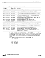
.../100BASE-TX PoE ports and 2 dual-purpose ports OL-7075-09 Catalyst 2960 Switch Hardware Installation Guide 1-1 Product Overview 1 C H A P T E R The Catalyst 2960 switch-also referred to as the switch-is an Ethernet switch to which ...switches outside of the Catalyst 2960 switch. and 48-port Catalyst 2960 switches as in office workspaces and classrooms. See the switch software configuration guide for deployment examples. The Catalyst 2960 8-port compact switches provide the same Ethernet connectivity, but you can connect devices such as workstations, Cisco Wireless Access Points, Cisco...
.../100BASE-TX PoE ports and 2 dual-purpose ports OL-7075-09 Catalyst 2960 Switch Hardware Installation Guide 1-1 Product Overview 1 C H A P T E R The Catalyst 2960 switch-also referred to as the switch-is an Ethernet switch to which ...switches outside of the Catalyst 2960 switch. and 48-port Catalyst 2960 switches as in office workspaces and classrooms. See the switch software configuration guide for deployment examples. The Catalyst 2960 8-port compact switches provide the same Ethernet connectivity, but you can connect devices such as workstations, Cisco Wireless Access Points, Cisco...
Hardware Installation Guide
Page 12
... 2960PD-8TT-L switches are smaller than the other Catalyst 2960 switches. These PoE switches comply with a magnet, have security lock slots, and do not have a fan. See Chapter 3, "Switch Installation (8-Port Switches)," for the installation instructions for more information. See "Catalyst 2960 8-Port Switches" section on page 1-9 for these switch models. They can be mounted with Cisco prestandard PoE and IEEE...
... 2960PD-8TT-L switches are smaller than the other Catalyst 2960 switches. These PoE switches comply with a magnet, have security lock slots, and do not have a fan. See Chapter 3, "Switch Installation (8-Port Switches)," for the installation instructions for more information. See "Catalyst 2960 8-Port Switches" section on page 1-9 for these switch models. They can be mounted with Cisco prestandard PoE and IEEE...

Hardware Installation Guide
Page 14
...; 10/100 Ports, page 1-11 • 10/100/1000 Ports, page 1-11 • PoE Ports (Only Catalyst 2960 PoE Switches), page 1-12 • SFP Module Slots, page 1-13 • Dual-Purpose Port, page 1-13 • Power Input Port (Catalyst 2960PD-8TT-L Switch), page 1-13 • LEDs, page 1-14 • Cable Guard for that is above...
...; 10/100 Ports, page 1-11 • 10/100/1000 Ports, page 1-11 • PoE Ports (Only Catalyst 2960 PoE Switches), page 1-12 • SFP Module Slots, page 1-13 • Dual-Purpose Port, page 1-13 • Power Input Port (Catalyst 2960PD-8TT-L Switch), page 1-13 • LEDs, page 1-14 • Cable Guard for that is above...

Hardware Installation Guide
Page 16
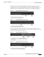
... the pair (port 1) is above the second member (port 2), port 3 is above port 4, and so on the switches are grouped in pairs. Figure 1-5 SYST RPS STAT DUPLX SPEED PoE MODE Catalyst 2960-24PC-L Switch Front Panel 1 2 1X 3 4 5 6 7 8 9 10 11 12 13 14 15 16 17 18 19 ... Installation Guide 1-6 OL-7075-09 The fixed 10/100 ports on the Catalyst 2960-24LC-S switch are PoE ports. Ports 1 to 8 on the Catalyst 2960-24PC-L and 2960-24PC-S switches are PoE ports. See Figure 1-5 and Figure 1-6. Front Panel Description Chapter 1 Product Overview Catalyst 2960-24PC-L, 2960-24PC-S, 2960-...
... the pair (port 1) is above the second member (port 2), port 3 is above port 4, and so on the switches are grouped in pairs. Figure 1-5 SYST RPS STAT DUPLX SPEED PoE MODE Catalyst 2960-24PC-L Switch Front Panel 1 2 1X 3 4 5 6 7 8 9 10 11 12 13 14 15 16 17 18 19 ... Installation Guide 1-6 OL-7075-09 The fixed 10/100 ports on the Catalyst 2960-24LC-S switch are PoE ports. Ports 1 to 8 on the Catalyst 2960-24PC-L and 2960-24PC-S switches are PoE ports. See Figure 1-5 and Figure 1-6. Front Panel Description Chapter 1 Product Overview Catalyst 2960-24PC-L, 2960-24PC-S, 2960-...
Hardware Installation Guide
Page 17
For more information about the dual-purpose port, see the "Dual-Purpose Port" section on the Catalyst 2960-24LT-L switch are PoE ports. Ports 1 to set the connector type for that is, 10/100/1000 ports 1 and 2 can use either the SFP module or the RJ-45 ...connector for these ports. See Figure 1-10, Figure 1-11, and Figure 1-12. 204642 Figure 1-10 Catalyst 2960-24LT-L Switch Front Panel SYST RPS STAT DUPLX SPEED PoE MODE 1 2 1X 34 5 6 7 8 9 10 11 12 13 14 15 16 17 18 19 20 21 22 23 24 Catalyst 2960 Series...
For more information about the dual-purpose port, see the "Dual-Purpose Port" section on the Catalyst 2960-24LT-L switch are PoE ports. Ports 1 to set the connector type for that is, 10/100/1000 ports 1 and 2 can use either the SFP module or the RJ-45 ...connector for these ports. See Figure 1-10, Figure 1-11, and Figure 1-12. 204642 Figure 1-10 Catalyst 2960-24LT-L Switch Front Panel SYST RPS STAT DUPLX SPEED PoE MODE 1 2 1X 34 5 6 7 8 9 10 11 12 13 14 15 16 17 18 19 20 21 22 23 24 Catalyst 2960 Series...

Hardware Installation Guide
Page 18
...1 2 12X 14X 24X 26X 36X 38X 3 4 48X 1 2 205644 1 10/100 PoE ports 2 10/100/1000 uplink ports 3 SFP module slots Figure 1-14 Catalyst 2960-48PST-S Switch Front Panel 3 206732 1 2 1 10/100 PoE ports 2 10/100/1000 uplink ports 3 SFP module slots Catalyst 2960G-24TC-L and Catalyst ... 2), port 3 is above port 4, and so on the Catalyst 2960G-24TC-L and Catalyst 2960G-48TC-L switches are PoE ports. Front Panel Description Chapter 1 Product Overview Figure 1-12 Catalyst 2960-48TT-L Switch Front Panel 204609 SYST RPS STAT DUPLX SPEED MODE 1 2 1 10/100 ports 2 10/100/1000 ...
...1 2 12X 14X 24X 26X 36X 38X 3 4 48X 1 2 205644 1 10/100 PoE ports 2 10/100/1000 uplink ports 3 SFP module slots Figure 1-14 Catalyst 2960-48PST-S Switch Front Panel 3 206732 1 2 1 10/100 PoE ports 2 10/100/1000 uplink ports 3 SFP module slots Catalyst 2960G-24TC-L and Catalyst ... 2), port 3 is above port 4, and so on the Catalyst 2960G-24TC-L and Catalyst 2960G-48TC-L switches are PoE ports. Front Panel Description Chapter 1 Product Overview Figure 1-12 Catalyst 2960-48TT-L Switch Front Panel 204609 SYST RPS STAT DUPLX SPEED MODE 1 2 1 10/100 ports 2 10/100/1000 ...

Hardware Installation Guide
Page 19
...204611 Catalyst 2960 8-Port Switches These sections describe the Catalyst 2960 8-port switches: • Catalyst 2960PD-8TT-L Switch, page 1-9 • Catalyst 2960-8TC-S, Catalyst 2960-8TC-L, and Catalyst 2960G-8TC -L Switches, page 1-10 Catalyst 2960PD-8TT-L Switch The Catalyst 2960PD-8TT-L (Figure 1-17) switch front panel has a console...that is connected through the rear panel. 204643 Figure 1-17 Catalyst 2960PD-8TT-L Switch Front Panel SYST STAT DPLX SPD 1x 2x 3x 4x 5x 6x 7x 8x CONSOLE MODE Catalyst 2960 Series 1 PoE INPUT 1 2 3 1 Console port 3 10/100/1000 power input...
...204611 Catalyst 2960 8-Port Switches These sections describe the Catalyst 2960 8-port switches: • Catalyst 2960PD-8TT-L Switch, page 1-9 • Catalyst 2960-8TC-S, Catalyst 2960-8TC-L, and Catalyst 2960G-8TC -L Switches, page 1-10 Catalyst 2960PD-8TT-L Switch The Catalyst 2960PD-8TT-L (Figure 1-17) switch front panel has a console...that is connected through the rear panel. 204643 Figure 1-17 Catalyst 2960PD-8TT-L Switch Front Panel SYST STAT DPLX SPD 1x 2x 3x 4x 5x 6x 7x 8x CONSOLE MODE Catalyst 2960 Series 1 PoE INPUT 1 2 3 1 Console port 3 10/100/1000 power input...
Hardware Installation Guide
Page 22
... an IEEE 802.3af-compliant powered device, a Cisco prestandard IP phone, or a Cisco prestandard Cisco access point, is connected. • You also can connect a Cisco IP Phone or Cisco Aironet Access Point to a Catalyst 2960 PoE switch 10/100 port and to it. For information about configuring and monitoring PoE ports, see the documentation that do not fully...
... an IEEE 802.3af-compliant powered device, a Cisco prestandard IP phone, or a Cisco prestandard Cisco access point, is connected. • You also can connect a Cisco IP Phone or Cisco Aironet Access Point to a Catalyst 2960 PoE switch 10/100 port and to it. For information about configuring and monitoring PoE ports, see the documentation that do not fully...
Hardware Installation Guide
Page 24
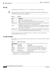
...PoE switches have an RPS connector or an RPS LED: Catalyst 2960-24-S, Catalyst 2960-24TC-S, Catalyst 2960-48TT-S, Catalyst 2960-48TC-S. 1-14 Catalyst 2960 Switch Hardware Installation Guide OL-7075-09 Figure 1-23 shows the switch LEDs and the Mode button that you use the switch LEDs to monitor switch... activity and its performance. The four Catalyst 2960 8-port switches and these models do not have a PoE LED. All LEDs are visible through the GUI ...
...PoE switches have an RPS connector or an RPS LED: Catalyst 2960-24-S, Catalyst 2960-24TC-S, Catalyst 2960-48TT-S, Catalyst 2960-48TC-S. 1-14 Catalyst 2960 Switch Hardware Installation Guide OL-7075-09 Figure 1-23 shows the switch LEDs and the Mode button that you use the switch LEDs to monitor switch... activity and its performance. The four Catalyst 2960 8-port switches and these models do not have a PoE LED. All LEDs are visible through the GUI ...

Hardware Installation Guide
Page 25
.... System is receiving power but is functioning properly. Chapter 1 Product Overview Figure 1-23 Catalyst 2960 Switch LEDs 8 Front Panel Description System LED 204612 1 2 3 4 5 6 SYST RPS STAT DUPLX SPEED PoE MODE 7 12 1X 34 56 78 9 10 11 12 11X 1 SYST LED 5 Speed LED...Duplex LED 8 Port LEDs 1. OL-7075-09 Catalyst 2960 Switch Hardware Installation Guide 1-15 System is only on . Table 1-2 System LED Color Off Green Amber System Status System is not powered on the Catalyst 2960 PoE switches. The PoE LED is operating normally. Table 1-2 lists the LED colors...
.... System is receiving power but is functioning properly. Chapter 1 Product Overview Figure 1-23 Catalyst 2960 Switch LEDs 8 Front Panel Description System LED 204612 1 2 3 4 5 6 SYST RPS STAT DUPLX SPEED PoE MODE 7 12 1X 34 56 78 9 10 11 12 11X 1 SYST LED 5 Speed LED...Duplex LED 8 Port LEDs 1. OL-7075-09 Catalyst 2960 Switch Hardware Installation Guide 1-15 System is only on . Table 1-2 System LED Color Off Green Amber System Status System is not powered on the Catalyst 2960 PoE switches. The PoE LED is operating normally. Table 1-2 lists the LED colors...
Hardware Installation Guide
Page 26
..., if required. This is off or not properly connected. The PoE status. 1. Press the Standby/Active button on the Catalyst 2960 PoE switches. 1-16 Catalyst 2960 Switch Hardware Installation Guide OL-7075-09 The PoE LED is providing power to another device (redundancy has been allocated ...to this device). RPS is connected but is unavailable because it does not, the RPS fan could have an RPS LED. Contact Cisco...
..., if required. This is off or not properly connected. The PoE status. 1. Press the Standby/Active button on the Catalyst 2960 PoE switches. 1-16 Catalyst 2960 Switch Hardware Installation Guide OL-7075-09 The PoE LED is providing power to another device (redundancy has been allocated ...to this device). RPS is connected but is unavailable because it does not, the RPS fan could have an RPS LED. Contact Cisco...

Hardware Installation Guide
Page 27
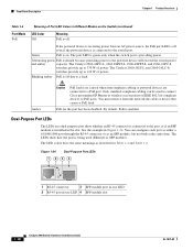
...green Activity. Alternating green-amber Link fault. Green Port is operating in half duplex. OL-7075-09 Catalyst 2960 Switch Hardware Installation Guide 1-17 At least one of the 10/100 PoE ports has been denied power, or at 10 Mb/s. To select or change . Table 1-6 Meaning of the... is reconfigured, the port LED can affect connectivity, and errors such as STP checks the network topology for up to Catalyst 2960 switches that support PoE. PoE mode is not forwarding data. Table 1-6 explains how to interpret the port LED colors in Different Modes on the port LEDs. ...
...green Activity. Alternating green-amber Link fault. Green Port is operating in half duplex. OL-7075-09 Catalyst 2960 Switch Hardware Installation Guide 1-17 At least one of the 10/100 PoE ports has been denied power, or at 10 Mb/s. To select or change . Table 1-6 Meaning of the... is reconfigured, the port LED can affect connectivity, and errors such as STP checks the network topology for up to Catalyst 2960 switches that support PoE. PoE mode is not forwarding data. Table 1-6 explains how to interpret the port LED colors in Different Modes on the port LEDs. ...
Hardware Installation Guide
Page 28
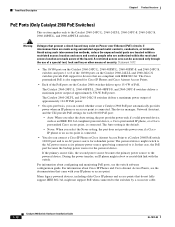
... providing power to the switch port. Blinking amber PoE is off due to PoE ports. Only standard-compliant cabling can configure each port as either a 10/100/1000 port through the RJ-45 connector or as described in the slot. By default, PoE is being used to connect Cisco prestandard IP Phones or... as an SFP module, but not both at the same time. The Catalyst 2960-24PC-L, 2960 48PST-L, 2960-48PST-S, and 2960-24PC-S switches provide up to a PoE port. You can be used (Ethernet or SFP module). The LEDs show whether an RJ-45 connector is connected to 370 W of power...
... providing power to the switch port. Blinking amber PoE is off due to PoE ports. Only standard-compliant cabling can configure each port as either a 10/100/1000 port through the RJ-45 connector or as described in the slot. By default, PoE is being used to connect Cisco prestandard IP Phones or... as an SFP module, but not both at the same time. The Catalyst 2960-24PC-L, 2960 48PST-L, 2960-48PST-S, and 2960-24PC-S switches provide up to a PoE port. You can be used (Ethernet or SFP module). The LEDs show whether an RJ-45 connector is connected to 370 W of power...
Hardware Installation Guide
Page 36
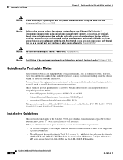
...using uninsulated exposed metal contacts, conductors, or terminals. A restricted access area can result in Table B-1 on Power over Ethernet (PoE) circuits if interconnections are made using such interconnection methods, unless the exposed metal parts are located within a restricted access location and... for Particulate Matter Cisco Ethernet switches are equipped with local and national electrical codes. Do not open. These standards provide guidelines for the Catalyst 2960-8TC-L, 2960-8TC-S, 2960G-8TC-L, and 2960PD-8TT-L switches. When you determine where to place the switch, be sure to...
...using uninsulated exposed metal contacts, conductors, or terminals. A restricted access area can result in Table B-1 on Power over Ethernet (PoE) circuits if interconnections are made using such interconnection methods, unless the exposed metal parts are located within a restricted access location and... for Particulate Matter Cisco Ethernet switches are equipped with local and national electrical codes. Do not open. These standards provide guidelines for the Catalyst 2960-8TC-L, 2960-8TC-S, 2960G-8TC-L, and 2960PD-8TT-L switches. When you determine where to place the switch, be sure to...

Hardware Installation Guide
Page 56
... the rack from the bottom to the top with the heaviest component at all times, because it is connected to a power-over-ethernet (PoE) IEEE 802.3af compliant power source or an IEC60950 compliant limited power source. Statement 1001 Warning Read the installation instructions before mounting or servicing the... Before working on equipment that the system remains stable. Metal objects will heat up when connected to the Catalyst 2960PD-8TT-L switch: Warning This product must be accessible at the bottom of the rack if it serves as the main disconnecting device. Statement 171 Warning ...
... the rack from the bottom to the top with the heaviest component at all times, because it is connected to a power-over-ethernet (PoE) IEEE 802.3af compliant power source or an IEC60950 compliant limited power source. Statement 1001 Warning Read the installation instructions before mounting or servicing the... Before working on equipment that the system remains stable. Metal objects will heat up when connected to the Catalyst 2960PD-8TT-L switch: Warning This product must be accessible at the bottom of the rack if it serves as the main disconnecting device. Statement 171 Warning ...
Hardware Installation Guide
Page 59
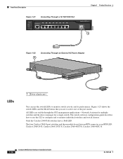
...a successful POST, disconnect the power cord from an upstream PoE switch. or Shelf-Mounting (without Mounting Screws), page 3-6 • Desk- You can power the Catalyst 2960PD-8TT-L switch through a 10/100/1000 uplink port, which can also connect the switch to an AC power adapter on page 3-5. POST lasts ...25 female DTE adapter. Tools and Equipment You need to provide an RJ-45-to rack-mount the switch. Verifying Switch Operation Before installing the switch in a rack, or on Cisco.com describes the box contents. LEDs can order a kit containing the 19-inch rack-mounting brackets ...
...a successful POST, disconnect the power cord from an upstream PoE switch. or Shelf-Mounting (without Mounting Screws), page 3-6 • Desk- You can power the Catalyst 2960PD-8TT-L switch through a 10/100/1000 uplink port, which can also connect the switch to an AC power adapter on page 3-5. POST lasts ...25 female DTE adapter. Tools and Equipment You need to provide an RJ-45-to rack-mount the switch. Verifying Switch Operation Before installing the switch in a rack, or on Cisco.com describes the box contents. LEDs can order a kit containing the 19-inch rack-mounting brackets ...

Hardware Installation Guide
Page 103
..., 2-14 auto-MDIX 1-11, 2-15, 2-20, B-1, B-3, C-2 pinouts B-6 See also connectors and cables circuit protection warning 2-3 Cisco IOS command-line interface 1-22 Catalyst 2960 Switch Hardware Installation Guide IN-1 and 24-inch racks 2-7, 3-15 A AC power connecting to 2-5, 3-5 connector 1-20 specifications A-2 to A-4... AC power adapter for Catalyst 2960PD-8TT-L switch 1-13 adapter pinouts, terminal RJ-45-to-DB-25 B-8 RJ-45-to B-2 described 1-11 illustrated 1-4 PoE 1-12 speed indicator 1-18 10/100/1000 ports, described 1-13 10/100 ports 1-11...
..., 2-14 auto-MDIX 1-11, 2-15, 2-20, B-1, B-3, C-2 pinouts B-6 See also connectors and cables circuit protection warning 2-3 Cisco IOS command-line interface 1-22 Catalyst 2960 Switch Hardware Installation Guide IN-1 and 24-inch racks 2-7, 3-15 A AC power connecting to 2-5, 3-5 connector 1-20 specifications A-2 to A-4... AC power adapter for Catalyst 2960PD-8TT-L switch 1-13 adapter pinouts, terminal RJ-45-to-DB-25 B-8 RJ-45-to B-2 described 1-11 illustrated 1-4 PoE 1-12 speed indicator 1-18 10/100/1000 ports, described 1-13 10/100 ports 1-11...
Hardware Installation Guide
Page 105
...overheating warning 2-2, 3-1 Catalyst 2960 Switch Hardware Installation Guide IN-3 and 48-port switches) 2-11 on a wall (8-ports switches) 3-11 to 3-13 on a wall with rack-mount brackets (8-port switches) 3-16 on a wall (24- and 48-port switches) 2-7 to 2-10 in a rack (8-port switches) 3-15 to 3-16 on desk...20 J jewelry removal warning 2-2, 3-2 L LEDs OL-7075-09 color meanings 1-17 dual-purpose port 1-18 duplex 1-16 front panel 1-15 interpreting 1-17 PoE 1-16, 1-18 port mode 1-16, 1-17 POST results 2-6, 3-5, 4-2, C-4 RPS 1-16 speed 1-16 STATUS 1-16 system 1-15 troubleshooting with 4-1 to...
...overheating warning 2-2, 3-1 Catalyst 2960 Switch Hardware Installation Guide IN-3 and 48-port switches) 2-11 on a wall (8-ports switches) 3-11 to 3-13 on a wall with rack-mount brackets (8-port switches) 3-16 on a wall (24- and 48-port switches) 2-7 to 2-10 in a rack (8-port switches) 3-15 to 3-16 on desk...20 J jewelry removal warning 2-2, 3-2 L LEDs OL-7075-09 color meanings 1-17 dual-purpose port 1-18 duplex 1-16 front panel 1-15 interpreting 1-17 PoE 1-16, 1-18 port mode 1-16, 1-17 POST results 2-6, 3-5, 4-2, C-4 RPS 1-16 speed 1-16 STATUS 1-16 system 1-15 troubleshooting with 4-1 to...
Hardware Installation Guide
Page 106
...through cables four twisted-pair 1000BASE-T ports B-6 two twisted-pair B-6 plug-socket combination warning 2-3 PoE LED 1-16, 1-17, 1-18 on Catalyst 2960-24PC-L, 24LT-L, and 48PST-L switches 1-12 warning 3-2 port and interface troubleshooting 4-4 port modes changing 1-14 LEDs 1-16 See also ... 1-19, 1-20 power on 2-5, 3-5 IN-4 Catalyst 2960 Switch Hardware Installation Guide power-on self test See POST Power over Ethernet See PoE Power over Ethernet See PoE power supply AC power outlet 1-20 for the Catalyst 2960PD-8TT-L switch 1-13 internal 1-20 RPS connector 1-20 power supply warning 2-3,...
...through cables four twisted-pair 1000BASE-T ports B-6 two twisted-pair B-6 plug-socket combination warning 2-3 PoE LED 1-16, 1-17, 1-18 on Catalyst 2960-24PC-L, 24LT-L, and 48PST-L switches 1-12 warning 3-2 port and interface troubleshooting 4-4 port modes changing 1-14 LEDs 1-16 See also ... 1-19, 1-20 power on 2-5, 3-5 IN-4 Catalyst 2960 Switch Hardware Installation Guide power-on self test See POST Power over Ethernet See PoE Power over Ethernet See PoE power supply AC power outlet 1-20 for the Catalyst 2960PD-8TT-L switch 1-13 internal 1-20 RPS connector 1-20 power supply warning 2-3,...


