
Hardware Installation Guide
Page 2
..., Flip Gift Card, and One Million Acts of actual IP addresses in illustrative content is no longer complying with Cisco's installation instructions, it was probably caused by FCC regulations, and you may be limited by the Cisco equipment or one side or the other company. (1002R) Any Internet Protocol (IP) addresses used in accordance with the specifications in this document are registered...
..., Flip Gift Card, and One Million Acts of actual IP addresses in illustrative content is no longer complying with Cisco's installation instructions, it was probably caused by FCC regulations, and you may be limited by the Cisco equipment or one side or the other company. (1002R) Any Internet Protocol (IP) addresses used in accordance with the specifications in this document are registered...

Hardware Installation Guide
Page 21
... attached device supports it ) and configures itself accordingly. Pinouts for this feature, see the switch software configuration guide or the switch command reference. You can use the mdix auto interface configuration command in the CLI to enable the automatic medium-dependent interface crossover (auto-MDIX) feature. When you connect the switch to workstations, servers, routers, and Cisco IP Phones, be sure to use a twisted four-pair, Category 5 or higher cable for connections to a copper 10/100/1000 or 1000BASE-T SFP module port...
... attached device supports it ) and configures itself accordingly. Pinouts for this feature, see the switch software configuration guide or the switch command reference. You can use the mdix auto interface configuration command in the CLI to enable the automatic medium-dependent interface crossover (auto-MDIX) feature. When you connect the switch to workstations, servers, routers, and Cisco IP Phones, be sure to use a twisted four-pair, Category 5 or higher cable for connections to a copper 10/100/1000 or 1000BASE-T SFP module port...
Hardware Installation Guide
Page 22
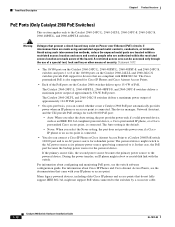
... users and service people who are authorized within the restricted access location are made aware of PoE. The Auto setting is also supported for the powered device. Many legacy powered devices, including older Cisco IP phones and access points that present a shock hazard may exist on the Catalyst 2960 switches deliver up to the switches by a crossover cable. 1-12 Catalyst 2960 Switch Hardware Installation Guide OL-7075-09 Front Panel Description Chapter 1 Product Overview PoE Ports (Only Catalyst...
... users and service people who are authorized within the restricted access location are made aware of PoE. The Auto setting is also supported for the powered device. Many legacy powered devices, including older Cisco IP phones and access points that present a shock hazard may exist on the Catalyst 2960 switches deliver up to the switches by a crossover cable. 1-12 Catalyst 2960 Switch Hardware Installation Guide OL-7075-09 Front Panel Description Chapter 1 Product Overview PoE Ports (Only Catalyst...

Hardware Installation Guide
Page 23
... and Cable Specifications." Each uplink port has two LEDs: one shows the status of the RJ-45 port, and one connector of the pair at a time. Through an external AC power adapter that first links up. Chapter 1 Product Overview Front Panel Description SFP Module Slots The Catalyst 2960 switches (other than those listed) use Gigabit Ethernet SFP modules for Gigabit uplink connections and 100-Megabit SFP modules for 100-Megabit connections to other switches. You use fiber-optic cables with...
... and Cable Specifications." Each uplink port has two LEDs: one shows the status of the RJ-45 port, and one connector of the pair at a time. Through an external AC power adapter that first links up. Chapter 1 Product Overview Front Panel Description SFP Module Slots The Catalyst 2960 switches (other than those listed) use Gigabit Ethernet SFP modules for Gigabit uplink connections and 100-Megabit SFP modules for 100-Megabit connections to other switches. You use fiber-optic cables with...

Hardware Installation Guide
Page 32
... switches, routers, access points, IP phones, and PIX firewalls. Network Assistant is available at no cost and can use the switch to create dedicated network segments that is running platforms such as CiscoWorks LAN Management Solution (LMS) and HP OpenView to the switch console port or by using Telnet from the CLI. You can manage it from anywhere in the switch software. You also can access the CLI either by connecting your network through Gigabit Ethernet connections. 1-22 Catalyst 2960 Switch Hardware Installation Guide...
... switches, routers, access points, IP phones, and PIX firewalls. Network Assistant is available at no cost and can use the switch to create dedicated network segments that is running platforms such as CiscoWorks LAN Management Solution (LMS) and HP OpenView to the switch console port or by using Telnet from the CLI. You can manage it from anywhere in the switch software. You also can access the CLI either by connecting your network through Gigabit Ethernet connections. 1-22 Catalyst 2960 Switch Hardware Installation Guide...

Hardware Installation Guide
Page 34
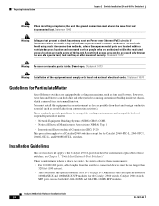
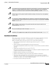
Preparing for the Catalyst 2960 Switch guide. Statement 48 Warning Ethernet cables must be shielded when used in the Regulatory Compliance and Safety Information for Installation Chapter 2 Switch Installation (24- Statement 370 Warning Read the wall-mounting instructions carefully before connecting the system to the power source. and 48-Port Switches) Warnings These warnings are translated into several languages in a central office environment. Statement 43 Warning...
Preparing for the Catalyst 2960 Switch guide. Statement 48 Warning Ethernet cables must be shielded when used in the Regulatory Compliance and Safety Information for Installation Chapter 2 Switch Installation (24- Statement 370 Warning Read the wall-mounting instructions carefully before connecting the system to the power source. and 48-Port Switches) Warnings These warnings are translated into several languages in a central office environment. Statement 43 Warning...
Hardware Installation Guide
Page 36
... 1072 Warning No user-serviceable parts inside the chassis, which lists the cable specifications for 1000BASE-X and 100BASE-X SFP modules for the Catalyst 2960 switch. These standards provide guidelines for the Catalyst 2960-8TC-L, 2960-8TC-S, 2960G-8TC-L, and 2960PD-8TT-L switches. A restricted access area can result in a system malfunction. Statement 1073 Warning Installation of security. You must be accessed only through the use both GLC-GE-100XX...
... 1072 Warning No user-serviceable parts inside the chassis, which lists the cable specifications for 1000BASE-X and 100BASE-X SFP modules for the Catalyst 2960 switch. These standards provide guidelines for the Catalyst 2960-8TC-L, 2960-8TC-S, 2960G-8TC-L, and 2960PD-8TT-L switches. A restricted access area can result in a system malfunction. Statement 1073 Warning Installation of security. You must be accessed only through the use both GLC-GE-100XX...

Hardware Installation Guide
Page 38
... time and then reflects the switch operating status. however, the instructions apply to ensure that the switch functions properly. The System LED blinks green, and the other LEDs turn green. Install the switch in a rack, on a wall, on a table, or on a shelf as described in a rack, you must take special precautions to all switches except the Catalyst 8-port switches. Statement 1006 Catalyst 2960 Switch Hardware Installation Guide 2-6 OL-7075-09 After a successful POST, disconnect the power...
... time and then reflects the switch operating status. however, the instructions apply to ensure that the switch functions properly. The System LED blinks green, and the other LEDs turn green. Install the switch in a rack, on a wall, on a table, or on a shelf as described in a rack, you must take special precautions to all switches except the Catalyst 8-port switches. Statement 1006 Catalyst 2960 Switch Hardware Installation Guide 2-6 OL-7075-09 After a successful POST, disconnect the power...
Hardware Installation Guide
Page 45
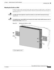
... the switch and cables, make sure the switch is not connected to a firmly attached plywood mounting backboard. Mount the switch with the front panel facing up , as shown in Figure 2-12. and 48-Port Switches) Installing the Switch Mounting the Switch on a Wall 11X 12X 11X 1X 12X 11X 1X 12X 1X 1X 11X 1X 12X MODE STASCPKEDEUDPSLTXAMTASRTPRSSYST 1 1 1 User-supplied screws 204621 OL-7075-09 Catalyst 2960 Switch Hardware Installation Guide 2-13...
... the switch and cables, make sure the switch is not connected to a firmly attached plywood mounting backboard. Mount the switch with the front panel facing up , as shown in Figure 2-12. and 48-Port Switches) Installing the Switch Mounting the Switch on a Wall 11X 12X 11X 1X 12X 11X 1X 12X 1X 1X 11X 1X 12X MODE STASCPKEDEUDPSLTXAMTASRTPRSSYST 1 1 1 User-supplied screws 204621 OL-7075-09 Catalyst 2960 Switch Hardware Installation Guide 2-13...

Hardware Installation Guide
Page 47
... enabled by default. You can take up to 30 seconds, and then the port LED turns green. The auto-MDIX feature is amber while Spanning Tree Protocol (STP) discovers the topology and searches for this feature, see the switch software configuration guide or the switch command reference. The port LED turns on , or there might not be of the same type as the SFP module on page B-4 for cable OL-7075-09 Catalyst 2960 Switch Hardware Installation Guide...
... enabled by default. You can take up to 30 seconds, and then the port LED turns green. The auto-MDIX feature is amber while Spanning Tree Protocol (STP) discovers the topology and searches for this feature, see the switch software configuration guide or the switch command reference. The port LED turns on , or there might not be of the same type as the SFP module on page B-4 for cable OL-7075-09 Catalyst 2960 Switch Hardware Installation Guide...
Hardware Installation Guide
Page 48
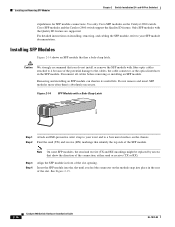
... Catalyst 2960 Switch Hardware Installation Guide OL-7075-09 For detailed instructions on the Catalyst 2960 switch. Do not remove and insert SFP modules more often than is absolutely necessary. Cisco SFP modules and the Catalyst 2960 switch support the Quality ID feature. Installing SFP Modules Figure 2-14 shows an SFP module that show the direction of the slot. Use only Cisco SFP modules on installing, removing, and cabling the SFP module, refer to the cables, the cable connector, or the optical interfaces in the SFP module...
... Catalyst 2960 Switch Hardware Installation Guide OL-7075-09 For detailed instructions on the Catalyst 2960 switch. Do not remove and insert SFP modules more often than is absolutely necessary. Cisco SFP modules and the Catalyst 2960 switch support the Quality ID feature. Installing SFP Modules Figure 2-14 shows an SFP module that show the direction of the slot. Use only Cisco SFP modules on installing, removing, and cabling the SFP module, refer to the cables, the cable connector, or the optical interfaces in the SFP module...
Hardware Installation Guide
Page 57
... Warning When installing or replacing the unit, the ground connection must always be grounded. Statement 1046 Warning No user-serviceable parts inside. and 48-Port Switches)." Contact the appropriate electrical inspection authority or an electrician if you are uncertain that suitable grounding is installed, the following ports must be connected through the vents must be handled according to the Catalyst 2960 8-port switches. When...
... Warning When installing or replacing the unit, the ground connection must always be grounded. Statement 1046 Warning No user-serviceable parts inside. and 48-Port Switches)." Contact the appropriate electrical inspection authority or an electrician if you are uncertain that suitable grounding is installed, the following ports must be connected through the vents must be handled according to the Catalyst 2960 8-port switches. When...
Hardware Installation Guide
Page 73
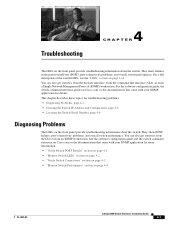
... failures, port-connectivity problems, and overall switch performance. For a full description of the switch LEDs, see the "LEDs" section on the front panel provide troubleshooting information about the switch. You can also get statistics from the browser interface, from the command-line interface (CLI), or from an SNMP workstation. You can also get statistics from the CLI or from a Simple Network Management Protocol (SNMP) workstation. See the software configuration guide, the switch command reference guide on Cisco.com, or the documentation that...
... failures, port-connectivity problems, and overall switch performance. For a full description of the switch LEDs, see the "LEDs" section on the front panel provide troubleshooting information about the switch. You can also get statistics from the browser interface, from the command-line interface (CLI), or from an SNMP workstation. You can also get statistics from the CLI or from a Simple Network Management Protocol (SNMP) workstation. See the software configuration guide, the switch command reference guide on Cisco.com, or the documentation that...

Hardware Installation Guide
Page 75
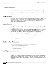
... and port type. If the link light for the switch. A link LED does not guarantee that this module supports this platform. Verify that the cable is fully functional. OL-7075-09 Catalyst 2960 Switch Hardware Installation Guide 4-3 Enable auto-MDIX on the connected device match and that they use Category 3 copper cable for 10 Mb/s unshielded twisted pair (UTP) connections. This encoding provides a way for Cisco to verify the port or module error-disabled, disabled, or shutdown status. The cable...
... and port type. If the link light for the switch. A link LED does not guarantee that this module supports this platform. Verify that the cable is fully functional. OL-7075-09 Catalyst 2960 Switch Hardware Installation Guide 4-3 Enable auto-MDIX on the connected device match and that they use Category 3 copper cable for 10 Mb/s unshielded twisted pair (UTP) connections. This encoding provides a way for Cisco to verify the port or module error-disabled, disabled, or shutdown status. The cable...
Hardware Installation Guide
Page 76
... the directly connected switch, and then work your way back port by port, interface by interface, trunk by first pinging it from the neighbor. Monitor Switch Performance Review these sections when you find unidirectional link problems. UDLD supports a normal mode of the connection. Ping the End Device Verify the end device connection by trunk, until you manually set the speed and duplex or because of port connectivity failure is a disabled port. This occurs when the traffic that the switch sends...
... the directly connected switch, and then work your way back port by port, interface by interface, trunk by first pinging it from the neighbor. Monitor Switch Performance Review these sections when you find unidirectional link problems. UDLD supports a normal mode of the connection. Ping the End Device Verify the end device connection by trunk, until you manually set the speed and duplex or because of port connectivity failure is a disabled port. This occurs when the traffic that the switch sends...
Hardware Installation Guide
Page 77
... configured, the LEDs above the mode button turn green. By default, the switch ports and interfaces are set both ends of these steps to return your NIC card might be set to autonegotiate, yet sometimes autonegotiation issues occur. The LEDs stop blinking after about 2 seconds. Upgrade the NIC card driver to the latest version available from the switch to autonegotiate. OL-7075-09 Catalyst 2960 Switch Hardware Installation Guide 4-5 To troubleshoot autonegotiation problems, try to manually set to the connected device...
... configured, the LEDs above the mode button turn green. By default, the switch ports and interfaces are set both ends of these steps to return your NIC card might be set to autonegotiate, yet sometimes autonegotiation issues occur. The LEDs stop blinking after about 2 seconds. Upgrade the NIC card driver to the latest version available from the switch to autonegotiate. OL-7075-09 Catalyst 2960 Switch Hardware Installation Guide 4-5 To troubleshoot autonegotiation problems, try to manually set to the connected device...
Hardware Installation Guide
Page 95
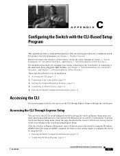
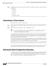
... Setup You can access the CLI through Express Setup or through the console port. Enter the setup user EXEC command. For installation procedures for mounting your PC or workstation. Connecting to a Power Source, page C-4 5. and 48-Port Switches)," and Chapter 3, "Switch Installation (8-Port Switches)." Connecting to the Console Port, page C-3 3. To put the switch into Express Setup mode, follow the steps described in the Catalyst 2960 Switch Getting Started Guide for a standalone switch. These steps describe how to configure the switch by using the CLI...
... Setup You can access the CLI through Express Setup or through the console port. Enter the setup user EXEC command. For installation procedures for mounting your PC or workstation. Connecting to a Power Source, page C-4 5. and 48-Port Switches)," and Chapter 3, "Switch Installation (8-Port Switches)." Connecting to the Console Port, page C-3 3. To put the switch into Express Setup mode, follow the steps described in the Catalyst 2960 Switch Getting Started Guide for a standalone switch. These steps describe how to configure the switch by using the CLI...
Hardware Installation Guide
Page 98
... Speed LEDs turn off and then reflect the switch operating status. As the switch powers on, it begins the power-on a switch rear panel. If a switch fails POST, the System LED turns amber. If you started the terminal emulation program before you plan to use the Network Assistant to configure and manage the switch. The RPS LED remains green for the switch to communicate with your switch fails POST. Call Cisco technical support representative if your RPS. Catalyst 2960 Switch Hardware Installation Guide...
... Speed LEDs turn off and then reflect the switch operating status. As the switch powers on, it begins the power-on a switch rear panel. If a switch fails POST, the System LED turns amber. If you started the terminal emulation program before you plan to use the Network Assistant to configure and manage the switch. The RPS LED remains green for the switch to communicate with your switch fails POST. Call Cisco technical support representative if your RPS. Catalyst 2960 Switch Hardware Installation Guide...

Hardware Installation Guide
Page 104
... B-3 SFP module ports B-3 console port connecting to C-3 described 1-21 specifications B-4 to B-8 crossover cable B-7 crossover cable, connecting to 1000BASE-T SFP module ports 2-19 crossover cable pinout, four twisted-pair, 1000BASE-T ports B-7 D DC power RPS 1-3 IN-2 Catalyst 2960 Switch Hardware Installation Guide descriptions of switch models 1-1 desk-mounting 2-14, 3-6 device manager described 1-22 to 1-17 SFP module ports 1-13 OL-7075-09 and 48-port switches 2-2 8-port switches 3-2 Ethernet ports warning 3-3 examples, network configuration 1-1 Express Setup, accessing CLI by using...
... B-3 SFP module ports B-3 console port connecting to C-3 described 1-21 specifications B-4 to B-8 crossover cable B-7 crossover cable, connecting to 1000BASE-T SFP module ports 2-19 crossover cable pinout, four twisted-pair, 1000BASE-T ports B-7 D DC power RPS 1-3 IN-2 Catalyst 2960 Switch Hardware Installation Guide descriptions of switch models 1-1 desk-mounting 2-14, 3-6 device manager described 1-22 to 1-17 SFP module ports 1-13 OL-7075-09 and 48-port switches 2-2 8-port switches 3-2 Ethernet ports warning 3-3 examples, network configuration 1-1 Express Setup, accessing CLI by using...

Hardware Installation Guide
Page 107
... twisted-pair 10/100 ports B-6 SunNet Manager 1-22 switch descriptions 1-1 switch powering on 2-5, 3-5 system LED 1-15 T technical specifications A-1 telco racks 2-7, 3-15 Telnet, and accessing the CLI 1-22 temperature, operating A-1 terminal emulation software C-3 trained and qualified personnel warning 2-3 troubleshooting 4-1 to 4-6 OL-7075-09 Index bad or damaged cable 4-2 connection problems 4-2 diagnosing problems 4-1 Ethernet and fiber-optic cables 4-3 link status 4-3 ping end device 4-4 port and interface settings 4-4 POST 4-1 spanning tree loops 4-4 speed, duplex, and autonegotiation...
... twisted-pair 10/100 ports B-6 SunNet Manager 1-22 switch descriptions 1-1 switch powering on 2-5, 3-5 system LED 1-15 T technical specifications A-1 telco racks 2-7, 3-15 Telnet, and accessing the CLI 1-22 temperature, operating A-1 terminal emulation software C-3 trained and qualified personnel warning 2-3 troubleshooting 4-1 to 4-6 OL-7075-09 Index bad or damaged cable 4-2 connection problems 4-2 diagnosing problems 4-1 Ethernet and fiber-optic cables 4-3 link status 4-3 ping end device 4-4 port and interface settings 4-4 POST 4-1 spanning tree loops 4-4 speed, duplex, and autonegotiation...


