
Hardware Installation Guide
Page 14
... Catalyst 2960-24-S Switch Front Panel Catalyst 2960 Series SI 204632 1 1 10/100 ports The 10/100 ports on the Catalyst 2960-24TC-S and Catalyst 2960-48TC-S switches are numbered as the Catalyst 2960-24T-S switch. These switches have dual-purpose ports, that port, but not Catalyst 2960 Switch Hardware Installation Guide 1-4 OL-7075-09 See Figure 1-1. and 48-port switches: • Catalyst 2960-24-S, 2960...
... Catalyst 2960-24-S Switch Front Panel Catalyst 2960 Series SI 204632 1 1 10/100 ports The 10/100 ports on the Catalyst 2960-24TC-S and Catalyst 2960-48TC-S switches are numbered as the Catalyst 2960-24T-S switch. These switches have dual-purpose ports, that port, but not Catalyst 2960 Switch Hardware Installation Guide 1-4 OL-7075-09 See Figure 1-1. and 48-port switches: • Catalyst 2960-24-S, 2960...

Hardware Installation Guide
Page 15
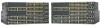
...connector type for these ports. The See Figure 1-4. Figure 1-4 Catalyst 2960-48TT-S Switch Front Panel Catalyst 2960 Series SI 271431 1 2 1 10/100 ports 2 10/100/1000 ports OL-7075-09 Catalyst 2960 Switch Hardware Installation Guide 1-5 Chapter 1 Product Overview Front Panel ...two 10/100/1000 uplink ports, numbered 1 and 2. Figure 1-2 SYST STAT DUPLX SPEED MODE Catalyst 2960-24TC-S Switch Front Panel Catalyst 2960 Series SI 204631 1 2 1 10/100 ports 2 Dual-purpose ports Figure 1-3 Catalyst 2960-48TC-S Switch Front Panel SYST STAT DUPLX SPEED MODE 1 2 3 4 5 6 7 ...
...connector type for these ports. The See Figure 1-4. Figure 1-4 Catalyst 2960-48TT-S Switch Front Panel Catalyst 2960 Series SI 271431 1 2 1 10/100 ports 2 10/100/1000 ports OL-7075-09 Catalyst 2960 Switch Hardware Installation Guide 1-5 Chapter 1 Product Overview Front Panel ...two 10/100/1000 uplink ports, numbered 1 and 2. Figure 1-2 SYST STAT DUPLX SPEED MODE Catalyst 2960-24TC-S Switch Front Panel Catalyst 2960 Series SI 204631 1 2 1 10/100 ports 2 Dual-purpose ports Figure 1-3 Catalyst 2960-48TC-S Switch Front Panel SYST STAT DUPLX SPEED MODE 1 2 3 4 5 6 7 ...

Hardware Installation Guide
Page 16
... Overview Catalyst 2960-24PC-L, 2960-24PC-S, 2960-24LC-S, 2960-24TC-L, 2960-48TC-L, 2960-24LT-L, 2960-24TT-L, 2960-48TT-L, 2960-48PST-L, and 2960-48PST-S Switches The 10/100 ports on . Figure 1-5 SYST RPS STAT DUPLX SPEED PoE MODE Catalyst 2960-24PC-L Switch Front Panel 1 2 1X 3 4 5 6 7 8 9 10 11 12 13 14 15 16 17 18 19 20 21 22 23 24 11X 13X 23X Catalyst 2960 Series PoE...
... Overview Catalyst 2960-24PC-L, 2960-24PC-S, 2960-24LC-S, 2960-24TC-L, 2960-48TC-L, 2960-24LT-L, 2960-24TT-L, 2960-48TT-L, 2960-48PST-L, and 2960-48PST-S Switches The 10/100 ports on . Figure 1-5 SYST RPS STAT DUPLX SPEED PoE MODE Catalyst 2960-24PC-L Switch Front Panel 1 2 1X 3 4 5 6 7 8 9 10 11 12 13 14 15 16 17 18 19 20 21 22 23 24 11X 13X 23X Catalyst 2960 Series PoE...
Hardware Installation Guide
Page 17
...STAT DUPLX SPEED MODE 1 2 1 10/100 ports 2 Dual-purpose ports Figure 1-9 Catalyst 2960-48TC-L Switch Front Panel 204608 SYST RPS STAT DUPLX SPEED MODE 1 2 1 10/100 ports 2 Dual-purpose ports The Catalyst 2960-24LT-L, Catalyst 2960-24TT-L, and Catalyst 2960-48TT-L switches have dual-purpose ports, that port, but not both. Ports 1 to... RPS STAT DUPLX SPEED PoE MODE 1 2 1X 34 5 6 7 8 9 10 11 12 13 14 15 16 17 18 19 20 21 22 23 24 Catalyst 2960 Series PoE-8 11X 13X 23X 2X POWER OVER ETHERNET 12X 14X 1 2 24X 1 2 3 1 10/100 PoE ports 3 10/100/1000 uplink ports 2 10/100...
...STAT DUPLX SPEED MODE 1 2 1 10/100 ports 2 Dual-purpose ports Figure 1-9 Catalyst 2960-48TC-L Switch Front Panel 204608 SYST RPS STAT DUPLX SPEED MODE 1 2 1 10/100 ports 2 Dual-purpose ports The Catalyst 2960-24LT-L, Catalyst 2960-24TT-L, and Catalyst 2960-48TT-L switches have dual-purpose ports, that port, but not both. Ports 1 to... RPS STAT DUPLX SPEED PoE MODE 1 2 1X 34 5 6 7 8 9 10 11 12 13 14 15 16 17 18 19 20 21 22 23 24 Catalyst 2960 Series PoE-8 11X 13X 23X 2X POWER OVER ETHERNET 12X 14X 1 2 24X 1 2 3 1 10/100 PoE ports 3 10/100/1000 uplink ports 2 10/100...

Hardware Installation Guide
Page 18
... 24 25 26 27 28 29 30 31 32 33 34 35 36 37 38 39 40 41 42 43 44 45 46 47 48 Catalyst 2960 Series PoE-48 11X 13X 23X 24X 35X 37X 47X 1 2 12X 14X 24X 26X 36X 38X 3 4 48X 1 2 205644 1 10/100 PoE ports 2 10/100/1000 uplink...-L Switch Front Panel 204609 SYST RPS STAT DUPLX SPEED MODE 1 2 1 10/100 ports 2 10/100/1000 uplink ports The Catalyst 2960-48PST-L and 2960-48PST-S switches have dual-purpose ports, meaning ports 21 to 24 or 45 to 48 on page 1-13. For more information about the dual-purpose ...
... 24 25 26 27 28 29 30 31 32 33 34 35 36 37 38 39 40 41 42 43 44 45 46 47 48 Catalyst 2960 Series PoE-48 11X 13X 23X 24X 35X 37X 47X 1 2 12X 14X 24X 26X 36X 38X 3 4 48X 1 2 205644 1 10/100 PoE ports 2 10/100/1000 uplink...-L Switch Front Panel 204609 SYST RPS STAT DUPLX SPEED MODE 1 2 1 10/100 ports 2 10/100/1000 uplink ports The Catalyst 2960-48PST-L and 2960-48PST-S switches have dual-purpose ports, meaning ports 21 to 24 or 45 to 48 on page 1-13. For more information about the dual-purpose ...

Hardware Installation Guide
Page 19
...Catalyst 2960 SERIES 46 47 48 2 1 10/100/1000 ports 2 Dual-purpose ports 204611 Catalyst 2960 8-Port Switches These sections describe the Catalyst 2960 8-port switches: • Catalyst 2960PD-8TT-L Switch, page 1-9 • Catalyst 2960-8TC-S, Catalyst 2960-8TC-L, and Catalyst 2960G-8TC -L Switches, page 1-10 Catalyst 2960PD-8TT-L Switch The Catalyst... that is connected through the rear panel. 204643 Figure 1-17 Catalyst 2960PD-8TT-L Switch Front Panel SYST STAT DPLX SPD 1x 2x 3x 4x 5x 6x 7x 8x CONSOLE MODE Catalyst 2960 Series 1 PoE INPUT 1 2 3 1 Console port 3 10/...
...Catalyst 2960 SERIES 46 47 48 2 1 10/100/1000 ports 2 Dual-purpose ports 204611 Catalyst 2960 8-Port Switches These sections describe the Catalyst 2960 8-port switches: • Catalyst 2960PD-8TT-L Switch, page 1-9 • Catalyst 2960-8TC-S, Catalyst 2960-8TC-L, and Catalyst 2960G-8TC -L Switches, page 1-10 Catalyst 2960PD-8TT-L Switch The Catalyst... that is connected through the rear panel. 204643 Figure 1-17 Catalyst 2960PD-8TT-L Switch Front Panel SYST STAT DPLX SPD 1x 2x 3x 4x 5x 6x 7x 8x CONSOLE MODE Catalyst 2960 Series 1 PoE INPUT 1 2 3 1 Console port 3 10/...

Hardware Installation Guide
Page 20
...Catalyst 2960-8TC-S, Catalyst 2960-8TC-L, and Catalyst 2960G-8TC-L switches (Figure 1-18 to Figure 1-20) are on page 1-21. Figure 1-18 Catalyst 2960-8TC-S Switch Front Panel 271432 SYST STAT DPLX SPD MOD E 1 2 1 Console port 3 Dual-purpose port 2 10/100/100 ports Catalyst 2960 Series SI 3 Figure 1-19 Catalyst 2960...-8TC-L Switch Front Panel SYST STAT DPLX SPD MODE CONSOLE 1x 2x 3x 4x 5x 6x 7x 8x Catalyst 2960 Series 1 204627 1 2 3 1 Console port 3 Dual-purpose...
...Catalyst 2960-8TC-S, Catalyst 2960-8TC-L, and Catalyst 2960G-8TC-L switches (Figure 1-18 to Figure 1-20) are on page 1-21. Figure 1-18 Catalyst 2960-8TC-S Switch Front Panel 271432 SYST STAT DPLX SPD MOD E 1 2 1 Console port 3 Dual-purpose port 2 10/100/100 ports Catalyst 2960 Series SI 3 Figure 1-19 Catalyst 2960...-8TC-L Switch Front Panel SYST STAT DPLX SPD MODE CONSOLE 1x 2x 3x 4x 5x 6x 7x 8x Catalyst 2960 Series 1 204627 1 2 3 1 Console port 3 Dual-purpose...
Hardware Installation Guide
Page 24
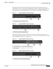
... Figure 1-21 Connecting Through a 10/100/1000 Port SYST STAT DPLX SPD 1x 2x 3x 4x 5x 6x 7x 8x CONSOLE MODE Catalyst 2960 Series 1 PoE INPUT 1 204644 Figure 1-22 1 Connecting Through an External AC Power Adapter 48V , 0.3 A 270433 LEDs 1 Power ...configure and to monitor individual switches and switch clusters. Only the Catalyst 2960 PoE switches have an RPS connector or an RPS LED: Catalyst 2960-24-S, Catalyst 2960-24TC-S, Catalyst 2960-48TT-S, Catalyst 2960-48TC-S. 1-14 Catalyst 2960 Switch Hardware Installation Guide OL-7075-09 The switch software configuration guide...
... Figure 1-21 Connecting Through a 10/100/1000 Port SYST STAT DPLX SPD 1x 2x 3x 4x 5x 6x 7x 8x CONSOLE MODE Catalyst 2960 Series 1 PoE INPUT 1 204644 Figure 1-22 1 Connecting Through an External AC Power Adapter 48V , 0.3 A 270433 LEDs 1 Power ...configure and to monitor individual switches and switch clusters. Only the Catalyst 2960 PoE switches have an RPS connector or an RPS LED: Catalyst 2960-24-S, Catalyst 2960-24TC-S, Catalyst 2960-48TT-S, Catalyst 2960-48TC-S. 1-14 Catalyst 2960 Switch Hardware Installation Guide OL-7075-09 The switch software configuration guide...

Hardware Installation Guide
Page 38
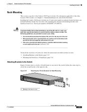
... RPS LED remains green for some time and then reflects the switch operating status. The following Cisco RPS model to the RPS receptacle: PWR-RPS2300, PWR675-AC-RPS-N1=. POST lasts approximately ... on a shelf as described in the "Installing the Switch" section on , it begins the POST, a series of the rack. • If the rack is provided with the heaviest component at the bottom of the ...a switch fails POST, the System LED turns amber. Statement 1006 Catalyst 2960 Switch Hardware Installation Guide 2-6 OL-7075-09 and 48-Port Switches) Warning Attach only the following guidelines...
... RPS LED remains green for some time and then reflects the switch operating status. The following Cisco RPS model to the RPS receptacle: PWR-RPS2300, PWR675-AC-RPS-N1=. POST lasts approximately ... on a shelf as described in the "Installing the Switch" section on , it begins the POST, a series of the rack. • If the rack is provided with the heaviest component at the bottom of the ...a switch fails POST, the System LED turns amber. Statement 1006 Catalyst 2960 Switch Hardware Installation Guide 2-6 OL-7075-09 and 48-Port Switches) Warning Attach only the following guidelines...

Hardware Installation Guide
Page 49
... wrist strap to your index finger to connect the cable. Step 3 Step 4 Insert a dust plug into the SFP module. OL-7075-09 Catalyst 2960 Switch Hardware Installation Guide 2-17 Chapter 2 Switch Installation (24- Tip For reattachment, note which cable connector plug is send (TX) and which ...open it, use . and 48-Port Switches) Installing and Removing SFP Modules Figure 2-15 Installing an SFP Module into an SFP Module Slot 1X Catalyst 2960 Series SI 11X 1 2 204639 1 1 SFP module Step 5 Remove the dust plugs from the fiber-optic cable until you cannot use your wrist ...
... wrist strap to your index finger to connect the cable. Step 3 Step 4 Insert a dust plug into the SFP module. OL-7075-09 Catalyst 2960 Switch Hardware Installation Guide 2-17 Chapter 2 Switch Installation (24- Tip For reattachment, note which cable connector plug is send (TX) and which ...open it, use . and 48-Port Switches) Installing and Removing SFP Modules Figure 2-15 Installing an SFP Module into an SFP Module Slot 1X Catalyst 2960 Series SI 11X 1 2 204639 1 1 SFP module Step 5 Remove the dust plugs from the fiber-optic cable until you cannot use your wrist ...
Hardware Installation Guide
Page 59
... with Mounting Screws), page 3-7 OL-7075-09 Catalyst 2960 Switch Hardware Installation Guide 3-5 POST lasts approximately 1 minute. The other LEDs remain solid green. Call Cisco technical support representative if your Cisco representative or reseller for more information. Chapter 3 Switch...series of the power cord to rack-mount the switch. You can power the Catalyst 2960PD-8TT-L switch through a 10/100/1000 uplink port, which can order a kit containing the 19-inch rack-mounting brackets and hardware from an upstream PoE switch. You can also connect the switch to the Catalyst 2960...
... with Mounting Screws), page 3-7 OL-7075-09 Catalyst 2960 Switch Hardware Installation Guide 3-5 POST lasts approximately 1 minute. The other LEDs remain solid green. Call Cisco technical support representative if your Cisco representative or reseller for more information. Chapter 3 Switch...series of the power cord to rack-mount the switch. You can power the Catalyst 2960PD-8TT-L switch through a 10/100/1000 uplink port, which can order a kit containing the 19-inch rack-mounting brackets and hardware from an upstream PoE switch. You can also connect the switch to the Catalyst 2960...

Hardware Installation Guide
Page 68
... is attached to the mounting magnet, do these tasks to the front-panel ports. and 48-Port Switches)." Connect to the Catalyst 2960 8-port switches. See the "Verifying Switch Operation" section on page 2-20 to a Dual-Purpose Port" section on page 3-5..../100 or 10/100/1000 port, and run Express Setup. Connect to complete the installation: 1. For information applicable to Appendix C, "Configuring the Switch with a Magnet 2 Catalyst 2960 Series 1 204636 8 x 7 x 6 x 5 x 4 x 3 x STAT DPLX SPD 1 x 2 x CONSOLE SYST 3 1 Metal surface 3 Switch 2 Magnet Step 2 Mount ...
... is attached to the mounting magnet, do these tasks to the front-panel ports. and 48-Port Switches)." Connect to the Catalyst 2960 8-port switches. See the "Verifying Switch Operation" section on page 2-20 to a Dual-Purpose Port" section on page 3-5..../100 or 10/100/1000 port, and run Express Setup. Connect to complete the installation: 1. For information applicable to Appendix C, "Configuring the Switch with a Magnet 2 Catalyst 2960 Series 1 204636 8 x 7 x 6 x 5 x 4 x 3 x STAT DPLX SPD 1 x 2 x CONSOLE SYST 3 1 Metal surface 3 Switch 2 Magnet Step 2 Mount ...
Hardware Installation Guide
Page 69
...filled rack, load the rack from Cisco. Figure 3-8 Attaching the 19-inch Brackets for Rack-Mounting SYST STAT DPLX SPD MODE CONSOLE 1x 2x 3x 4x 5x 6x 7x 8x Catalyst 2960 Series 1 1 1 Phillips flat-head screw 204637 OL-7075-09 Catalyst 2960 Switch Hardware Installation Guide 3-15 and ...Inch Rack, page 3-16 Attaching Brackets to the Switch Figure 3-8 shows how to attach a 19-inch bracket to the Catalyst 2960 8-port switches. Installing the Catalyst 2960 8-port switches in a rack, you must take special precautions to the top with the heaviest component at the bottom of ...
...filled rack, load the rack from Cisco. Figure 3-8 Attaching the 19-inch Brackets for Rack-Mounting SYST STAT DPLX SPD MODE CONSOLE 1x 2x 3x 4x 5x 6x 7x 8x Catalyst 2960 Series 1 1 1 Phillips flat-head screw 204637 OL-7075-09 Catalyst 2960 Switch Hardware Installation Guide 3-15 and ...Inch Rack, page 3-16 Attaching Brackets to the Switch Figure 3-8 shows how to attach a 19-inch bracket to the Catalyst 2960 8-port switches. Installing the Catalyst 2960 8-port switches in a rack, you must take special precautions to the top with the heaviest component at the bottom of ...
Hardware Installation Guide
Page 70
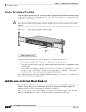
...- Figure 3-9 Mounting the Switch in a 19-Inch Rack SYST STAT DPLX SPD MODE CONSOLE 1x 2x 3x 4x 5x 6x 7x 8x 1 Catalyst 2960 Series 1 204638 1 Phillips machine screws After the switch is not included with the CLI-Based Setup Program." See the "Verifying Switch Operation" section... for instructions. 3. and 48-Port Switches)." 3-16 Catalyst 2960 Switch Hardware Installation Guide OL-7075-09 Connect to the Catalyst 2960 8-port switches. You can order a kit containing the 19-inch rack-mounting brackets and hardware from Cisco. This section is RCKMNT-19-CMPCT=. Wall-Mounting (...
...- Figure 3-9 Mounting the Switch in a 19-Inch Rack SYST STAT DPLX SPD MODE CONSOLE 1x 2x 3x 4x 5x 6x 7x 8x 1 Catalyst 2960 Series 1 204638 1 Phillips machine screws After the switch is not included with the CLI-Based Setup Program." See the "Verifying Switch Operation" section... for instructions. 3. and 48-Port Switches)." 3-16 Catalyst 2960 Switch Hardware Installation Guide OL-7075-09 Connect to the Catalyst 2960 8-port switches. You can order a kit containing the 19-inch rack-mounting brackets and hardware from Cisco. This section is RCKMNT-19-CMPCT=. Wall-Mounting (...
Hardware Installation Guide
Page 74
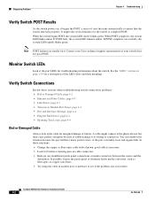
... cable might take several minutes for marginal damage or failure. Catalyst 2960 Switch Hardware Installation Guide 4-2 OL-7075-09 See the "LEDs" section on page 1-14 for broken or missing pins on , it begins the POST, a series of subtle damage to complete POST. In these sections when ...constantly loses and regains link. Monitor Switch LEDs Look at the cable for the switch to its wiring or connectors. Contact your Cisco technical support representative if your switch does not pass POST. If possible, bypass the patch panel or eliminate faulty media convertors, such...
... cable might take several minutes for marginal damage or failure. Catalyst 2960 Switch Hardware Installation Guide 4-2 OL-7075-09 See the "LEDs" section on page 1-14 for broken or missing pins on , it begins the POST, a series of subtle damage to complete POST. In these sections when ...constantly loses and regains link. Monitor Switch LEDs Look at the cable for the switch to its wiring or connectors. Contact your Cisco technical support representative if your switch does not pass POST. If possible, bypass the patch panel or eliminate faulty media convertors, such...
Hardware Installation Guide
Page 98
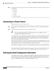
...on, it begins the power-on self test (POST), a series of tests that runs automatically to display the setup program prompt. If you started the terminal emulation program before you powered on a switch rear panel. Catalyst 2960 Switch Hardware Installation Guide C-4 OL-7075-09 The System LED ...to the power connector on your switch fails POST. The RPS LED remains green for the switch to a grounded AC outlet. Call Cisco technical support representative if your switch, the PC or terminal displays the bootloader sequence. You need to configure and manage the switch. ...
...on, it begins the power-on self test (POST), a series of tests that runs automatically to display the setup program prompt. If you started the terminal emulation program before you powered on a switch rear panel. Catalyst 2960 Switch Hardware Installation Guide C-4 OL-7075-09 The System LED ...to the power connector on your switch fails POST. The RPS LED remains green for the switch to a grounded AC outlet. Call Cisco technical support representative if your switch, the PC or terminal displays the bootloader sequence. You need to configure and manage the switch. ...

