Hardware Installation Guide
Page 3
... and Modes 1-16 Dual-Purpose Port LEDs 1-18 Cable Guard for the Catalyst 2960 8-Port Switches 1-19 Rear Panel Description 1-19 Internal Power Supply 1-20 Cisco RPS 1-20 Cisco RPS 2300 1-20 Cisco RPS 675 1-21 Console Port 1-21 Security Slots 1-21 Management Options 1-22 Network Configurations 1-22 Catalyst 2960 Switch Hardware Installation Guide iii...
... and Modes 1-16 Dual-Purpose Port LEDs 1-18 Cable Guard for the Catalyst 2960 8-Port Switches 1-19 Rear Panel Description 1-19 Internal Power Supply 1-20 Cisco RPS 1-20 Cisco RPS 2300 1-20 Cisco RPS 675 1-21 Console Port 1-21 Security Slots 1-21 Management Options 1-22 Network Configurations 1-22 Catalyst 2960 Switch Hardware Installation Guide iii...

Hardware Installation Guide
Page 13
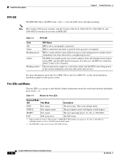
...-24TC-L, and 2960G-48TC-L switches support all the SFP modules. The Catalyst 2960-8TC-L, 2960G-8TC-L, and 2960-8TC-S switches do not have a redundant power system (RPS) connector for the RPS models. The Catalyst 2960-8TC-S, Catalyst 2960-24TC-S, and Catalyst 2960-48TC-S switches support only 1000BASE-LX/LH, 1000BASE... at 10 or 100 Mb/s in half-duplex mode when installed in Catalyst 2960 switches. For specific information about switch support for an optional Cisco RPS 2300 or Cisco RPS 675 redundant power system that operates on AC input and supplies backup DC power to the switch.
...-24TC-L, and 2960G-48TC-L switches support all the SFP modules. The Catalyst 2960-8TC-L, 2960G-8TC-L, and 2960-8TC-S switches do not have a redundant power system (RPS) connector for the RPS models. The Catalyst 2960-8TC-S, Catalyst 2960-24TC-S, and Catalyst 2960-48TC-S switches support only 1000BASE-LX/LH, 1000BASE... at 10 or 100 Mb/s in half-duplex mode when installed in Catalyst 2960 switches. For specific information about switch support for an optional Cisco RPS 2300 or Cisco RPS 675 redundant power system that operates on AC input and supplies backup DC power to the switch.
Hardware Installation Guide
Page 26
...-09 The PoE status. 1. Table 1-3 RPS LED Color Off Green Blinking green Amber Blinking amber RPS Status RPS is the default mode. Contact Cisco Systems. The internal power supply in a switch has failed, and the RPS is unavailable because it does not, the RPS fan could have an RPS LED. Note The Catalyst...
...-09 The PoE status. 1. Table 1-3 RPS LED Color Off Green Blinking green Amber Blinking amber RPS Status RPS is the default mode. Contact Cisco Systems. The internal power supply in a switch has failed, and the RPS is unavailable because it does not, the RPS fan could have an RPS LED. Note The Catalyst...
Hardware Installation Guide
Page 29
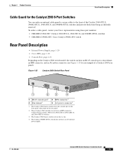
...-48TT-S switches. 3. To order a cable guard, contact your Cisco representative using these part numbers: • CBLGRD-C2960-8TC: Catalyst 2960-8TC-L, 2960-8TC-S, and 2960PD-8TT-L switches • CBLGRD-C2960G-8TC: Cisco Catalyst 2960G-8TC switch Rear Panel Description • Internal Power Supply, page 1-20 • Cisco RPS, page 1-20 • Console Port, page 1-21 Depending...
...-48TT-S switches. 3. To order a cable guard, contact your Cisco representative using these part numbers: • CBLGRD-C2960-8TC: Catalyst 2960-8TC-L, 2960-8TC-S, and 2960PD-8TT-L switches • CBLGRD-C2960G-8TC: Cisco Catalyst 2960G-8TC switch Rear Panel Description • Internal Power Supply, page 1-20 • Cisco RPS, page 1-20 • Console Port, page 1-21 Depending...
Hardware Installation Guide
Page 30
... the following Cisco RPS model to provide backup power if the switch power supply fails: • "Cisco RPS 2300" section on page 1-20 • "Cisco RPS 675" section on Cisco.com: http://www.cisco.com/en/US/products/ps7148/prod_installation_guides_list.html Cisco RPS 2300 The Cisco RPS 2300 is...PWR-RPS2300 / PWR675-AC-RPS-N1 Statement 370 Note These Catalyst 2960 switches do not have a internal power supply. For complete information about the Cisco RPS products, including compatibility matrixes listing the supported RPS for RPS support 1-20 Catalyst 2960 Switch Hardware Installation ...
... the following Cisco RPS model to provide backup power if the switch power supply fails: • "Cisco RPS 2300" section on page 1-20 • "Cisco RPS 675" section on Cisco.com: http://www.cisco.com/en/US/products/ps7148/prod_installation_guides_list.html Cisco RPS 2300 The Cisco RPS 2300 is...PWR-RPS2300 / PWR675-AC-RPS-N1 Statement 370 Note These Catalyst 2960 switches do not have a internal power supply. For complete information about the Cisco RPS products, including compatibility matrixes listing the supported RPS for RPS support 1-20 Catalyst 2960 Switch Hardware Installation ...
Hardware Installation Guide
Page 31
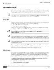
...can connect the switch to a PC by the RPS • Obtain status reports for the RPS power-supply module • Read and monitor backup, failure, and exception history Cisco RPS 675 The Cisco 675 RPS is used to secure a laptop computer, to secure either or both sides of the ...switch. Chapter 1 Product Overview Rear Panel Description • List the connected switches and the power-supply module sizes • Obtain reports when...
...can connect the switch to a PC by the RPS • Obtain status reports for the RPS power-supply module • Read and monitor backup, failure, and exception history Cisco RPS 675 The Cisco 675 RPS is used to secure a laptop computer, to secure either or both sides of the ...switch. Chapter 1 Product Overview Rear Panel Description • List the connected switches and the power-supply module sizes • Obtain reports when...
Hardware Installation Guide
Page 35
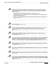
... rack from the bottom to install, replace, or service this unit in restricted access areas. Statement 1024 Warning This unit might have more than one power supply connection. Statement 1030 Warning Ultimate disposal of this product should be connected through the use of a special tool, lock and key, or other means of...
... rack from the bottom to install, replace, or service this unit in restricted access areas. Statement 1024 Warning This unit might have more than one power supply connection. Statement 1030 Warning Ultimate disposal of this product should be connected through the use of a special tool, lock and key, or other means of...
Hardware Installation Guide
Page 37
...176;C). If any item is sufficient for more information. The rear-panel power connector is within the ranges listed in the link to rack-mount the switch. Note When you might need to supply a number-2 Phillips screwdriver to avoid overloading the receiver. Tools and ... Guide 2-5 See Chapter 3, "Switch Installation (8-Port Switches)," and see the Cisco RPS documentation for unrestricted cabling. - and 48-Port Switches) Verifying Switch Operation When you use shorter lengths of an AC power receptacle. • Cabling is less than 15.43 miles (25 km), you...
...176;C). If any item is sufficient for more information. The rear-panel power connector is within the ranges listed in the link to rack-mount the switch. Note When you might need to supply a number-2 Phillips screwdriver to avoid overloading the receiver. Tools and ... Guide 2-5 See Chapter 3, "Switch Installation (8-Port Switches)," and see the Cisco RPS documentation for unrestricted cabling. - and 48-Port Switches) Verifying Switch Operation When you use shorter lengths of an AC power receptacle. • Cabling is less than 15.43 miles (25 km), you...
Hardware Installation Guide
Page 42
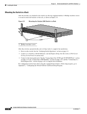
...front-panel ports. and 48-Port Switches) Mounting the Switch in a Rack After the brackets are attached to the switch, use the four supplied number-12 Phillips machine screws to securely attach the brackets to the rack, as shown in the rack, do these tasks to complete the ...installation: • Power on page 2-5. • Connect to complete the installation. Installing the Switch Chapter 2 Switch Installation (24- Figure 2-8 Mounting the Catalyst 2960 Switch in a...
...front-panel ports. and 48-Port Switches) Mounting the Switch in a Rack After the brackets are attached to the switch, use the four supplied number-12 Phillips machine screws to securely attach the brackets to the rack, as shown in the rack, do these tasks to complete the ...installation: • Power on page 2-5. • Connect to complete the installation. Installing the Switch Chapter 2 Switch Installation (24- Figure 2-8 Mounting the Catalyst 2960 Switch in a...
Hardware Installation Guide
Page 45
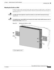
... For the best support of the switch. Warning To comply with the front panel facing up . Chapter 2 Switch Installation (24- Statement 266 Warning If a redundant power system (RPS) is attached securely to wall studs or to the switch, install an RPS connector cover on a Wall 11X 12X 11X 1X 12X 11X...
... For the best support of the switch. Warning To comply with the front panel facing up . Chapter 2 Switch Installation (24- Statement 266 Warning If a redundant power system (RPS) is attached securely to wall studs or to the switch, install an RPS connector cover on a Wall 11X 12X 11X 1X 12X 11X...
Hardware Installation Guide
Page 55
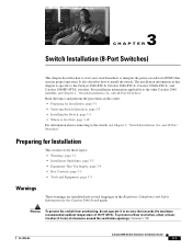
... switches. Preparing for Installation This section covers these topics: • Warnings, page 3-1 • Installation Guidelines, page 3-3 • Equipment That You Supply, page 3-4 • Box Contents, page 3-5 • Tools and Equipment, page 3-5 Warnings These warnings are translated into several languages in this order...3 C H A P T E R Switch Installation (8-Port Switches) This chapter describes how to start your switch and how to interpret the power-on self-test (POST) that exceeds the maximum recommended ambient temperature of clearance around the ventilation openings.
... switches. Preparing for Installation This section covers these topics: • Warnings, page 3-1 • Installation Guidelines, page 3-3 • Equipment That You Supply, page 3-4 • Box Contents, page 3-5 • Tools and Equipment, page 3-5 Warnings These warnings are translated into several languages in this order...3 C H A P T E R Switch Installation (8-Port Switches) This chapter describes how to start your switch and how to interpret the power-on self-test (POST) that exceeds the maximum recommended ambient temperature of clearance around the ventilation openings.
Hardware Installation Guide
Page 58
...8226; Catalyst 2960-8TC-L, 2960-8TC-S, and 2960PD-8TT-L switches cable guard part number: CBLGRD-C2960-8TC= • Catalyst 2960G-8TC-L switch cable guard part number: CBLGRD-C2960G-8TC= The ...and Catalyst 2960G-8TC-L switches. Equipment That You Supply This section is sufficient for unrestricted cabling. - To order a cable guard, contact your Cisco representative and use these conditions - Cable locks are... side panels. For information applicable to manage a large number of the link. The AC power cord can easily read the front-panel indicators. - The switch has security slots in a...
...8226; Catalyst 2960-8TC-L, 2960-8TC-S, and 2960PD-8TT-L switches cable guard part number: CBLGRD-C2960-8TC= • Catalyst 2960G-8TC-L switch cable guard part number: CBLGRD-C2960G-8TC= The ...and Catalyst 2960G-8TC-L switches. Equipment That You Supply This section is sufficient for unrestricted cabling. - To order a cable guard, contact your Cisco representative and use these conditions - Cable locks are... side panels. For information applicable to manage a large number of the link. The AC power cord can easily read the front-panel indicators. - The switch has security slots in a...
Hardware Installation Guide
Page 59
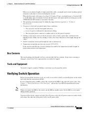
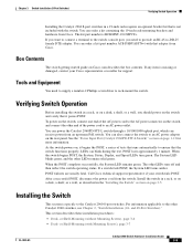
... (8-Port Switches) Verifying Switch Operation Installing the Catalyst 2960 8-port switches in a rack, or on a desk, a shelf, or a wall, you need to supply a number-2 Phillips screwdriver to rack-mount the switch. If you want to connect a terminal to the switch console port, you should... the switch. or Shelf-Mounting (with that is RCKMNT-19-CMPCT=. POST lasts approximately 1 minute. After a successful POST, disconnect the power cord from Cisco. The kit part number is not included with the switch. The System LED blinks green, and the other end of tests that runs ...
... (8-Port Switches) Verifying Switch Operation Installing the Catalyst 2960 8-port switches in a rack, or on a desk, a shelf, or a wall, you need to supply a number-2 Phillips screwdriver to rack-mount the switch. If you want to connect a terminal to the switch console port, you should... the switch. or Shelf-Mounting (with that is RCKMNT-19-CMPCT=. POST lasts approximately 1 minute. After a successful POST, disconnect the power cord from Cisco. The kit part number is not included with the switch. The System LED blinks green, and the other end of tests that runs ...
Hardware Installation Guide
Page 71
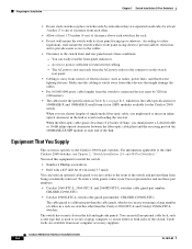
...facing up or sideways according to a firmly attached plywood mounting backboard. Figure 3-10 Mounting the Switch on a Wall 12 204634 1 Phillips flat-head screw 2 User-supplied screws After the switch is attached securely to wall studs or to safety regulations. Connect to the system. Wall-mount the switch with the front... switch. See the switch getting started guide for instructions. 3. Statement 378 Step 1 Step 2 Attach a 19-inch bracket to a Dual-Purpose Port" section on page 3-5. 2. Power on the wall, do these tasks to a 10/100 or 10/100/1000 port, and run Express Setup.
...facing up or sideways according to a firmly attached plywood mounting backboard. Figure 3-10 Mounting the Switch on a Wall 12 204634 1 Phillips flat-head screw 2 User-supplied screws After the switch is attached securely to wall studs or to safety regulations. Connect to the system. Wall-mount the switch with the front... switch. See the switch getting started guide for instructions. 3. Statement 378 Step 1 Step 2 Attach a 19-inch bracket to a Dual-Purpose Port" section on page 3-5. 2. Power on the wall, do these tasks to a 10/100 or 10/100/1000 port, and run Express Setup.
Hardware Installation Guide
Page 97
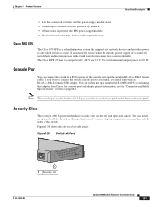
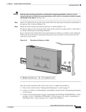
... connect the PC or terminal to the switch: Step 1 Using the supplied RJ-45-to the terminal. Step 2 Start a terminal-emulation session. Figure C-1 Connecting a Switch to a PC 1 CONSOLE 137088 3 2 1 Catalyst 2960 switch 3 RJ-45-to-DB-9 adapter cable 2 Power cord Step 2 Attach the DB-9 female DTE of a switch, as... Switch with the CLI-Based Setup Program Connecting to the Console Port Connecting to the Console Port You can see the output display from the power-on the rear of the adapter cable to a PC serial port, or attach an appropriate adapter to -DB-9 adapter cable, insert the...
... connect the PC or terminal to the switch: Step 1 Using the supplied RJ-45-to the terminal. Step 2 Start a terminal-emulation session. Figure C-1 Connecting a Switch to a PC 1 CONSOLE 137088 3 2 1 Catalyst 2960 switch 3 RJ-45-to-DB-9 adapter cable 2 Power cord Step 2 Attach the DB-9 female DTE of a switch, as... Switch with the CLI-Based Setup Program Connecting to the Console Port Connecting to the Console Port You can see the output display from the power-on the rear of the adapter cable to a PC serial port, or attach an appropriate adapter to -DB-9 adapter cable, insert the...
Hardware Installation Guide
Page 98
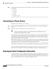
...1 stop bit • No parity • None (flow control) Connecting to a Power Source Follow these steps to connect to a power source: Step 1 Step 2 Connect one end of the supplied AC power cord to the power connector on your switch, the PC or terminal displays the bootloader sequence. The System LED...setup program prompt. POST failures are connecting the switch to a Cisco redundant power system (RPS), refer to communicate with your switch fails POST. This information is powered up. As the switch powers on, it begins the power-on self test (POST), a series of tests that shipped ...
...1 stop bit • No parity • None (flow control) Connecting to a Power Source Follow these steps to connect to a power source: Step 1 Step 2 Connect one end of the supplied AC power cord to the power connector on your switch, the PC or terminal displays the bootloader sequence. The System LED...setup program prompt. POST failures are connecting the switch to a Cisco redundant power system (RPS), refer to communicate with your switch fails POST. This information is powered up. As the switch powers on, it begins the power-on self test (POST), a series of tests that shipped ...
Hardware Installation Guide
Page 105
... under a desk 3-8 using a magnet 3-14 site requirements 2-4, 3-3 starting the terminal emulation software C-3 See also procedures installation instructions warning 2-2, 3-2 installing SFP modules 2-16 to 2-17 internal power supply 1-20 J jewelry removal warning 2-2, 3-2 L LEDs OL-7075-09 color meanings 1-17 dual-purpose port 1-18 duplex 1-16 front panel 1-15 interpreting 1-17 PoE 1-16, 1-18...
... under a desk 3-8 using a magnet 3-14 site requirements 2-4, 3-3 starting the terminal emulation software C-3 See also procedures installation instructions warning 2-2, 3-2 installing SFP modules 2-16 to 2-17 internal power supply 1-20 J jewelry removal warning 2-2, 3-2 L LEDs OL-7075-09 color meanings 1-17 dual-purpose port 1-18 duplex 1-16 front panel 1-15 interpreting 1-17 PoE 1-16, 1-18...
Hardware Installation Guide
Page 106
...results 2-6, 3-5, 4-1, C-4 running at power on 2-6, 3-5, 4-2 power connecting to 2-5, 3-5 connectors 1-19, 1-20 power on 2-5, 3-5 IN-4 Catalyst 2960 Switch Hardware Installation Guide power-on self test See POST Power over Ethernet See PoE Power over Ethernet See PoE power supply AC power outlet 1-20 for the Catalyst 2960PD-8TT... 3-15 read the wall-mounting instructions warning 2-2, 3-11, 3-17 rear panel clearance 2-5, 3-4 description 1-19 to 1-21 redundant power supply See RPS removing SFP modules 2-17 to 2-18 restricted access area warning 2-3 RJ-45 connector, console port B-4 RJ-45 console...
...results 2-6, 3-5, 4-1, C-4 running at power on 2-6, 3-5, 4-2 power connecting to 2-5, 3-5 connectors 1-19, 1-20 power on 2-5, 3-5 IN-4 Catalyst 2960 Switch Hardware Installation Guide power-on self test See POST Power over Ethernet See PoE Power over Ethernet See PoE power supply AC power outlet 1-20 for the Catalyst 2960PD-8TT... 3-15 read the wall-mounting instructions warning 2-2, 3-11, 3-17 rear panel clearance 2-5, 3-4 description 1-19 to 1-21 redundant power supply See RPS removing SFP modules 2-17 to 2-18 restricted access area warning 2-3 RJ-45 connector, console port B-4 RJ-45 console...

Hardware Installation Guide
Page 107
... tree loops 4-4 W wall-mounting 2-11, 3-16 warnings attaching the Cisco RPS 2-2, 2-6 circuit protection 2-3 class 1 laser product 2-3, 3-2 disconnecting device 2-3 Ethernet cables 2-2, 3-2 Ethernet ports 3-3 ground connection 2-4, 3-3 grounded equipment 2-3, 3-3 installation 2-2, 3-1 installation instructions 2-2, 3-2 jewelry removal 2-2, 3-2 lightning activity 2-2, 3-2 local and national electrical codes compliance 2-4, 3-3 more than one power supply 3-3 no user-serviceable parts 2-4 overheating prevention 2-2, 3-1 plug-socket combination...
... tree loops 4-4 W wall-mounting 2-11, 3-16 warnings attaching the Cisco RPS 2-2, 2-6 circuit protection 2-3 class 1 laser product 2-3, 3-2 disconnecting device 2-3 Ethernet cables 2-2, 3-2 Ethernet ports 3-3 ground connection 2-4, 3-3 grounded equipment 2-3, 3-3 installation 2-2, 3-1 installation instructions 2-2, 3-2 jewelry removal 2-2, 3-2 lightning activity 2-2, 3-2 local and national electrical codes compliance 2-4, 3-3 more than one power supply 3-3 no user-serviceable parts 2-4 overheating prevention 2-2, 3-1 plug-socket combination...


