
Hardware Installation Guide
Page 3
... Purpose vii Related Publications vii Obtaining Documentation and Submitting a Service Request viii Product Overview 1-1 Switch Models 1-1 Front Panel Description 1-3 SFP Module Slots 1-4 10/100/1000 Ethernet Ports 1-4 PoE+ Ports 1-5 Network Modules 1-5 SFP and SFP+ Modules 1-7 LEDs 1-9 System LED 1-10 XPS LED 1-11 Port LEDs and Modes 1-11 USB Console LED 1-13 S-PWR LED...
... Purpose vii Related Publications vii Obtaining Documentation and Submitting a Service Request viii Product Overview 1-1 Switch Models 1-1 Front Panel Description 1-3 SFP Module Slots 1-4 10/100/1000 Ethernet Ports 1-4 PoE+ Ports 1-5 Network Modules 1-5 SFP and SFP+ Modules 1-7 LEDs 1-9 System LED 1-10 XPS LED 1-11 Port LEDs and Modes 1-11 USB Console LED 1-13 S-PWR LED...

Hardware Installation Guide
Page 5
3 C H A P T E R 4 C H A P T E R Installing SFP and SFP+ Modules 2-24 Installing an SFP Module 2-25 Removing an SFP Module 2-26 Connecting Devices to the Ethernet Ports 2-26 10/100/1000 Ethernet Port Connections 2-27 PoE+ Port Connections 2-27 Where to... 4-1 Switch LEDs 4-1 Switch Connections 4-2 Bad or Damaged Cable 4-2 Ethernet and Fiber Cables 4-2 Link Status 4-2 10/100/1000 Port Connections 4-3 PoE Port Connections 4-3 SFP Modules 4-3 Interface Settings 4-4 Ping End Device 4-4 Spanning Tree Loops 4-4 Contents OL-19593-02 Catalyst 3750-X and 3560-X Switch Hardware Installation Guide v
3 C H A P T E R 4 C H A P T E R Installing SFP and SFP+ Modules 2-24 Installing an SFP Module 2-25 Removing an SFP Module 2-26 Connecting Devices to the Ethernet Ports 2-26 10/100/1000 Ethernet Port Connections 2-27 PoE+ Port Connections 2-27 Where to... 4-1 Switch LEDs 4-1 Switch Connections 4-2 Bad or Damaged Cable 4-2 Ethernet and Fiber Cables 4-2 Link Status 4-2 10/100/1000 Port Connections 4-3 PoE Port Connections 4-3 SFP Modules 4-3 Interface Settings 4-4 Ping End Device 4-4 Spanning Tree Loops 4-4 Contents OL-19593-02 Catalyst 3750-X and 3560-X Switch Hardware Installation Guide v

Hardware Installation Guide
Page 6
... Connector Specifications B-1 10/100/1000 Ports B-1 10 Gigabit Ethernet CX1 (SFP+ Copper) Connectors B-2 SFP and SFP+ Modules B-2 10/100 Ethernet Management Port B-3 Console Port B-4 Cable and Adapter Specifications B-5 SFP and SFP+ Module Cable Specifications B-5 Four Twisted-Pair Cable Pinouts B-7 Two Twisted-Pair... Port C-2 USB Console Port C-2 Installing the Cisco Microsoft Windows USB Device Driver C-3 Installing the Cisco Microsoft Windows XP USB Driver C-4 Installing the Cisco Microsoft Windows 2000 USB Driver C-4 Installing the Cisco Microsoft Windows Vista and Windows 7 USB Driver ...
... Connector Specifications B-1 10/100/1000 Ports B-1 10 Gigabit Ethernet CX1 (SFP+ Copper) Connectors B-2 SFP and SFP+ Modules B-2 10/100 Ethernet Management Port B-3 Console Port B-4 Cable and Adapter Specifications B-5 SFP and SFP+ Module Cable Specifications B-5 Four Twisted-Pair Cable Pinouts B-7 Two Twisted-Pair... Port C-2 USB Console Port C-2 Installing the Cisco Microsoft Windows USB Device Driver C-3 Installing the Cisco Microsoft Windows XP USB Driver C-4 Installing the Cisco Microsoft Windows 2000 USB Driver C-4 Installing the Cisco Microsoft Windows Vista and Windows 7 USB Driver ...

Hardware Installation Guide
Page 10
Catalyst 3750-X and 3560-X Switch Hardware Installation Guide x OL-19593-02 Preface Information about Cisco SFP and SFP+ modules is available from this Cisco.com site: http://www.cisco.com/en/US/products/hw/modules/ps5455/prod_installation_guides_list.html SFP compatibility matrix documents are a free service and Cisco currently supports RSS Version 2.0. The RSS feeds are available from this...
Catalyst 3750-X and 3560-X Switch Hardware Installation Guide x OL-19593-02 Preface Information about Cisco SFP and SFP+ modules is available from this Cisco.com site: http://www.cisco.com/en/US/products/hw/modules/ps5455/prod_installation_guides_list.html SFP compatibility matrix documents are a free service and Cisco currently supports RSS Version 2.0. The RSS feeds are available from this...

Hardware Installation Guide
Page 12
... Overview Table 1-1 Catalyst 3750-X Switch Models (continued) Switch Model Cisco IOS Image Catalyst 3750-X-48T-S IP Base image3 Catalyst 3750-X-24P-S IP Base image3 Catalyst 3750-X-48P-S IP Base image3 Catalyst 3750-X-48PF-S IP Base image3 Catalyst 3750-X-12S-S IP Base image3 Catalyst 3750.../100/1000 PoE+2 ports, StackWise Plus, StackPower, 1 network module1 slot, 1100-W power supply 12 SFP module slots, StackWise Plus, StackPower, 1 network module1 slot, 350-W power supply 24 SFP module slots, StackWise Plus, StackPower, 1 network module1 slot, 350-W power supply Catalyst 3750-X-12S-E...
... Overview Table 1-1 Catalyst 3750-X Switch Models (continued) Switch Model Cisco IOS Image Catalyst 3750-X-48T-S IP Base image3 Catalyst 3750-X-24P-S IP Base image3 Catalyst 3750-X-48P-S IP Base image3 Catalyst 3750-X-48PF-S IP Base image3 Catalyst 3750-X-12S-S IP Base image3 Catalyst 3750.../100/1000 PoE+2 ports, StackWise Plus, StackPower, 1 network module1 slot, 1100-W power supply 12 SFP module slots, StackWise Plus, StackPower, 1 network module1 slot, 350-W power supply 24 SFP module slots, StackWise Plus, StackPower, 1 network module1 slot, 350-W power supply Catalyst 3750-X-12S-E...

Hardware Installation Guide
Page 13
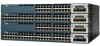
...24T-S IP Base image3 Catalyst 3560-X-48T-S IP Base image3 Catalyst 3560-X-24P-S IP Base image3 Catalyst 3560-X-48P-S IP Base image3 Catalyst 3560-X-48PF-S IP Base image3 Description 24 10/100/1000 Ethernet ports, 1 network module1 slot, 350-W power supply 48 10/100/1000 Ethernet ports, ... 19 20 21 22 23 24 C3KX-NM-1G NMEOTWDUOLREK G1 G2 G3 G4 5 1 Mode button 2 USB Type-B console port 3 Status LEDs 4 SFP module slots (downlink) 5 Network Module 282317 OL-19593-02 Catalyst 3750-X and 3560-X Switch Hardware Installation Guide 1-3 Available network modules: 10-Gigabit Ethernet network...
...24T-S IP Base image3 Catalyst 3560-X-48T-S IP Base image3 Catalyst 3560-X-24P-S IP Base image3 Catalyst 3560-X-48P-S IP Base image3 Catalyst 3560-X-48PF-S IP Base image3 Description 24 10/100/1000 Ethernet ports, 1 network module1 slot, 350-W power supply 48 10/100/1000 Ethernet ports, ... 19 20 21 22 23 24 C3KX-NM-1G NMEOTWDUOLREK G1 G2 G3 G4 5 1 Mode button 2 USB Type-B console port 3 Status LEDs 4 SFP module slots (downlink) 5 Network Module 282317 OL-19593-02 Catalyst 3750-X and 3560-X Switch Hardware Installation Guide 1-3 Available network modules: 10-Gigabit Ethernet network...

Hardware Installation Guide
Page 14
...and specifications, see the "Network Modules" section on the Catalyst 3750-X-12S and Catalyst 3750-X-24S switch support any combination of supported SFP modules. 10/100/1000 Ethernet Ports The 10/100/1000 Ethernet ports use Category 3 or Category 4 UTP cable. See Table 1-4..." section on page 2-27 and Appendix B, "Connector and Cable Specifications." The 10BASE-T traffic can use RJ-45 connectors with Ethernet pinouts. SFP+ modules are not supported. The 100BASE-TX and 1000BASE-T traffic requires Category 5, Category 5e, or Category 6 unshielded twisted pair (UTP) cable...
...and specifications, see the "Network Modules" section on the Catalyst 3750-X-12S and Catalyst 3750-X-24S switch support any combination of supported SFP modules. 10/100/1000 Ethernet Ports The 10/100/1000 Ethernet ports use Category 3 or Category 4 UTP cable. See Table 1-4..." section on page 2-27 and Appendix B, "Connector and Cable Specifications." The 10BASE-T traffic can use RJ-45 connectors with Ethernet pinouts. SFP+ modules are not supported. The 100BASE-TX and 1000BASE-T traffic requires Category 5, Category 5e, or Category 6 unshielded twisted pair (UTP) cable...

Hardware Installation Guide
Page 15
...The switch supports one hot-swappable network module that provides uplink ports to connect to other switches (only Catalyst 3750-X switches) • Configurable support for Cisco intelligent power management, including enhanced power negotiation, power reservation, and per port. You must insert the network module during switch operation. See Table 1-17... Ports" section on page 2-27, and Appendix B, "Connector and Cable Specifications." The switch generates logs when you insert or remove a network module with SFP ports. A blank module is not supported. Note The output of PoE+.
...The switch supports one hot-swappable network module that provides uplink ports to connect to other switches (only Catalyst 3750-X switches) • Configurable support for Cisco intelligent power management, including enhanced power negotiation, power reservation, and per port. You must insert the network module during switch operation. See Table 1-17... Ports" section on page 2-27, and Appendix B, "Connector and Cable Specifications." The switch generates logs when you insert or remove a network module with SFP ports. A blank module is not supported. Note The output of PoE+.

Hardware Installation Guide
Page 16
... The service module supports Net Flow and MACSec Uplink Encryption (switchto-switch encryption between uplinks). If you insert an SFP+ module in Slot 2, the SFP in Slot 2 whether it is first inserted in the Switch" section on configuring the service module, refer to ... precedence applies to the Configuring the Network Services Module note. 1-Gigabit Ethernet This module has four 1-Gigabit SFP module slots. Any combination of one SFP slot and one 10-Gigabit SFP+ module. C3KX-NM_BLNK 1. For information about the network modules, see Appendix B, "Connector and Cable Specifications...
... The service module supports Net Flow and MACSec Uplink Encryption (switchto-switch encryption between uplinks). If you insert an SFP+ module in Slot 2, the SFP in Slot 2 whether it is first inserted in the Switch" section on configuring the service module, refer to ... precedence applies to the Configuring the Network Services Module note. 1-Gigabit Ethernet This module has four 1-Gigabit SFP module slots. Any combination of one SFP slot and one 10-Gigabit SFP+ module. C3KX-NM_BLNK 1. For information about the network modules, see Appendix B, "Connector and Cable Specifications...

Hardware Installation Guide
Page 17
... Table 1-4 Supported Cisco SFP Modules Part Number GLC-GE-100FX=1,2,3 GLC-LH-SM= GLC-SX-MM= GLC-T=1, 3 GLC-ZX-SM= GLC-BX-D=1 GLC-BX-U=1 CWDM-SFP-1470= CWDM-SFP-1490= CWDM-SFP-1510= CWDM-SFP-1530= CWDM-SFP-1550= CWDM-SFP-1570= CWDM-SFP-1590= CWDM-SFP-1610= SFP-GE-S= SFP-GE-L= Description 100FX SFP on GE SFP ports for LAN switches... and 1G/2G FC CWDM 1590-nm SFP Gigabit Ethernet and 1G/2G FC CWDM 1610-nm SFP Gigabit Ethernet and 1G/2G FC 1000BASE-SX SFP module for MMF, 850 nm (DOM)4 1000BASE-LX/LH SFP module for copper connections. Use only Cisco SFP modules on the Catalyst 3750-X-12S and ...
... Table 1-4 Supported Cisco SFP Modules Part Number GLC-GE-100FX=1,2,3 GLC-LH-SM= GLC-SX-MM= GLC-T=1, 3 GLC-ZX-SM= GLC-BX-D=1 GLC-BX-U=1 CWDM-SFP-1470= CWDM-SFP-1490= CWDM-SFP-1510= CWDM-SFP-1530= CWDM-SFP-1550= CWDM-SFP-1570= CWDM-SFP-1590= CWDM-SFP-1610= SFP-GE-S= SFP-GE-L= Description 100FX SFP on GE SFP ports for LAN switches... and 1G/2G FC CWDM 1590-nm SFP Gigabit Ethernet and 1G/2G FC CWDM 1610-nm SFP Gigabit Ethernet and 1G/2G FC 1000BASE-SX SFP module for MMF, 850 nm (DOM)4 1000BASE-LX/LH SFP module for copper connections. Use only Cisco SFP modules on the Catalyst 3750-X-12S and ...

Hardware Installation Guide
Page 18
... Cisco SFP Modules (continued) Part Number DWDM-SFP-3033= DWDM-SFP-3112= DWDM-SFP-3190= DWDM-SFP-3268= DWDM-SFP-3346= DWDM-SFP-3425= DWDM-SFP-3504= DWDM-SFP-3582= DWDM-SFP-3661= DWDM-SFP-3739= DWDM-SFP-3819= DWDM-SFP-3898= DWDM-SFP-3977= DWDM-SFP-4056= DWDM-SFP-4134= DWDM-SFP-4214= DWDM-SFP-4294= DWDM-SFP-4373= DWDM-SFP-4453= DWDM-SFP-4532= DWDM-SFP-4612= DWDM-SFP-4692= DWDM-SFP-4772...
... Cisco SFP Modules (continued) Part Number DWDM-SFP-3033= DWDM-SFP-3112= DWDM-SFP-3190= DWDM-SFP-3268= DWDM-SFP-3346= DWDM-SFP-3425= DWDM-SFP-3504= DWDM-SFP-3582= DWDM-SFP-3661= DWDM-SFP-3739= DWDM-SFP-3819= DWDM-SFP-3898= DWDM-SFP-3977= DWDM-SFP-4056= DWDM-SFP-4134= DWDM-SFP-4214= DWDM-SFP-4294= DWDM-SFP-4373= DWDM-SFP-4453= DWDM-SFP-4532= DWDM-SFP-4612= DWDM-SFP-4692= DWDM-SFP-4772...

Hardware Installation Guide
Page 19
... Cable Specifications." DOM = digital optical monitoring. This cable is only used with SFP module connectors at each end. Table 1-5 Supported Cisco SFP+ Modules Part Number SFP-10G-LR= SFP-10G-SR= SFP-10G-LRM= SFP-H10GB-CU1M= SFP-H10GB-CU3M= SFP-H10GB-CU5M= Description 10 GBASE LR SFP+ transceiver module for SMF, 1350 nm, LC duplex connector 10 GBASE SR...
... Cable Specifications." DOM = digital optical monitoring. This cable is only used with SFP module connectors at each end. Table 1-5 Supported Cisco SFP+ Modules Part Number SFP-10G-LR= SFP-10G-SR= SFP-10G-LRM= SFP-H10GB-CU1M= SFP-H10GB-CU3M= SFP-H10GB-CU5M= Description 10 GBASE LR SFP+ transceiver module for SMF, 1350 nm, LC duplex connector 10 GBASE SR...

Hardware Installation Guide
Page 22
... stack master. Blinking green Activity. Link present, no activity. Alternating green-amber Link fault. The switch is not the stack master. SPEED 10/100/1000/SFP ports Off Port is operating in full duplex. Amber STACK1 Off (stack member) Blinking green Error during stack master election. Amber Port is blocked by...
... stack master. Blinking green Activity. Link present, no activity. Alternating green-amber Link fault. The switch is not the stack master. SPEED 10/100/1000/SFP ports Off Port is operating in full duplex. Amber STACK1 Off (stack member) Blinking green Error during stack master election. Amber Port is blocked by...

Hardware Installation Guide
Page 26
Link is connected to an SFP or SFP+ port. Amber Caution Link faults are caused when noncompliant cabling is off . You must remove from the network any cable or device that causes a link ... Table 1-14 Network Module LEDs Color Off Green Blinking green Blinking amber Network Module Link Status Link is on a link, no activity. Link for the SFP or SFP+ has been disabled. 1-16 Catalyst 3750-X and 3560-X Switch Hardware Installation Guide OL-19593-02 Use only standard-compliant cabling to connect to a fault...
Link is connected to an SFP or SFP+ port. Amber Caution Link faults are caused when noncompliant cabling is off . You must remove from the network any cable or device that causes a link ... Table 1-14 Network Module LEDs Color Off Green Blinking green Blinking amber Network Module Link Status Link is on a link, no activity. Link for the SFP or SFP+ has been disabled. 1-16 Catalyst 3750-X and 3560-X Switch Hardware Installation Guide OL-19593-02 Use only standard-compliant cabling to connect to a fault...

Hardware Installation Guide
Page 30
... (AC LED is available to switch active. Power output to power other devices. PS OK Off Green AC input power present. and 24-Port Switch SFP Switch Spare Spare C3KX-PWR-715WAC= Spare Primary or spare Spare Spare Spare C3KX-PWR-350WAC= Spare Spare Primary or spare Primary or spare Primary...
... (AC LED is available to switch active. Power output to power other devices. PS OK Off Green AC input power present. and 24-Port Switch SFP Switch Spare Spare C3KX-PWR-715WAC= Spare Primary or spare Spare Spare Spare C3KX-PWR-350WAC= Spare Spare Primary or spare Primary or spare Primary...

Hardware Installation Guide
Page 35
... This section includes the basic installation caution and warning statements. Read the topics and perform the procedures in the Switch, page 2-22 • Installing SFP and SFP+ Modules, page 2-24 • Connecting Devices to the Ethernet Ports, page 2-26 • Where to Go Next, page 2-29 For initial ... a Network Module in this section before you start the installation procedure. Preparing for the Catalyst 3750-X and 3560-X Switch document available at Cisco.com. It also includes planning and cabling considerations for powering information, see the switch getting started guide on...
... This section includes the basic installation caution and warning statements. Read the topics and perform the procedures in the Switch, page 2-22 • Installing SFP and SFP+ Modules, page 2-24 • Connecting Devices to the Ethernet Ports, page 2-26 • Where to Go Next, page 2-29 For initial ... a Network Module in this section before you start the installation procedure. Preparing for the Catalyst 3750-X and 3560-X Switch document available at Cisco.com. It also includes planning and cabling considerations for powering information, see the switch getting started guide on...

Hardware Installation Guide
Page 37
... Ethernet. Access to ports is sufficient for electromagnetic compatibility and safety, connect the Ethernet cables only to intrabuilding or nonexposed wiring or cabling. See the SFP or SFP+ module documentation for more information. • For switches with local and national electrical codes. OL-19593-02 Catalyst 3750-X and 3560-X Switch Hardware Installation...: • Clearance to front and rear panels is such that exit from the AC power outlet to the connector on the switch rear panel. - The SFP or SFP+ module minimum bend radius and connector length is met.
... Ethernet. Access to ports is sufficient for electromagnetic compatibility and safety, connect the Ethernet cables only to intrabuilding or nonexposed wiring or cabling. See the SFP or SFP+ module documentation for more information. • For switches with local and national electrical codes. OL-19593-02 Catalyst 3750-X and 3560-X Switch Hardware Installation...: • Clearance to front and rear panels is such that exit from the AC power outlet to the connector on the switch rear panel. - The SFP or SFP+ module minimum bend radius and connector length is met.

Hardware Installation Guide
Page 38
...as metal flakes from construction activities) as is possible. You must install this equipment in system malfunction. These standards provide guidelines for SFP+ module connections, see the "Cable and Adapter Specifications" section on page B-5. For connecting the StackWise cables, you might need to ...45°C). Planning a Switch Data Stack (Catalyst 3750-X Switches) Catalyst 3750-X switches can be greater than normal room temperature. • Cisco Ethernet Switches are equipped with the DC power supply) - If the switch is away from the switch to connected devices can share bandwidth...
...as metal flakes from construction activities) as is possible. You must install this equipment in system malfunction. These standards provide guidelines for SFP+ module connections, see the "Cable and Adapter Specifications" section on page B-5. For connecting the StackWise cables, you might need to ...45°C). Planning a Switch Data Stack (Catalyst 3750-X Switches) Catalyst 3750-X switches can be greater than normal room temperature. • Cisco Ethernet Switches are equipped with the DC power supply) - If the switch is away from the switch to connected devices can share bandwidth...

Hardware Installation Guide
Page 57
... interface configuration commands. A module interface might change to install an SFP or SFP+ module. Chapter 2 Switch Installation Installing a Network Module in the Switch Use only Cisco network modules and SFP or SFP+ modules with connected fiber-optic cables. Caution Do not insert or...module with the switch faceplate. Do not remove and insert any network module more information about supported SFP modules, see the "SFP and SFP+ Modules" section on Cisco.com. For information about installing, removing, cabling, and troubleshooting network modules, see Appendix B, "Connector and...
... interface configuration commands. A module interface might change to install an SFP or SFP+ module. Chapter 2 Switch Installation Installing a Network Module in the Switch Use only Cisco network modules and SFP or SFP+ modules with connected fiber-optic cables. Caution Do not insert or...module with the switch faceplate. Do not remove and insert any network module more information about supported SFP modules, see the "SFP and SFP+ Modules" section on Cisco.com. For information about installing, removing, cabling, and troubleshooting network modules, see Appendix B, "Connector and...

Hardware Installation Guide
Page 58
...the module that the switch supports. Use only Cisco SFP modules on the right side of SFP modules that you removed in an antistatic bag or other protective environment. Install a replacement network module or a blank module in the slot. Installing SFP and SFP+ Modules This section describes how to release it...modules before removing the network module from the slot. See the "SFP and SFP+ Modules" section on page 1-7 and the switch release notes on Cisco.com for the list of the network module to install and remove SFP modules in the switch and in the network module. Loosen the ...
...the module that the switch supports. Use only Cisco SFP modules on the right side of SFP modules that you removed in an antistatic bag or other protective environment. Install a replacement network module or a blank module in the slot. Installing SFP and SFP+ Modules This section describes how to release it...modules before removing the network module from the slot. See the "SFP and SFP+ Modules" section on page 1-7 and the switch release notes on Cisco.com for the list of the network module to install and remove SFP modules in the switch and in the network module. Loosen the ...

