
Hardware Installation Guide
Page 11
...and Adapter Pinouts B-9 Identifying a Crossover Cable B-9 Adapter Pinouts B-10 Managing the Switch by Using the Cluster Management Suite C-1 Connecting to an Ethernet Port C-2 Launching the Switch Home Page C-3 CMS Requirements C-5 Recommended Configuration for Web-Based Management C-6 Operating System and Browser Support C-6 Supported Java Plug-Ins C-7 Java Plug-In Notes C-8 Where to Go Next C-8 Quick Setup By Using the CLI-Based Setup Program D-1 Methods for Accessing the CLI D-2 Accessing the CLI Through Express Setup (Unconfigured Switch Only) D-2 Accessing the CLI Through the Console Port...
...and Adapter Pinouts B-9 Identifying a Crossover Cable B-9 Adapter Pinouts B-10 Managing the Switch by Using the Cluster Management Suite C-1 Connecting to an Ethernet Port C-2 Launching the Switch Home Page C-3 CMS Requirements C-5 Recommended Configuration for Web-Based Management C-6 Operating System and Browser Support C-6 Supported Java Plug-Ins C-7 Java Plug-In Notes C-8 Where to Go Next C-8 Quick Setup By Using the CLI-Based Setup Program D-1 Methods for Accessing the CLI D-2 Accessing the CLI Through Express Setup (Unconfigured Switch Only) D-2 Accessing the CLI Through the Console Port...

Hardware Installation Guide
Page 32
... routers and the Internet. The SYST LED turns amber if the POST fails. Catalyst 3750 Switch Hardware Installation Guide 1-4 78-15136-02 To create a username for the switch, use to the switch after Express Startup is complete, only the SYST and STAT LEDs remain green. For information about troubleshooting a POST failure, see Chapter 4, "Troubleshooting," to determine a course of the power cable to the switch. After the switch powers on, it begins the power-on self-test (POST), a series...
... routers and the Internet. The SYST LED turns amber if the POST fails. Catalyst 3750 Switch Hardware Installation Guide 1-4 78-15136-02 To create a username for the switch, use to the switch after Express Startup is complete, only the SYST and STAT LEDs remain green. For information about troubleshooting a POST failure, see Chapter 4, "Troubleshooting," to determine a course of the power cable to the switch. After the switch powers on, it begins the power-on self-test (POST), a series...

Hardware Installation Guide
Page 36
... ran before pressing the Mode button to the Ethernet port on page B-9 for copper Ethernet connections and configures the interfaces accordingly. Catalyst 3750 Switch Hardware Installation Guide 1-8 78-15136-02 Therefore, you verify that only the SYST and STAT LEDs are green before starting Express Setup? To configure the switch by default. If not, reconnect the cable to begin Express Setup. For configuration information for connections to the switch software configuration guide or the switch command reference. Note The rest of...
... ran before pressing the Mode button to the Ethernet port on page B-9 for copper Ethernet connections and configures the interfaces accordingly. Catalyst 3750 Switch Hardware Installation Guide 1-8 78-15136-02 Therefore, you verify that only the SYST and STAT LEDs are green before starting Express Setup? To configure the switch by default. If not, reconnect the cable to begin Express Setup. For configuration information for connections to the switch software configuration guide or the switch command reference. Note The rest of...

Hardware Installation Guide
Page 37
... the Default Gateway field. Note You must specify a default gateway if the management workstation and the switch are not allowed. (Optional) Enter the name of your password in the Confirm Switch Password field. This identifies the system administrator for the switch. Chapter 1 Using Express Setup Configuring the Switch Settings Configuring the Switch Settings The Management Interface field displays VLAN1-Default. Enter the IP address of the switch. 78-15136-02 Catalyst 3750 Switch Hardware Installation Guide 1-9 The password can...
... the Default Gateway field. Note You must specify a default gateway if the management workstation and the switch are not allowed. (Optional) Enter the name of your password in the Confirm Switch Password field. This identifies the system administrator for the switch. Chapter 1 Using Express Setup Configuring the Switch Settings Configuring the Switch Settings The Management Interface field displays VLAN1-Default. Enter the IP address of the switch. 78-15136-02 Catalyst 3750 Switch Hardware Installation Guide 1-9 The password can...

Hardware Installation Guide
Page 38
... production network. Enable SNMP only if you have installed the switch in the Telnet Password field. Your switch is connected the network. You can access MIB objects, but does not allow embedded spaces at the beginning or end. Verifying Switch IP Address (Optional) After you plan to verify the IP address configured on your settings. Enter a password in your network, follow these steps to manage switches by using Cisco Works or another SNMP-based network-management...
... production network. Enable SNMP only if you have installed the switch in the Telnet Password field. Your switch is connected the network. You can access MIB objects, but does not allow embedded spaces at the beginning or end. Verifying Switch IP Address (Optional) After you plan to verify the IP address configured on your settings. Enter a password in your network, follow these steps to manage switches by using Cisco Works or another SNMP-based network-management...

Hardware Installation Guide
Page 40
... Management Suite-Launch the CMS, through which you can configure and monitor a switch or switch clusters, display network topologies to gather link information, and display switch images to modify switch- and port-level settings. Other Switch Home Page Features These additional features are available from the switch home page, as Telnet and Extended Ping. • Help Resources-Access Catalyst 3750 documentation. Where to Go Next Chapter 1 Using Express Setup...
... Management Suite-Launch the CMS, through which you can configure and monitor a switch or switch clusters, display network topologies to gather link information, and display switch images to modify switch- and port-level settings. Other Switch Home Page Features These additional features are available from the switch home page, as Telnet and Extended Ping. • Help Resources-Access Catalyst 3750 documentation. Where to Go Next Chapter 1 Using Express Setup...

Hardware Installation Guide
Page 46
.... Catalyst 3750 Switch Hardware Installation Guide 2-6 78-15136-02 You can set the 10/100/1000 ports to the switch software configuration guide or the switch command reference. You can also set these ports for speed and duplex autonegotiation in compliance with IEEE 802.3ab. (The default setting is enabled, the switch detects the required cable type for the cables are described in Appendix B, "Connector and Cable Specifications." Pinouts for copper Ethernet connections and configures the interfaces accordingly. If the connected device also supports...
.... Catalyst 3750 Switch Hardware Installation Guide 2-6 78-15136-02 You can set the 10/100/1000 ports to the switch software configuration guide or the switch command reference. You can also set these ports for speed and duplex autonegotiation in compliance with IEEE 802.3ab. (The default setting is enabled, the switch detects the required cable type for the cables are described in Appendix B, "Connector and Cable Specifications." Pinouts for copper Ethernet connections and configures the interfaces accordingly. If the connected device also supports...

Hardware Installation Guide
Page 49
... device). 78-15136-02 Catalyst 3750 Switch Hardware Installation Guide 2-9 RPS is connected but is providing power to another device (redundancy has been allocated to a neighboring device). Contact Cisco Systems. The internal power supply in a fault condition. Table 2-1 lists the LED colors and their meanings. Table 2-2 RPS LED Color Off Green Flashing green Amber Flashing amber RPS Status RPS is in standby mode or in a switch has failed, and the RPS is operating normally. Table 2-1 System LED Color Off Green Amber System Status...
... device). 78-15136-02 Catalyst 3750 Switch Hardware Installation Guide 2-9 RPS is connected but is providing power to another device (redundancy has been allocated to a neighboring device). Contact Cisco Systems. The internal power supply in a fault condition. Table 2-1 lists the LED colors and their meanings. Table 2-2 RPS LED Color Off Green Flashing green Amber Flashing amber RPS Status RPS is in standby mode or in a switch has failed, and the RPS is operating normally. Table 2-1 System LED Color Off Green Amber System Status...
Hardware Installation Guide
Page 56
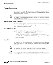
... should fail. Use the supplied RPS connector cable to connect the RPS to the same AC power source. Cisco RPS 300 The Cisco RPS 300 has two output levels: -48V and 12V with a total maximum output power of switches. Note The Cisco RPS 300 does not support the Catalyst 3750G-24TS switches. Cisco RPS Connector Specific Cisco RPS modes support specific Catalyst 3750 switches: • Cisco RPS 300 (model PWR300-AC-RPS-N1) supports the Catalyst...
... should fail. Use the supplied RPS connector cable to connect the RPS to the same AC power source. Cisco RPS 300 The Cisco RPS 300 has two output levels: -48V and 12V with a total maximum output power of switches. Note The Cisco RPS 300 does not support the Catalyst 3750G-24TS switches. Cisco RPS Connector Specific Cisco RPS modes support specific Catalyst 3750 switches: • Cisco RPS 300 (model PWR300-AC-RPS-N1) supports the Catalyst...
Hardware Installation Guide
Page 58
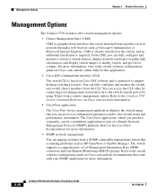
... Internet Explorer. From CMS, you can be a standalone application or part of Management Information Base (MIB) extensions and four Remote Monitoring (RMON) groups. Refer to the CiscoView documentation for this application. • Cisco IOS command-line interface (CLI) The switch CLI is based on Cisco.com for more information, refer to the switch software configuration guide on Cisco.com and the documentation that you can fully configure and monitor the switch and switch cluster members from a SNMP...
... Internet Explorer. From CMS, you can be a standalone application or part of Management Information Base (MIB) extensions and four Remote Monitoring (RMON) groups. Refer to the CiscoView documentation for this application. • Cisco IOS command-line interface (CLI) The switch CLI is based on Cisco.com for more information, refer to the switch software configuration guide on Cisco.com and the documentation that you can fully configure and monitor the switch and switch cluster members from a SNMP...

Hardware Installation Guide
Page 90
... switch software configuration guide or the switch command reference. For configuration information, refer to the front-panel ports. Installing the Switch Chapter 3 Switch Installation After the switch is mounted in the rack, you might need to perform these tasks to a Power Source" section on page 1-6. See the "Connecting to complete the installation, run the setup program, and access the switch: • (Optional) Connect the switches in the stacks. To use the CLI, enter commands at the Switch> prompt through the console port...
... switch software configuration guide or the switch command reference. For configuration information, refer to the front-panel ports. Installing the Switch Chapter 3 Switch Installation After the switch is mounted in the rack, you might need to perform these tasks to a Power Source" section on page 1-6. See the "Connecting to complete the installation, run the setup program, and access the switch: • (Optional) Connect the switches in the stacks. To use the CLI, enter commands at the Switch> prompt through the console port...

Hardware Installation Guide
Page 105
... Ethernet connections and configures the interfaces accordingly. If the port LED does not turn on the other device. For configuration information for cable-pinout descriptions.) Note When connecting to 1000BASE-T-compatible devices, be sure to switches or repeaters, use a twisted four-pair, Category 5 cable. Step 2 Connect the other end 78-15136-02 Catalyst 3750 Switch Hardware Installation Guide 3-45 Note On switches running Cisco IOS Release 12.1(14)EA1 or later, you can use the mdix auto command...
... Ethernet connections and configures the interfaces accordingly. If the port LED does not turn on the other device. For configuration information for cable-pinout descriptions.) Note When connecting to 1000BASE-T-compatible devices, be sure to switches or repeaters, use a twisted four-pair, Category 5 cable. Step 2 Connect the other end 78-15136-02 Catalyst 3750 Switch Hardware Installation Guide 3-45 Note On switches running Cisco IOS Release 12.1(14)EA1 or later, you can use the mdix auto command...
Hardware Installation Guide
Page 111
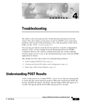
... RPS, the Master, the Status, and the Duplex LEDs turn green for 2 seconds. They show failures in the power-on page 2-8. Refer to the software configuration guide, the switch command reference guide on , it begins POST, a series of the switch LEDs, see the "LEDs" section on self-test (POST), port-connectivity problems, and overall switch performance. You can also get statistics from the browser interface, from the command-line interface (CLI), or from a Simple Network Management Protocol (SNMP) workstation. This chapter describes...
... RPS, the Master, the Status, and the Duplex LEDs turn green for 2 seconds. They show failures in the power-on page 2-8. Refer to the software configuration guide, the switch command reference guide on , it begins POST, a series of the switch LEDs, see the "LEDs" section on self-test (POST), port-connectivity problems, and overall switch performance. You can also get statistics from the browser interface, from the command-line interface (CLI), or from a Simple Network Management Protocol (SNMP) workstation. This chapter describes...

Hardware Installation Guide
Page 125
... Ethernet ports on the other devices. Figure B-1 shows the pinout. When the automatic crossover feature is disabled by default. Therefore, you can use the mdix auto command in the CLI to enable the automatic crossover feature. The automatic crossover feature is enabled, the switch detects the required cable type for copper Ethernet connections and configures the interfaces accordingly. APPENDIX B Connector and Cable Specifications This appendix describes the Catalyst 3750 switch ports and the cables and adapters...
... Ethernet ports on the other devices. Figure B-1 shows the pinout. When the automatic crossover feature is disabled by default. Therefore, you can use the mdix auto command in the CLI to enable the automatic crossover feature. The automatic crossover feature is enabled, the switch detects the required cable type for copper Ethernet connections and configures the interfaces accordingly. APPENDIX B Connector and Cable Specifications This appendix describes the Catalyst 3750 switch ports and the cables and adapters...
Hardware Installation Guide
Page 143
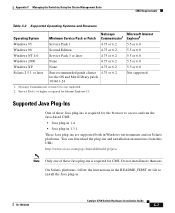
....txt file to access and run the Java-based CMS: • Java plug-in 1.4 • Java plug-in 1.3.1 These Java plug-ins are supported both in . 78-15136-02 Catalyst 3750 Switch Hardware Installation Guide C-7 Service Pack 1 or higher is required for the OS and Motif library patch 103461-24 Not supported 1. Appendix C Managing the Switch by Using the Cluster Management Suite CMS Requirements Table C-2 Supported...
....txt file to access and run the Java-based CMS: • Java plug-in 1.4 • Java plug-in 1.3.1 These Java plug-ins are supported both in . 78-15136-02 Catalyst 3750 Switch Hardware Installation Guide C-7 Service Pack 1 or higher is required for the OS and Motif library patch 103461-24 Not supported 1. Appendix C Managing the Switch by Using the Cluster Management Suite CMS Requirements Table C-2 Supported...

Hardware Installation Guide
Page 144
..., refer to the software configuration guide or to load, you are running an Internet virus checker on McAfee VirusScan, disable the VirusScan Internet Filter option, the Download Scan option, or both . From the Start menu on Windows 2000 and the plug-in takes a long time to the online help. Catalyst 3750 Switch Hardware Installation Guide C-8 78-15136-02 The Java plug-in is listed with the version number in the Control Panel menu...
..., refer to the software configuration guide or to load, you are running an Internet virus checker on McAfee VirusScan, disable the VirusScan Internet Filter option, the Download Scan option, or both . From the Start menu on Windows 2000 and the plug-in takes a long time to the online help. Catalyst 3750 Switch Hardware Installation Guide C-8 78-15136-02 The Java plug-in is listed with the version number in the Control Panel menu...

Hardware Installation Guide
Page 147
... CLI, refer to the serial port on page D-4. 78-15136-02 Catalyst 3750 Switch Hardware Installation Guide D-3 Accessing the CLI Through the Console Port You can access the CLI by connecting the console port of this release. To access the switch through a Telnet session. Appendix D Quick Setup By Using the CLI-Based Setup Program Methods for this chapter, beginning with the "Taking Out What You Need" section on your PC or workstation and access the switch through the console port...
... CLI, refer to the serial port on page D-4. 78-15136-02 Catalyst 3750 Switch Hardware Installation Guide D-3 Accessing the CLI Through the Console Port You can access the CLI by connecting the console port of this release. To access the switch through a Telnet session. Appendix D Quick Setup By Using the CLI-Based Setup Program Methods for this chapter, beginning with the "Taking Out What You Need" section on your PC or workstation and access the switch through the console port...

Hardware Installation Guide
Page 149
....R5PAaELNYMUOATLE [email protected] 90529 78-15136-02 Catalyst 3750 Switch Hardware Installation Guide D-5 Therefore, you stack your switches. When the automatic crossover feature is disabled by using the StackWise cables and ports to connect the switches. Appendix D Quick Setup By Using the CLI-Based Setup Program Stacking the Switches (Optional) Note You need to provide the Category 5 straight-through cable for this feature, refer to the switch software configuration guide or the switch command reference.
....R5PAaELNYMUOATLE [email protected] 90529 78-15136-02 Catalyst 3750 Switch Hardware Installation Guide D-5 Therefore, you stack your switches. When the automatic crossover feature is disabled by using the StackWise cables and ports to connect the switches. Appendix D Quick Setup By Using the CLI-Based Setup Program Stacking the Switches (Optional) Note You need to provide the Category 5 straight-through cable for this feature, refer to the switch software configuration guide or the switch command reference.

Hardware Installation Guide
Page 157
... Catalyst 3750 Switch Hardware Installation Guide D-13 interface FastEthernet1/0/2 interface FastEthernet1/0/3 ! ... ! interface GigabitEthernet2/0/28 ! If you want to change this configuration to nvram and exit. interface Vlan1 no shutdown ip address 10.4.120.106 255.0.0.0 ! After you complete the setup program, the switch can run the default configuration that you want to save it in nonvolatile RAM (NVRAM) by selecting option 2. If you created. Appendix D Quick Setup By Using the CLI...
... Catalyst 3750 Switch Hardware Installation Guide D-13 interface FastEthernet1/0/2 interface FastEthernet1/0/3 ! ... ! interface GigabitEthernet2/0/28 ! If you want to change this configuration to nvram and exit. interface Vlan1 no shutdown ip address 10.4.120.106 255.0.0.0 ! After you complete the setup program, the switch can run the default configuration that you want to save it in nonvolatile RAM (NVRAM) by selecting option 2. If you created. Appendix D Quick Setup By Using the CLI...
Hardware Installation Guide
Page 192
... and cables StackWise cables cable numbers 2-15 connecting to 3-37 cautions xvi chassis warning, rack-mounting and servicing E-19 Cisco IP Phones, connecting to 3-45 Cisco RPS See RPS CiscoView 2-18 CLI 2-18 accessing by using Express Setup D-2 accessing through console port D-3 Cluster Management Suite See CMS CMS 2-18 accessing your switch C-1 operating systems and supported browsers C-6 requirements C-5 to C-7 supported Java plug-ins C-7 command-line interface See CLI connecting to 10/100/1000 ports 3-44 to 10/100 ports 3-44 to console port 3-8, B-6 to SFP modules...
... and cables StackWise cables cable numbers 2-15 connecting to 3-37 cautions xvi chassis warning, rack-mounting and servicing E-19 Cisco IP Phones, connecting to 3-45 Cisco RPS See RPS CiscoView 2-18 CLI 2-18 accessing by using Express Setup D-2 accessing through console port D-3 Cluster Management Suite See CMS CMS 2-18 accessing your switch C-1 operating systems and supported browsers C-6 requirements C-5 to C-7 supported Java plug-ins C-7 command-line interface See CLI connecting to 10/100/1000 ports 3-44 to 10/100 ports 3-44 to console port 3-8, B-6 to SFP modules...


