
Hardware Installation Guide
Page 8
...or Connecting Devices to the Switch 1-12 Product Overview 2-1 Features 2-1 Front Panel Description 2-3 10/100 and 10/100/1000 Ports 2-6 SFP Module Slots 2-7 SFP Modules 2-7 LEDs 2-8 System LED 2-9 RPS LED 2-9 Master LED 2-10 Port LEDs and Modes 2-10 Rear Panel Description 2-14 StackWise ...Ports 2-15 Power Connectors 2-16 Internal Power Supply Connector 2-16 Cisco RPS Connector 2-16 Console Port 2-17 Management Options 2-18 Network Configurations 2-19 ...
...or Connecting Devices to the Switch 1-12 Product Overview 2-1 Features 2-1 Front Panel Description 2-3 10/100 and 10/100/1000 Ports 2-6 SFP Module Slots 2-7 SFP Modules 2-7 LEDs 2-8 System LED 2-9 RPS LED 2-9 Master LED 2-10 Port LEDs and Modes 2-10 Rear Panel Description 2-14 StackWise ...Ports 2-15 Power Connectors 2-16 Internal Power Supply Connector 2-16 Cisco RPS Connector 2-16 Console Port 2-17 Management Options 2-18 Network Configurations 2-19 ...

Hardware Installation Guide
Page 10
...Slots 3-43 Connecting to the 10/100 and 10/100/1000 Ports 3-44 Connecting to an SFP Module 3-46 Connecting to a Fiber-Optic SFP Module 3-47 Connecting to 1000BASE-T SFP Modules 3-48 Where to Go Next 3-50 4 C H A P T E R ...Specifications A-1 B A P P E N D I X Connector and Cable Specifications B-1 Connector Specifications B-1 10/100/1000 Ports B-1 Connecting to 1000BASE-T Devices B-2 10/100 Ports B-3 SFP Module Ports B-5 Console Port B-6 Cable and Adapter Specifications B-6 Two Twisted-Pair Cable Pinouts B-6 Four Twisted-Pair Cable Pinouts for 10/100 Ports B-7 Four Twisted-Pair...
...Slots 3-43 Connecting to the 10/100 and 10/100/1000 Ports 3-44 Connecting to an SFP Module 3-46 Connecting to a Fiber-Optic SFP Module 3-47 Connecting to 1000BASE-T SFP Modules 3-48 Where to Go Next 3-50 4 C H A P T E R ...Specifications A-1 B A P P E N D I X Connector and Cable Specifications B-1 Connector Specifications B-1 10/100/1000 Ports B-1 Connecting to 1000BASE-T Devices B-2 10/100 Ports B-3 SFP Module Ports B-5 Console Port B-6 Cable and Adapter Specifications B-6 Two Twisted-Pair Cable Pinouts B-6 Four Twisted-Pair Cable Pinouts for 10/100 Ports B-7 Four Twisted-Pair...

Hardware Installation Guide
Page 33
... 97173 1 1 Mode button Step 3 Release the Mode button. Step 4 Connect the Ethernet cable (not included) to a 10/100 Ethernet port or small form-factor pluggable (SFP) module port on page 4-2. Press and hold the Mode button, as shown in Figure 1-4, until the four LEDs above the Mode button turn green. This...
... 97173 1 1 Mode button Step 3 Release the Mode button. Step 4 Connect the Ethernet cable (not included) to a 10/100 Ethernet port or small form-factor pluggable (SFP) module port on page 4-2. Press and hold the Mode button, as shown in Figure 1-4, until the four LEDs above the Mode button turn green. This...
Hardware Installation Guide
Page 42
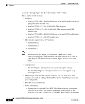
These are hot-swappable • Power redundancy - Catalyst 3750-48TS-48 10/100 Ethernet ports and 4 SFP module slots - Connection for optional Cisco RPS 300 redundant power system that operates on AC input and supplies backup DC power output to nine switches in half-duplex...-SX - 1000BASE-LX - 1000BASE-T Note When installed in Catalyst 3750 switches, 1000BASE-T small form-factor pluggable (SFP) modules can stack up to the Catalyst 3750-24TS, 3750G-24T, 3750-48TS, and 3750G-12S switches. Catalyst 3750 Switch Hardware Installation Guide 2-2 78-15136-02 Catalyst 3750-24TS-24 10/100...
These are hot-swappable • Power redundancy - Catalyst 3750-48TS-48 10/100 Ethernet ports and 4 SFP module slots - Connection for optional Cisco RPS 300 redundant power system that operates on AC input and supplies backup DC power output to nine switches in half-duplex...-SX - 1000BASE-LX - 1000BASE-T Note When installed in Catalyst 3750 switches, 1000BASE-T small form-factor pluggable (SFP) modules can stack up to the Catalyst 3750-24TS, 3750G-24T, 3750-48TS, and 3750G-12S switches. Catalyst 3750 Switch Hardware Installation Guide 2-2 78-15136-02 Catalyst 3750-24TS-24 10/100...
Hardware Installation Guide
Page 43
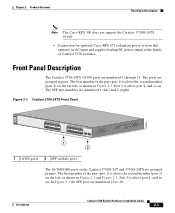
... 1) is above the second member (port 2) on the far left ) and 2 (right). The ports are grouped in Figure 2-1. Connection for optional Cisco RPS 675 redundant power system that operates on . Port 3 is above port 4, and so on AC input and supplies backup DC power output to 28... 21 22 23 24 23X 14X 24X Catalyst 3750 SERIES 1 2 1 2 1 10/100 ports 2 SFP module ports The 10/100/1000 ports on . The SFP port numbers are numbered 1 through 24. Chapter 2 Product Overview Front Panel Description Note The Cisco RPS 300 does not support the Catalyst 3750G-24TS switch. -
... 1) is above the second member (port 2) on the far left ) and 2 (right). The ports are grouped in Figure 2-1. Connection for optional Cisco RPS 675 redundant power system that operates on . Port 3 is above port 4, and so on AC input and supplies backup DC power output to 28... 21 22 23 24 23X 14X 24X Catalyst 3750 SERIES 1 2 1 2 1 10/100 ports 2 SFP module ports The 10/100/1000 ports on . The SFP port numbers are numbered 1 through 24. Chapter 2 Product Overview Front Panel Description Note The Cisco RPS 300 does not support the Catalyst 3750G-24TS switch. -
Hardware Installation Guide
Page 44
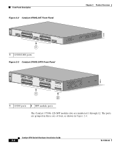
... 14 13X 15 16 17 18 19 20 21 22 23 24 23X 14X 24X Catalyst 3750 SERIES 25 26 27 28 1 2 1 10/100 ports 2 SFP module ports The Catalyst 3750G-12S SFP module slots are grouped in three sets of four, as shown in Figure 2-4.
... 14 13X 15 16 17 18 19 20 21 22 23 24 23X 14X 24X Catalyst 3750 SERIES 25 26 27 28 1 2 1 10/100 ports 2 SFP module ports The Catalyst 3750G-12S SFP module slots are grouped in three sets of four, as shown in Figure 2-4.
Hardware Installation Guide
Page 45
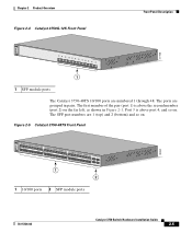
... 97166 SYST RPS MASTR STAT DUPLX SPEED STACK MODE 1 2 3 4 5 6 7 8 9 10 Catalyst 3750 SERIES 11 12 1 1 SFP module ports The Catalyst 3750-48TS 10/100 ports are grouped in Figure 2-1. Figure 2-5 Catalyst 3750-48TS Front Panel 86542 SYST RPS MASTR STAT DUPLX SPEED STACK MODE 12 1X 2X 34 56 78 9 10... 36 37 38 39 40 41 42 43 44 45 46 47 48 47X 32X 34X 48X Catalyst 3750 SERIES 1 3 2 4 1 2 1 10/100 ports 2 SFP module ports 78-15136-02 Catalyst 3750 Switch Hardware Installation Guide 2-5 The first member of the pair (port 1) is above the second member (port 2) on...
... 97166 SYST RPS MASTR STAT DUPLX SPEED STACK MODE 1 2 3 4 5 6 7 8 9 10 Catalyst 3750 SERIES 11 12 1 1 SFP module ports The Catalyst 3750-48TS 10/100 ports are grouped in Figure 2-1. Figure 2-5 Catalyst 3750-48TS Front Panel 86542 SYST RPS MASTR STAT DUPLX SPEED STACK MODE 12 1X 2X 34 56 78 9 10... 36 37 38 39 40 41 42 43 44 45 46 47 48 47X 32X 34X 48X Catalyst 3750 SERIES 1 3 2 4 1 2 1 10/100 ports 2 SFP module ports 78-15136-02 Catalyst 3750 Switch Hardware Installation Guide 2-5 The first member of the pair (port 1) is above the second member (port 2) on...

Hardware Installation Guide
Page 47
...Cisco SFP options: • 1000BASE-LX • 1000BASE-SX • 1000BASE-T For more information about these SFP modules, refer to establish fiber-optic connections. Chapter 2 Product Overview Front Panel Description SFP Module Slots The SFP module slots support the SFP modules listed in an SFP module slot. SFP... Modules The Catalyst 3750 switch uses Gigabit Ethernet SFP modules to your SFP module documentation. 78-15136-02 ...
...Cisco SFP options: • 1000BASE-LX • 1000BASE-SX • 1000BASE-T For more information about these SFP modules, refer to establish fiber-optic connections. Chapter 2 Product Overview Front Panel Description SFP Module Slots The SFP module slots support the SFP modules listed in an SFP module slot. SFP... Modules The Catalyst 3750 switch uses Gigabit Ethernet SFP modules to your SFP module documentation. 78-15136-02 ...
Hardware Installation Guide
Page 50
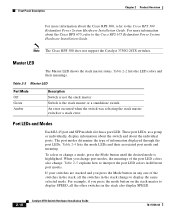
...type of the port LED colors also change port modes, the meanings of information displayed through the port LEDs. Table 2-5 explains how to the Cisco RPS 300 Redundant Power System Hardware Installation Guide. For more information about the individual ports. An error occurred when the switch was selecting the stack... any one of the switches in the stack, all the other switches in different port modes. Port LEDs and Modes Each RJ-45 port and SFP module slot has a port LED. Master LED The Master LED shows the stack master status. Switch is not the stack master. Table 2-2 lists...
...type of the port LED colors also change port modes, the meanings of information displayed through the port LEDs. Table 2-5 explains how to the Cisco RPS 300 Redundant Power System Hardware Installation Guide. For more information about the individual ports. An error occurred when the switch was selecting the stack... any one of the switches in the stack, all the other switches in different port modes. Port LEDs and Modes Each RJ-45 port and SFP module slot has a port LED. Master LED The Master LED shows the stack master status. Switch is not the stack master. Table 2-2 lists...

Hardware Installation Guide
Page 52
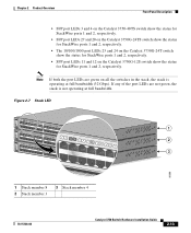
... green when the StackWise ports (on the switch rear panel) are up, and the representative stack LEDs are amber when the ports are down: • SFP port LEDs 1 and 2 on the Catalyst 3750-24TS switch show the position of a switch in a stack. The other switches in the stack. Figure 2-7 shows a ...magnified view of the LEDs on the first switch, which is operating at 100 Mbps. Green Port is member number 8 of the stack. SFP ports Off Port is operating at 1000 Mbps. STACK Off No stack member corresponding to nine switches can operate at 10, 100, or 1000 Mbps...
... green when the StackWise ports (on the switch rear panel) are up, and the representative stack LEDs are amber when the ports are down: • SFP port LEDs 1 and 2 on the Catalyst 3750-24TS switch show the position of a switch in a stack. The other switches in the stack. Figure 2-7 shows a ...magnified view of the LEDs on the first switch, which is operating at 100 Mbps. Green Port is member number 8 of the stack. SFP ports Off Port is operating at 1000 Mbps. STACK Off No stack member corresponding to nine switches can operate at 10, 100, or 1000 Mbps...
Hardware Installation Guide
Page 53
... If any of the port LEDs are green on the Catalyst 3750G-12S switch show the status for StackWise ports 1 and 2, respectively. • SFP port LEDs 11 and 12 on all the switches in the stack, the stack is not operating at full bandwidth (32 Gbps). Chapter 2 Product ...Overview Front Panel Description • SFP port LEDs 3 and 4 on the Catalyst 3750-48TS switch show the status for StackWise ports 1 and 2, respectively. • SFP port LEDs 27 and 28 on the Catalyst 3750G-24TS switch show the status for StackWise ports...
... If any of the port LEDs are green on the Catalyst 3750G-12S switch show the status for StackWise ports 1 and 2, respectively. • SFP port LEDs 11 and 12 on all the switches in the stack, the stack is not operating at full bandwidth (32 Gbps). Chapter 2 Product ...Overview Front Panel Description • SFP port LEDs 3 and 4 on the Catalyst 3750-48TS switch show the status for StackWise ports 1 and 2, respectively. • SFP port LEDs 27 and 28 on the Catalyst 3750G-24TS switch show the status for StackWise ports...

Hardware Installation Guide
Page 61
...; Connecting StackWise Cable to StackWise Ports, page 3-37 • Connecting to the 10/100 and 10/100/1000 Ports, page 3-44 • Connecting to an SFP Module, page 3-46 • Where to keep in mind while planning your switch and how to the switch. Read the topics and perform the procedures...
...; Connecting StackWise Cable to StackWise Ports, page 3-37 • Connecting to the 10/100 and 10/100/1000 Ports, page 3-44 • Connecting to an SFP Module, page 3-46 • Where to keep in mind while planning your switch and how to the switch. Read the topics and perform the procedures...

Hardware Installation Guide
Page 66
... with 62.5-micron diameter MMF, you must not exceed the stipulated cable length for 1000BASE-SX and 1000BASE-LX fiber-optic SFP connections. Front-panel indicators can cause transceiver saturation, resulting in Appendix A, "Technical Specifications." • Clearance to ports is ... • Operating environment is within the ranges listed in an elevated bit error rate (BER). Table 3-1 Fiber-Optic SFP Module Port Cabling Specifications SFP Module Wavelength (nanometers) Fiber Type Core Size (micron) Modal Bandwidth (MHz/km) Cable Distance 1000BASE-SX 850 1000BASE-...
... with 62.5-micron diameter MMF, you must not exceed the stipulated cable length for 1000BASE-SX and 1000BASE-LX fiber-optic SFP connections. Front-panel indicators can cause transceiver saturation, resulting in Appendix A, "Technical Specifications." • Clearance to ports is ... • Operating environment is within the ranges listed in an elevated bit error rate (BER). Table 3-1 Fiber-Optic SFP Module Port Cabling Specifications SFP Module Wavelength (nanometers) Fiber Type Core Size (micron) Modal Bandwidth (MHz/km) Cable Distance 1000BASE-SX 850 1000BASE-...

Hardware Installation Guide
Page 90
... to complete the installation. See the "Connecting to the 10/100 and 10/100/1000 Ports" section on page 3-44 and the "Connecting to an SFP Module" section on page 3-46 to the console port, and start the emulation software. To use CMS, go to the "Accessing the Switch from obscuring...
... to complete the installation. See the "Connecting to the 10/100 and 10/100/1000 Ports" section on page 3-44 and the "Connecting to an SFP Module" section on page 3-46 to the console port, and start the emulation software. To use CMS, go to the "Accessing the Switch from obscuring...

Hardware Installation Guide
Page 96
... an AC power source. See the "Connecting to the 10/100 and 10/100/1000 Ports" section on page 3-44 and the "Connecting to an SFP Module" section on the switch. To use CMS, go to the front-panel ports. See the "Connecting to the 10/100 and 10/100/1000... Ports" section on page 3-44 and the "Connecting to an SFP Module" section on page D-11. • Connect to the switch software configuration guide or the switch command reference. See the "Completing the Setup Program" section...
... an AC power source. See the "Connecting to the 10/100 and 10/100/1000 Ports" section on page 3-44 and the "Connecting to an SFP Module" section on the switch. To use CMS, go to the front-panel ports. See the "Connecting to the 10/100 and 10/100/1000... Ports" section on page 3-44 and the "Connecting to an SFP Module" section on page D-11. • Connect to the switch software configuration guide or the switch command reference. See the "Completing the Setup Program" section...

Hardware Installation Guide
Page 100
...cable stipulations for reliable communications. Refer to the Catalyst 3750 release notes for the list of SFP modules that the SFP module meets the requirements for Cisco to install and remove SFP modules. This encoding provides a way for the switch. 3-40 Catalyst 3750 Switch Hardware ...Cable from a StackWise Port STACK 1 STACK 2 CONSOLE 86827 Installing and Removing SFP Modules These sections describe how to identify and validate that the Catalyst 3750 switch supports. Use only Cisco SFP modules on the front of the Catalyst 3750 switches. Each port must not exceed...
...cable stipulations for reliable communications. Refer to the Catalyst 3750 release notes for the list of SFP modules that the SFP module meets the requirements for Cisco to install and remove SFP modules. This encoding provides a way for the switch. 3-40 Catalyst 3750 Switch Hardware ...Cable from a StackWise Port STACK 1 STACK 2 CONSOLE 86827 Installing and Removing SFP Modules These sections describe how to identify and validate that the Catalyst 3750 switch supports. Use only Cisco SFP modules on the front of the Catalyst 3750 switches. Each port must not exceed...
Hardware Installation Guide
Page 101
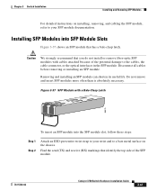
... the cables, the cable connector, or the optical interfaces in the SFP module. Do not remove and insert SFP modules more often than is absolutely necessary. Figure 3-37 SFP Module with cables attached because of the SFP module. 78-15136-02 Catalyst 3750 Switch Hardware Installation Guide 3-41 Caution...you do not install or remove fiber-optic SFP modules with a Bale-Clasp Latch 86575 To insert an SFP module into SFP Module Slots Figure 3-37 shows an SFP module that identify the top side of the potential damage to your SFP module documentation. Disconnect all cables before removing or...
... the cables, the cable connector, or the optical interfaces in the SFP module. Do not remove and insert SFP modules more often than is absolutely necessary. Figure 3-37 SFP Module with cables attached because of the SFP module. 78-15136-02 Catalyst 3750 Switch Hardware Installation Guide 3-41 Caution...you do not install or remove fiber-optic SFP modules with a Bale-Clasp Latch 86575 To insert an SFP module into SFP Module Slots Figure 3-37 shows an SFP module that identify the top side of the potential damage to your SFP module documentation. Disconnect all cables before removing or...

Hardware Installation Guide
Page 102
..., the send and receive (TX and RX) markings might be replaced by arrows that show the direction of the slot opening. Figure 3-38 Installing an SFP Module into place in front of the connection, either send or receive (TX or RX). Caution Do not remove the dust plugs from the fiber... or the rubber caps from the fiber-optic cable until you are ready to connect the cable. Insert the SFP module into the slot until you feel the connector on the module snap into an SFP Module Slot 13 13X 5 6 7 14X 8 9 10 Catalyst 3750 SERIES 11 12 97169 Step 5 For fiber-optic...
..., the send and receive (TX and RX) markings might be replaced by arrows that show the direction of the slot opening. Figure 3-38 Installing an SFP Module into place in front of the connection, either send or receive (TX or RX). Caution Do not remove the dust plugs from the fiber... or the rubber caps from the fiber-optic cable until you are ready to connect the cable. Insert the SFP module into the slot until you feel the connector on the module snap into an SFP Module Slot 13 13X 5 6 7 14X 8 9 10 Catalyst 3750 SERIES 11 12 97169 Step 5 For fiber-optic...

Hardware Installation Guide
Page 103
... Switch Hardware Installation Guide 3-43 Removing SFP Modules from SFP Module Slots To remove an SFP module from the SFP module. Chapter 3 Switch Installation Installing and Removing SFP Modules Step 6 Insert the cable connector into the SFP module: • For fiber-optic SFP modules, insert the LC or MT-...a twisted four-pair, Category 5 cable. Unlock and remove the SFP module, as shown in Figure 3-39. Step 3 Step 4 For fiber-optic SFP modules, insert a dust plug into the SFP module. Note When connecting to 1000BASE-T SFP modules, be sure to use your wrist and to eject the...
... Switch Hardware Installation Guide 3-43 Removing SFP Modules from SFP Module Slots To remove an SFP module from the SFP module. Chapter 3 Switch Installation Installing and Removing SFP Modules Step 6 Insert the cable connector into the SFP module: • For fiber-optic SFP modules, insert the LC or MT-...a twisted four-pair, Category 5 cable. Unlock and remove the SFP module, as shown in Figure 3-39. Step 3 Step 4 For fiber-optic SFP modules, insert a dust plug into the SFP module. Note When connecting to 1000BASE-T SFP modules, be sure to use your wrist and to eject the...

Hardware Installation Guide
Page 104
...13X 14 15 16 17 18 19 20 21 22 23 24 23X 14X 24X Catalyst 3750 SERIES 1 2 1 1 Bale clasp Step 5 Step 6 Grasp the SFP module between your thumb and index finger, and carefully remove it from the module slot. If the attached ports do not autonegotiate or that have... their speed and duplex parameters manually set can explicitly set the speed and duplex parameters. Place the removed SFP module in no linkage. To maximize performance, choose one of these methods for configuring the Ethernet ports: • Let the ports autonegotiate both ...
...13X 14 15 16 17 18 19 20 21 22 23 24 23X 14X 24X Catalyst 3750 SERIES 1 2 1 1 Bale clasp Step 5 Step 6 Grasp the SFP module between your thumb and index finger, and carefully remove it from the module slot. If the attached ports do not autonegotiate or that have... their speed and duplex parameters manually set can explicitly set the speed and duplex parameters. Place the removed SFP module in no linkage. To maximize performance, choose one of these methods for configuring the Ethernet ports: • Let the ports autonegotiate both ...


