Service Guide
Page 4
...Compaq ProLiant DL580 Server Maintenance and Service Guide Removal and Replacement Procedures continued Cable Routing Diagrams 2-20 24X or Higher Low-Profile CD-ROM Signal and Power Cables 2-20 Diskette Drive Signal and Power Cables 2-20 Power Switch Cables 2-21 Power Backplane Board Cables 2-22 Peripheral Board Data Cables 2-23 Hot-Plug Power Supply...Utilities Access...3-5 Running the Utilities from the System Partition 3-5 Running the Utilities from Diskette 3-6 Running the Utilities from the Compaq SmartStart and Support Software CD 3-6 Power-On Self-Test 3-7 POST Error Messages 3-7
...Compaq ProLiant DL580 Server Maintenance and Service Guide Removal and Replacement Procedures continued Cable Routing Diagrams 2-20 24X or Higher Low-Profile CD-ROM Signal and Power Cables 2-20 Diskette Drive Signal and Power Cables 2-20 Power Switch Cables 2-21 Power Backplane Board Cables 2-22 Peripheral Board Data Cables 2-23 Hot-Plug Power Supply...Utilities Access...3-5 Running the Utilities from the System Partition 3-5 Running the Utilities from Diskette 3-6 Running the Utilities from the Compaq SmartStart and Support Software CD 3-6 Power-On Self-Test 3-7 POST Error Messages 3-7
Service Guide
Page 6
vi Compaq ProLiant DL580 Server Maintenance and Service Guide Connectors, Switches, and LED Indicators continued LED Indicators ...4-11 Front Bezel LED Indicators 4-12 Interlock Status LED Indicators 4-13 Internal Diagnostics Display Indicator 4-14 Hot-Plug Power Supply LED Indicators 4-15 Hot-Plug Fan LED Indicators... Drive and CD-ROM LED Indicators 4-20 Chapter 5 Physical and Operating Specifications System Unit ...5-2 Hot-Plug Hard Drives 5-3 Hot-Plug Power Supply 5-4 Memory ...5-5 1.44-MB Diskette Drive 5-5 24X Low-Profile CD-ROM Drive 5-6 NC3134 Fast Ethernet NIC 64 PCI Dual Base ...
vi Compaq ProLiant DL580 Server Maintenance and Service Guide Connectors, Switches, and LED Indicators continued LED Indicators ...4-11 Front Bezel LED Indicators 4-12 Interlock Status LED Indicators 4-13 Internal Diagnostics Display Indicator 4-14 Hot-Plug Power Supply LED Indicators 4-15 Hot-Plug Fan LED Indicators... Drive and CD-ROM LED Indicators 4-20 Chapter 5 Physical and Operating Specifications System Unit ...5-2 Hot-Plug Hard Drives 5-3 Hot-Plug Power Supply 5-4 Memory ...5-5 1.44-MB Diskette Drive 5-5 24X Low-Profile CD-ROM Drive 5-6 NC3134 Fast Ethernet NIC 64 PCI Dual Base ...
Service Guide
Page 8
... easily accessible at the component level or to make repairs at all power cords from the system by Compaq should attempt to make modifications to the equipment: If the system has multiple power supplies, disconnect power from the power supplies. The full weight of the computer. Improper repairs can create a ...) of clearance at a time. Only one should attempt to the rack if it is an important safety feature. viii Compaq ProLiant DL580 Server Maintenance and Service Guide Compaq Technician Notes WARNING: Only authorized technicians trained by unplugging all times.
... easily accessible at the component level or to make repairs at all power cords from the system by Compaq should attempt to make modifications to the equipment: If the system has multiple power supplies, disconnect power from the power supplies. The full weight of the computer. Improper repairs can create a ...) of clearance at a time. Only one should attempt to the rack if it is an important safety feature. viii Compaq ProLiant DL580 Server Maintenance and Service Guide Compaq Technician Notes WARNING: Only authorized technicians trained by unplugging all times.
Service Guide
Page 12
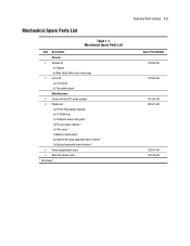
...-ROM stop c) Peripheral board card guide * d) PCI card guide retainer * e) Filter cover * f) Memory board guide * g) Optional hot-plug expansion board retainer * h) Optional expansion board retainer * 5 Power supply blank cover 6 Hard drive blank cover * Not shown Illustrated Parts Catalog 1-3 Spare Part Number 177899-001 177900-001 191444-001 187681-001 122641-001 122759...
...-ROM stop c) Peripheral board card guide * d) PCI card guide retainer * e) Filter cover * f) Memory board guide * g) Optional hot-plug expansion board retainer * h) Optional expansion board retainer * 5 Power supply blank cover 6 Hard drive blank cover * Not shown Illustrated Parts Catalog 1-3 Spare Part Number 177899-001 177900-001 191444-001 187681-001 122641-001 122759...
Service Guide
Page 14
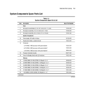
...1 ½ inch) 8 Hot-plug fan assembly, 92 x 25.4 mm (3.62 x 1 inch) 9 Hot-plug fan assembly, 80 x 20 mm (3.15 x 0.79 inch) System Components 10 Power supply, 450 watts, hot-plug 11 Replacement battery, peripheral board 12 Processors a) 700-MHz (1-MB) processor with green heatsink b) 700-MHz (2-MB) processor with green heatsink..., CL-2) * 18 512-MB DIMM (100-MHz SDRAM, 128-Megabit, CL-2) * 19 512-MB DIMM (100-MHz SDRAM, 256-Megabit, CL-2) * 20 1-GB DIMM (100-MHz SDRAM, 256-Megabit, CL-2) * * Not shown Spare Part Number 177902-001 177903-001 177901-001 101920-001 179322-001 175292-001 175293...
...1 ½ inch) 8 Hot-plug fan assembly, 92 x 25.4 mm (3.62 x 1 inch) 9 Hot-plug fan assembly, 80 x 20 mm (3.15 x 0.79 inch) System Components 10 Power supply, 450 watts, hot-plug 11 Replacement battery, peripheral board 12 Processors a) 700-MHz (1-MB) processor with green heatsink b) 700-MHz (2-MB) processor with green heatsink..., CL-2) * 18 512-MB DIMM (100-MHz SDRAM, 128-Megabit, CL-2) * 19 512-MB DIMM (100-MHz SDRAM, 256-Megabit, CL-2) * 20 1-GB DIMM (100-MHz SDRAM, 256-Megabit, CL-2) * * Not shown Spare Part Number 177902-001 177903-001 177901-001 101920-001 179322-001 175292-001 175293...
Service Guide
Page 19
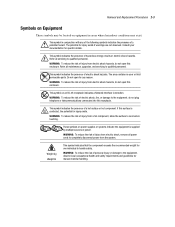
... from electric shock hazards, do not open this receptacle. The area contains no user or field serviceable parts. This symbol on power supplies or systems indicate the equipment is contacted, the potential for any of the following symbols indicates the presence of injury from the ... shock hazards. WARNING: To reduce the risk of injury from electric shock, remove all maintenance, upgrades, and servicing to completely disconnect power from electric shock hazards, do not open for injury exists. Consult your documentation for injury exists if warnings are not observed. WARNING:...
... from electric shock hazards, do not open this receptacle. The area contains no user or field serviceable parts. This symbol on power supplies or systems indicate the equipment is contacted, the potential for any of the following symbols indicates the presence of injury from the ... shock hazards. WARNING: To reduce the risk of injury from electric shock, remove all maintenance, upgrades, and servicing to completely disconnect power from electric shock hazards, do not open for injury exists. Consult your documentation for injury exists if warnings are not observed. WARNING:...
Service Guide
Page 20
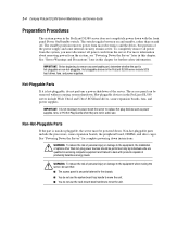
.... 2-4 Compaq ProLiant DL580 Server Maintenance and Service Guide Preparation Procedures The system power in the ProLiant DL580 server does not completely power down instructions. IMPORTANT: It is hot-pluggable, do not perform a power shutdown of personal injury or damage to the equipment when moving the server, be powered down the server to replace hot-plug devices such as power supplies, fans...
.... 2-4 Compaq ProLiant DL580 Server Maintenance and Service Guide Preparation Procedures The system power in the ProLiant DL580 server does not completely power down instructions. IMPORTANT: It is hot-pluggable, do not perform a power shutdown of personal injury or damage to the equipment when moving the server, be powered down the server to replace hot-plug devices such as power supplies, fans...
Service Guide
Page 21
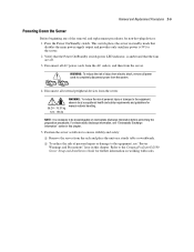
..., see "Electrostatic Discharge Information" earlier in standby mode that the fans are off. 3. Removal and Replacement Procedures 2-5 Powering Down the Server Before beginning any of personal injury or damage to the equipment, observe local occupational health and safety requirements... procedures. NOTE: It is amber and that disables the main power supply output and provides only auxiliary power (+5V) to completely disconnect power from the server. Position the server as follows to the Compaq ProLiant DL580 Server Setup and Installation Guide for further information on a sturdy ...
..., see "Electrostatic Discharge Information" earlier in standby mode that the fans are off. 3. Removal and Replacement Procedures 2-5 Powering Down the Server Before beginning any of personal injury or damage to the equipment, observe local occupational health and safety requirements... procedures. NOTE: It is amber and that disables the main power supply output and provides only auxiliary power (+5V) to completely disconnect power from the server. Position the server as follows to the Compaq ProLiant DL580 Server Setup and Installation Guide for further information on a sturdy ...
Service Guide
Page 22
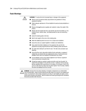
... providing for heavy equipment handling. Remove equipment from the pallet. Stabilize the server by keeping the unit on the equipment. Heed all pluggable power supplies and modules to safely unload the rack from the rack before extending a component outside the rack. Fully extend the bottom stabilizers on the rails.... The slide rails could pinch your fingertips. Do not attempt to the rack if it rolls down the ramp from the sides. 2-6 Compaq ProLiant DL580 Server Maintenance and Service Guide Rack Warnings WARNING: To reduce the risk of the rack on the leveling jacks.
... providing for heavy equipment handling. Remove equipment from the pallet. Stabilize the server by keeping the unit on the equipment. Heed all pluggable power supplies and modules to safely unload the rack from the rack before extending a component outside the rack. Fully extend the bottom stabilizers on the rails.... The slide rails could pinch your fingertips. Do not attempt to the rack if it rolls down the ramp from the sides. 2-6 Compaq ProLiant DL580 Server Maintenance and Service Guide Rack Warnings WARNING: To reduce the risk of the rack on the leveling jacks.
Service Guide
Page 23
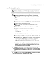
.... Verify that the AC power supply branch circuit that could bridge live parts. CAUTION: Protect the server from power fluctuations and temporary interruptions with the system unit cover on. CAUTION: The ProLiant DL580 server must always be performed by unplugging the power cord from either the electrical... outlet or the server. Do not disable the power cord grounding plug. The grounding plug is easily accessible at ...
.... Verify that the AC power supply branch circuit that could bridge live parts. CAUTION: Protect the server from power fluctuations and temporary interruptions with the system unit cover on. CAUTION: The ProLiant DL580 server must always be performed by unplugging the power cord from either the electrical... outlet or the server. Do not disable the power cord grounding plug. The grounding plug is easily accessible at ...
Service Guide
Page 40
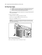
... up the release lever. 3. Removing a hot-plug power supply Reverse steps 1 through 3 to allow proper airflow. Unplug the AC power cord from the server. IMPORTANT: A power supply blank cover is fully inserted. 1 2 Figure 2-17. 2-24 Compaq ProLiant DL580 Server Maintenance and Service Guide Hot-Plug Power Supply CAUTION: If one of the power supplies is not necessary to place the system in...
... up the release lever. 3. Removing a hot-plug power supply Reverse steps 1 through 3 to allow proper airflow. Unplug the AC power cord from the server. IMPORTANT: A power supply blank cover is fully inserted. 1 2 Figure 2-17. 2-24 Compaq ProLiant DL580 Server Maintenance and Service Guide Hot-Plug Power Supply CAUTION: If one of the power supplies is not necessary to place the system in...
Service Guide
Page 44
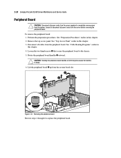
... access panel. Disconnect all power cords from the power supplies to completely remove power from the system. See "Cable Routing Diagrams" earlier in this chapter. 3. CAUTION: Rotating the peripheral board handles a full 90 degrees causes the handles to disconnect all power cords from the server before removing the peripheral board. 2-28 Compaq ProLiant DL580 Server Maintenance and Service...
... access panel. Disconnect all power cords from the power supplies to completely remove power from the system. See "Cable Routing Diagrams" earlier in this chapter. 3. CAUTION: Rotating the peripheral board handles a full 90 degrees causes the handles to disconnect all power cords from the server before removing the peripheral board. 2-28 Compaq ProLiant DL580 Server Maintenance and Service...
Service Guide
Page 49
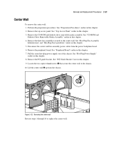
... the center wall fan assembly power cables from the chassis. 1 2 Figure 2-25. See "Hot-Plug Power Supply" earlier in this chapter. 2. Removing the center wall Reverse steps 1 through 10 to the center wall. Lift the center wall up from the power backplane board. 6. Remove the... earlier in this chapter. 4. Perform the preparation procedures. See "Top Access Panel" earlier in this chapter. 8. Pull the center hot-plug power supply out of the chassis. See "CD-ROM and Diskette Drive Removable Media Assembly" earlier in this chapter. 5. See "Peripheral Board" earlier in ...
... the center wall fan assembly power cables from the chassis. 1 2 Figure 2-25. See "Hot-Plug Power Supply" earlier in this chapter. 2. Removing the center wall Reverse steps 1 through 10 to the center wall. Lift the center wall up from the power backplane board. 6. Remove the... earlier in this chapter. 4. Perform the preparation procedures. See "Top Access Panel" earlier in this chapter. 8. Pull the center hot-plug power supply out of the chassis. See "CD-ROM and Diskette Drive Removable Media Assembly" earlier in this chapter. 5. See "Peripheral Board" earlier in ...

Service Guide
Page 60
... power backplane board assembly. Disconnect all power supplies partially out of the unit. Removing the power backplane board from the subpan Reverse steps 1 through 6 to the backplane board subpan, then lift the backplane board from the power backplane board assembly. 6. Remove the PCI guide bracket. Remove the center wall. 2-44 Compaq ProLiant DL580 Server Maintenance and Service Guide Power...
... power backplane board assembly. Disconnect all power supplies partially out of the unit. Removing the power backplane board from the subpan Reverse steps 1 through 6 to the backplane board subpan, then lift the backplane board from the power backplane board assembly. 6. Remove the PCI guide bracket. Remove the center wall. 2-44 Compaq ProLiant DL580 Server Maintenance and Service Guide Power...
Service Guide
Page 63
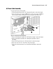
Remove the primary power supply cable and the secondary power supply cable from the two rear power outlets. See "Center Wall" earlier in this chapter. 7. See "Hot-Plug Power Supply" earlier in this chapter. 4. See "Hot-Plug Fan Assemblies" earlier in this chapter. 5. See "System Board ... earlier in this chapter. Cut the plastic tie wrap securing the cable if there is one. 2 1 Figure 2-38. Removing the AC power supply cables 3. See "PCI Guide Bracket" earlier in this chapter. 6. Perform the preparation procedures. Remove the PCI guide bracket. See "Preparation ...
Remove the primary power supply cable and the secondary power supply cable from the two rear power outlets. See "Center Wall" earlier in this chapter. 7. See "Hot-Plug Power Supply" earlier in this chapter. 4. See "Hot-Plug Fan Assemblies" earlier in this chapter. 5. See "System Board ... earlier in this chapter. Cut the plastic tie wrap securing the cable if there is one. 2 1 Figure 2-38. Removing the AC power supply cables 3. See "PCI Guide Bracket" earlier in this chapter. 6. Perform the preparation procedures. Remove the PCI guide bracket. See "Preparation ...
Service Guide
Page 65
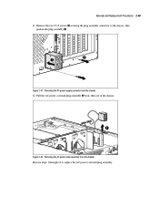
Pull the AC power cord and plug assembly back, then out of the chassis. 8 Figure 2-42. Remove the two T-15 screws securing the plug assembly connector to replace the AC power cord and plug assembly. Removing the AC power cable assembly from the chassis 12. Removal and Replacement Procedures 2-49 11. Removing the AC power supply connector from the chassis Reverse steps 1 through 12 to the chassis, then push in the plug assembly . 6 7 Figure 2-41.
Pull the AC power cord and plug assembly back, then out of the chassis. 8 Figure 2-42. Remove the two T-15 screws securing the plug assembly connector to replace the AC power cord and plug assembly. Removing the AC power cable assembly from the chassis 12. Removal and Replacement Procedures 2-49 11. Removing the AC power supply connector from the chassis Reverse steps 1 through 12 to the chassis, then push in the plug assembly . 6 7 Figure 2-41.
Service Guide
Page 76
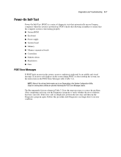
If an error code displays on Compaq computers when the system is powered up. Steps for running these utilities are provided following assemblies to verify whether the error condition has been corrected. The Recommended Action column in Table 3-2 ... this procedure until Diagnostics no longer detects an error condition. NOTE: Many of diagnostic tests that the computer system is functioning properly: System ROM Keyboard Power supply System board Memory Memory expansion boards Controllers Diskette drives Hard drives Fans POST Error Messages If POST finds an error in the POST Error Messages...
If an error code displays on Compaq computers when the system is powered up. Steps for running these utilities are provided following assemblies to verify whether the error condition has been corrected. The Recommended Action column in Table 3-2 ... this procedure until Diagnostics no longer detects an error condition. NOTE: Many of diagnostic tests that the computer system is functioning properly: System ROM Keyboard Power supply System board Memory Memory expansion boards Controllers Diskette drives Hard drives Fans POST Error Messages If POST finds an error in the POST Error Messages...
Service Guide
Page 80
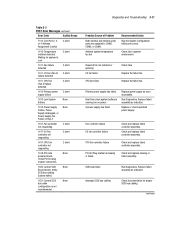
...2 short failure detected 1611-CPU Fan (Fan X) failure detected 2 short 1612-Primary power 2 short supply failure 1613-Low System None Battery 1615-Power Supply None Failure, Power Supply Unplugged, or Power Supply Fan Failure in system environment. Replace failed assembly as indicated. Verify SCSI bus cabling.... Replace failed assembly as indicated. Check PCI hot plug enabler connectors. 1620-Locked SCSI None Bus Detected. Primary power supply has failed. Check and replace failed controller assembly. Diagnostics and Troubleshooting 3-11 Table 3-2 POST Error Messages continued ...
...2 short failure detected 1611-CPU Fan (Fan X) failure detected 2 short 1612-Primary power 2 short supply failure 1613-Low System None Battery 1615-Power Supply None Failure, Power Supply Unplugged, or Power Supply Fan Failure in system environment. Replace failed assembly as indicated. Verify SCSI bus cabling.... Replace failed assembly as indicated. Check PCI hot plug enabler connectors. 1620-Locked SCSI None Bus Detected. Primary power supply has failed. Check and replace failed controller assembly. Diagnostics and Troubleshooting 3-11 Table 3-2 POST Error Messages continued ...
Service Guide
Page 114
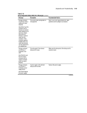
... enclosure door is closed or the side panel is securely closed. Replace the power supply. Make sure the side panel of the external storage unit is not supported. SOLUTION: Replace the power supply. If this controller supports multiple buses, the cable disconnected can be reattached to... your user documentation for cable guidelines and reconfigure as indicated. A power supply in the external storage unit has failed. Please disconnect the internal or external cable from the controller. Refer to an ...
... enclosure door is closed or the side panel is securely closed. Replace the power supply. Make sure the side panel of the external storage unit is not supported. SOLUTION: Replace the power supply. If this controller supports multiple buses, the cable disconnected can be reattached to... your user documentation for cable guidelines and reconfigure as indicated. A power supply in the external storage unit has failed. Please disconnect the internal or external cable from the controller. Refer to an ...
Service Guide
Page 125
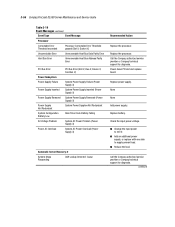
... Compaq ProLiant DL580 Server Maintenance and Service Guide Table 3-19 Event Messages continued Event Type Event Message Processor Correctable Error Threshold exceeded Processor Correctable Error Threshold passed (Slot X, Socket X) Uncorrectable Error Unrecoverable Host Bus Data Parity Error Host Bus Error Unrecoverable Host Bus Address Parity Error PCI Bus Error Power Subsystem Power Supply Failure Power Supply Inserted Power Supply Removed Power Supply...
... Compaq ProLiant DL580 Server Maintenance and Service Guide Table 3-19 Event Messages continued Event Type Event Message Processor Correctable Error Threshold exceeded Processor Correctable Error Threshold passed (Slot X, Socket X) Uncorrectable Error Unrecoverable Host Bus Data Parity Error Host Bus Error Unrecoverable Host Bus Address Parity Error PCI Bus Error Power Subsystem Power Supply Failure Power Supply Inserted Power Supply Removed Power Supply...

