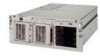
Service Guide
Page 4
...Compaq ProLiant DL580 Server Maintenance and Service Guide Removal and Replacement Procedures continued Cable Routing Diagrams 2-20 24X or Higher Low-Profile CD-ROM Signal and Power Cables 2-20 Diskette Drive Signal and Power Cables 2-20 Power Switch Cables 2-21 Power Backplane Board Cables 2-22 Peripheral Board Data Cables 2-23 Hot-Plug Power Supply...Utilities Access...3-5 Running the Utilities from the System Partition 3-5 Running the Utilities from Diskette 3-6 Running the Utilities from the Compaq SmartStart and Support Software CD 3-6 Power-On Self-Test 3-7 POST Error Messages 3-7
...Compaq ProLiant DL580 Server Maintenance and Service Guide Removal and Replacement Procedures continued Cable Routing Diagrams 2-20 24X or Higher Low-Profile CD-ROM Signal and Power Cables 2-20 Diskette Drive Signal and Power Cables 2-20 Power Switch Cables 2-21 Power Backplane Board Cables 2-22 Peripheral Board Data Cables 2-23 Hot-Plug Power Supply...Utilities Access...3-5 Running the Utilities from the System Partition 3-5 Running the Utilities from Diskette 3-6 Running the Utilities from the Compaq SmartStart and Support Software CD 3-6 Power-On Self-Test 3-7 POST Error Messages 3-7
Service Guide
Page 6
vi Compaq ProLiant DL580 Server Maintenance and Service Guide Connectors, Switches, and LED Indicators continued LED Indicators ...4-11 Front Bezel LED Indicators 4-12 Interlock Status LED Indicators 4-13 Internal Diagnostics Display Indicator 4-14 Hot-Plug Power Supply LED Indicators 4-15 Hot-Plug Fan LED Indicators... Drive and CD-ROM LED Indicators 4-20 Chapter 5 Physical and Operating Specifications System Unit ...5-2 Hot-Plug Hard Drives 5-3 Hot-Plug Power Supply 5-4 Memory ...5-5 1.44-MB Diskette Drive 5-5 24X Low-Profile CD-ROM Drive 5-6 NC3134 Fast Ethernet NIC 64 PCI Dual Base ...
vi Compaq ProLiant DL580 Server Maintenance and Service Guide Connectors, Switches, and LED Indicators continued LED Indicators ...4-11 Front Bezel LED Indicators 4-12 Interlock Status LED Indicators 4-13 Internal Diagnostics Display Indicator 4-14 Hot-Plug Power Supply LED Indicators 4-15 Hot-Plug Fan LED Indicators... Drive and CD-ROM LED Indicators 4-20 Chapter 5 Physical and Operating Specifications System Unit ...5-2 Hot-Plug Hard Drives 5-3 Hot-Plug Power Supply 5-4 Memory ...5-5 1.44-MB Diskette Drive 5-5 24X Low-Profile CD-ROM Drive 5-6 NC3134 Fast Ethernet NIC 64 PCI Dual Base ...
Service Guide
Page 8
... a safety hazard. Plug the power cord into a properly grounded AC outlet only. The racks are attached to allow only subassembly/module level repair. A rack may void any warranty. viii Compaq ProLiant DL580 Server Maintenance and Service Guide Compaq Technician Notes WARNING: Only authorized ... shock or damage to the equipment: If the system has multiple power supplies, disconnect power from the system by Compaq should attempt to make modifications to make repairs at all power cords from the power supplies. CAUTION: To properly ventilate your system, you must provide at least...
... a safety hazard. Plug the power cord into a properly grounded AC outlet only. The racks are attached to allow only subassembly/module level repair. A rack may void any warranty. viii Compaq ProLiant DL580 Server Maintenance and Service Guide Compaq Technician Notes WARNING: Only authorized ... shock or damage to the equipment: If the system has multiple power supplies, disconnect power from the system by Compaq should attempt to make modifications to make repairs at all power cords from the power supplies. CAUTION: To properly ventilate your system, you must provide at least...
Service Guide
Page 12
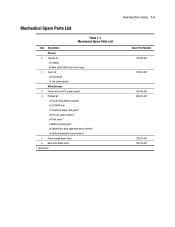
...-ROM stop c) Peripheral board card guide * d) PCI card guide retainer * e) Filter cover * f) Memory board guide * g) Optional hot-plug expansion board retainer * h) Optional expansion board retainer * 5 Power supply blank cover 6 Hard drive blank cover * Not shown Illustrated Parts Catalog 1-3 Spare Part Number 177899-001 177900-001 191444-001 187681-001 122641-001 122759...
...-ROM stop c) Peripheral board card guide * d) PCI card guide retainer * e) Filter cover * f) Memory board guide * g) Optional hot-plug expansion board retainer * h) Optional expansion board retainer * 5 Power supply blank cover 6 Hard drive blank cover * Not shown Illustrated Parts Catalog 1-3 Spare Part Number 177899-001 177900-001 191444-001 187681-001 122641-001 122759...
Service Guide
Page 14
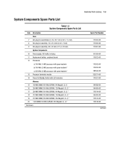
...1 ½ inch) 8 Hot-plug fan assembly, 92 x 25.4 mm (3.62 x 1 inch) 9 Hot-plug fan assembly, 80 x 20 mm (3.15 x 0.79 inch) System Components 10 Power supply, 450 watts, hot-plug 11 Replacement battery, peripheral board 12 Processors a) 700-MHz (1-MB) processor with green heatsink b) 700-MHz (2-MB) processor with green heatsink..., CL-2) * 18 512-MB DIMM (100-MHz SDRAM, 128-Megabit, CL-2) * 19 512-MB DIMM (100-MHz SDRAM, 256-Megabit, CL-2) * 20 1-GB DIMM (100-MHz SDRAM, 256-Megabit, CL-2) * * Not shown Spare Part Number 177902-001 177903-001 177901-001 101920-001 179322-001 175292-001 175293...
...1 ½ inch) 8 Hot-plug fan assembly, 92 x 25.4 mm (3.62 x 1 inch) 9 Hot-plug fan assembly, 80 x 20 mm (3.15 x 0.79 inch) System Components 10 Power supply, 450 watts, hot-plug 11 Replacement battery, peripheral board 12 Processors a) 700-MHz (1-MB) processor with green heatsink b) 700-MHz (2-MB) processor with green heatsink..., CL-2) * 18 512-MB DIMM (100-MHz SDRAM, 128-Megabit, CL-2) * 19 512-MB DIMM (100-MHz SDRAM, 256-Megabit, CL-2) * 20 1-GB DIMM (100-MHz SDRAM, 256-Megabit, CL-2) * * Not shown Spare Part Number 177902-001 177903-001 177901-001 101920-001 179322-001 175292-001 175293...
Service Guide
Page 19
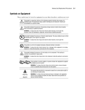
... the risk of injury from a hot component, allow the surface to qualified personnel. Do not open this enclosure. These symbols on power supplies or systems indicate the equipment is contacted, the potential for any of the following symbols indicates the presence of a potential hazard. Consult...symbol indicates the presence of injury from electric shock, remove all power cords to handle safely. Refer all servicing to the equipment, do not plug telephone or telecommunications connectors into this surface is supplied by multiple sources of injury from the system. WARNING: To ...
... the risk of injury from a hot component, allow the surface to qualified personnel. Do not open this enclosure. These symbols on power supplies or systems indicate the equipment is contacted, the potential for any of the following symbols indicates the presence of a potential hazard. Consult...symbol indicates the presence of injury from electric shock, remove all power cords to handle safely. Refer all servicing to the equipment, do not plug telephone or telecommunications connectors into this surface is supplied by multiple sources of injury from the system. WARNING: To ...
Service Guide
Page 20
... hard drives, some expansion boards, the peripheral board, DIMMs, and drive cages. 2-4 Compaq ProLiant DL580 Server Maintenance and Service Guide Preparation Procedures The system power in the ProLiant DL580 server does not completely power down the server to replace hot-plug devices such as power supplies, fans, or PCI Hot Plug boards when they are qualified in this chapter...
... hard drives, some expansion boards, the peripheral board, DIMMs, and drive cages. 2-4 Compaq ProLiant DL580 Server Maintenance and Service Guide Preparation Procedures The system power in the ProLiant DL580 server does not completely power down the server to replace hot-plug devices such as power supplies, fans, or PCI Hot Plug boards when they are qualified in this chapter...
Service Guide
Page 21
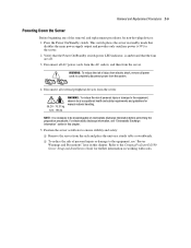
...off. 3. Refer to the Compaq ProLiant DL580 Server Setup and Installation Guide for further information on a sturdy table or workbench. Verify that disables the main power supply output and provides only auxiliary power (+5V) to the server. 2. Disconnect all AC power cords from the AC outlets...material handling. Position the server as follows to ensure stability and safety: Remove the server from the system. 4. Disconnect all power cords to the equipment, see "Electrostatic Discharge Information" earlier in this chapter. 5. For electrostatic discharge information, see "Server ...
...off. 3. Refer to the Compaq ProLiant DL580 Server Setup and Installation Guide for further information on a sturdy table or workbench. Verify that disables the main power supply output and provides only auxiliary power (+5V) to the server. 2. Disconnect all AC power cords from the AC outlets...material handling. Position the server as follows to ensure stability and safety: Remove the server from the system. 4. Disconnect all power cords to the equipment, see "Electrostatic Discharge Information" earlier in this chapter. 5. For electrostatic discharge information, see "Server ...
Service Guide
Page 22
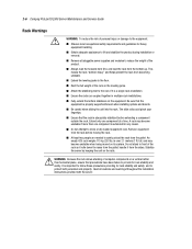
...the pallet. It is over 2.1 meters (7 ft) tall, and may become unstable when being moved on the rails. Heed all pluggable power supplies and modules to reduce the weight of the product. An empty 42U rack weighs 115 kg (253 lb), is important to follow these ... and boards. Remove all cautions and warnings throughout the installation instructions provided with the server. Do not attempt to the floor. 2-6 Compaq ProLiant DL580 Server Maintenance and Service Guide Rack Warnings WARNING: To reduce the risk of personal injury or damage to the equipment: Observe local occupational...
...the pallet. It is over 2.1 meters (7 ft) tall, and may become unstable when being moved on the rails. Heed all pluggable power supplies and modules to reduce the weight of the product. An empty 42U rack weighs 115 kg (253 lb), is important to follow these ... and boards. Remove all cautions and warnings throughout the installation instructions provided with the server. Do not attempt to the floor. 2-6 Compaq ProLiant DL580 Server Maintenance and Service Guide Rack Warnings WARNING: To reduce the risk of personal injury or damage to the equipment: Observe local occupational...
Service Guide
Page 23
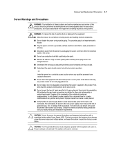
... -OrInstall the server in a controlled access location where only qualified personnel have access to make repairs at all AC power cords. CAUTION: The ProLiant DL580 server must always be performed by individuals who are detailed to the rack is not overloaded. Proper cooling is not ... and touching internal components. Improper repairs can create a safety hazard. Verify that the AC power supply branch circuit that could bridge live parts. Not overloading AC power to the rack power supply circuit reduces the risk of personal injury, fire, or damage to hazardous energy circuits. This...
... -OrInstall the server in a controlled access location where only qualified personnel have access to make repairs at all AC power cords. CAUTION: The ProLiant DL580 server must always be performed by individuals who are detailed to the rack is not overloaded. Proper cooling is not ... and touching internal components. Improper repairs can create a safety hazard. Verify that the AC power supply branch circuit that could bridge live parts. Not overloading AC power to the rack power supply circuit reduces the risk of personal injury, fire, or damage to hazardous energy circuits. This...
Service Guide
Page 40
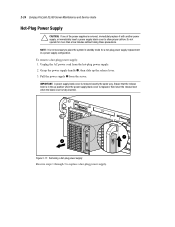
... a power supply configuration. 2-24 Compaq ProLiant DL580 Server Maintenance and Service Guide Hot-Plug Power Supply CAUTION: If one of the power supplies is removed, immediately replace it with another power supply, or immediately insert a power supply blank cover to replace a hot-plug power supply. To remove a hot-plug power supply: 1. Unplug the AC power cord from the server. Grasp the power supply handle , then slide up position when the power supply...
... a power supply configuration. 2-24 Compaq ProLiant DL580 Server Maintenance and Service Guide Hot-Plug Power Supply CAUTION: If one of the power supplies is removed, immediately replace it with another power supply, or immediately insert a power supply blank cover to replace a hot-plug power supply. To remove a hot-plug power supply: 1. Unplug the AC power cord from the server. Grasp the power supply handle , then slide up position when the power supply...
Service Guide
Page 44
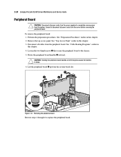
... 6 to the chassis. 5. See "Preparation Procedures" earlier in this chapter. 4. Disconnect all cables from the system. 2-28 Compaq ProLiant DL580 Server Maintenance and Service Guide Peripheral Board CAUTION: Disconnect all power cords from the power supplies to completely remove power from the peripheral board. Remove the top access panel. Ensure to break. 6. Lift the peripheral board up...
... 6 to the chassis. 5. See "Preparation Procedures" earlier in this chapter. 4. Disconnect all cables from the system. 2-28 Compaq ProLiant DL580 Server Maintenance and Service Guide Peripheral Board CAUTION: Disconnect all power cords from the power supplies to completely remove power from the peripheral board. Remove the top access panel. Ensure to break. 6. Lift the peripheral board up...
Service Guide
Page 49
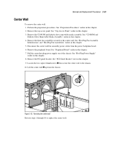
...8. Remove the top access panel. See "Peripheral Board" earlier in this chapter. 3. See "Hot-Plug Power Supply" earlier in this chapter. 5. Lift the center wall up from the power backplane board. 6. Perform the preparation procedures. See "CD-ROM and Diskette Drive Removable Media Assembly" earlier in...Plug Fan Assembly Identification" and "Hot-Plug Fan Assemblies" earlier in this chapter. 2. Pull the center hot-plug power supply out of the chassis. Remove the PCI guide bracket. See "Preparation Procedures" earlier in this chapter. 4. Disconnect the center wall fan ...
...8. Remove the top access panel. See "Peripheral Board" earlier in this chapter. 3. See "Hot-Plug Power Supply" earlier in this chapter. 5. Lift the center wall up from the power backplane board. 6. Perform the preparation procedures. See "CD-ROM and Diskette Drive Removable Media Assembly" earlier in...Plug Fan Assembly Identification" and "Hot-Plug Fan Assemblies" earlier in this chapter. 2. Pull the center hot-plug power supply out of the chassis. Remove the PCI guide bracket. See "Preparation Procedures" earlier in this chapter. 4. Disconnect the center wall fan ...

Service Guide
Page 60
... 6 to the backplane board subpan, then lift the backplane board from the power backplane board assembly. 6. Remove the PCI guide bracket. Disconnect all power supplies partially out of the unit. 2-44 Compaq ProLiant DL580 Server Maintenance and Service Guide Power Backplane Board To remove the power backplane board: 1. Remove the center wall. See "PCI Guide Bracket" earlier in...
... 6 to the backplane board subpan, then lift the backplane board from the power backplane board assembly. 6. Remove the PCI guide bracket. Disconnect all power supplies partially out of the unit. 2-44 Compaq ProLiant DL580 Server Maintenance and Service Guide Power Backplane Board To remove the power backplane board: 1. Remove the center wall. See "PCI Guide Bracket" earlier in...
Service Guide
Page 63
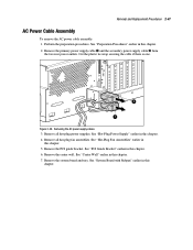
... and tray. Perform the preparation procedures. See "Hot-Plug Fan Assemblies" earlier in this chapter. 5. See "Center Wall" earlier in this chapter. 7. Removing the AC power supply cables 3. Remove the center wall. Remove the PCI guide bracket. See "System Board with Subpan" earlier in this chapter. Removal and Replacement Procedures 2-47 AC...
... and tray. Perform the preparation procedures. See "Hot-Plug Fan Assemblies" earlier in this chapter. 5. See "Center Wall" earlier in this chapter. 7. Removing the AC power supply cables 3. Remove the center wall. Remove the PCI guide bracket. See "System Board with Subpan" earlier in this chapter. Removal and Replacement Procedures 2-47 AC...
Service Guide
Page 65
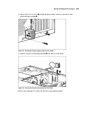
Remove the two T-15 screws securing the plug assembly connector to replace the AC power cord and plug assembly. Removing the AC power supply connector from the chassis Reverse steps 1 through 12 to the chassis, then push in the plug assembly . 6 7 Figure 2-41. Removing the AC power cable assembly from the chassis 12. Removal and Replacement Procedures 2-49 11. Pull the AC power cord and plug assembly back, then out of the chassis. 8 Figure 2-42.
Remove the two T-15 screws securing the plug assembly connector to replace the AC power cord and plug assembly. Removing the AC power supply connector from the chassis Reverse steps 1 through 12 to the chassis, then push in the plug assembly . 6 7 Figure 2-41. Removing the AC power cable assembly from the chassis 12. Removal and Replacement Procedures 2-49 11. Pull the AC power cord and plug assembly back, then out of the chassis. 8 Figure 2-42.
Service Guide
Page 76
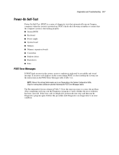
If an error code displays on Compaq computers when the system is powered up. After completing each step, run the Diagnostics program again. If the error code is redisplayed, perform the next step, and then run the Diagnostics ... this procedure until Diagnostics no longer detects an error condition. NOTE: Many of diagnostic tests that the computer system is functioning properly: System ROM Keyboard Power supply System board Memory Memory expansion boards Controllers Diskette drives Hard drives Fans POST Error Messages If POST finds an error in the system, an error...
If an error code displays on Compaq computers when the system is powered up. After completing each step, run the Diagnostics program again. If the error code is redisplayed, perform the next step, and then run the Diagnostics ... this procedure until Diagnostics no longer detects an error condition. NOTE: Many of diagnostic tests that the computer system is functioning properly: System ROM Keyboard Power supply System board Memory Memory expansion boards Controllers Diskette drives Hard drives Fans POST Error Messages If POST finds an error in the system, an error...
Service Guide
Page 80
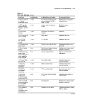
... cabling. Check and replace failed controller assembly. SCSI bus failure Run Diagnostics. Verify SCSI bus cabling. Primary power supply has failed. Diagnostics and Troubleshooting 3-11 Table 3-2 POST Error Messages continued Error Code Audible Beeps 1152-Com ...failure detected 1611-CPU Fan (Fan X) failure detected 2 short 1612-Primary power 2 short supply failure 1613-Low System None Battery 1615-Power Supply None Failure, Power Supply Unplugged, or Power Supply Fan Failure in system environment. Replace failed assembly as indicated. Fan controller failure...
... cabling. Check and replace failed controller assembly. SCSI bus failure Run Diagnostics. Verify SCSI bus cabling. Primary power supply has failed. Diagnostics and Troubleshooting 3-11 Table 3-2 POST Error Messages continued Error Code Audible Beeps 1152-Com ...failure detected 1611-CPU Fan (Fan X) failure detected 2 short 1612-Primary power 2 short supply failure 1613-Low System None Battery 1615-Power Supply None Failure, Power Supply Unplugged, or Power Supply Fan Failure in system environment. Replace failed assembly as indicated. Fan controller failure...
Service Guide
Page 114
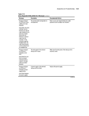
...) Error Messages continued Message Description Recommended Action Storage enclosure on SCSI bus X indicated a power supply failure. Storage enclosure on SCSI bus X has a cabling error (bus disabled). Replace the power supply. A power supply in the external storage unit has failed. The side panel of the storage unit is ...securely closed or the side panel is closed . SOLUTION: Replace the power supply. Refer to an available bus. Storage enclosure on SCSI bus X indicated a door alert. SOLUTION: The SCSI controller has an...
...) Error Messages continued Message Description Recommended Action Storage enclosure on SCSI bus X indicated a power supply failure. Storage enclosure on SCSI bus X has a cabling error (bus disabled). Replace the power supply. A power supply in the external storage unit has failed. The side panel of the storage unit is ...securely closed or the side panel is closed . SOLUTION: Replace the power supply. Refer to an available bus. Storage enclosure on SCSI bus X indicated a door alert. SOLUTION: The SCSI controller has an...
Service Guide
Page 125
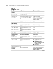
... Compaq ProLiant DL580 Server Maintenance and Service Guide Table 3-19 Event Messages continued Event Type Event Message Processor Correctable Error Threshold exceeded Processor Correctable Error Threshold passed (Slot X, Socket X) Uncorrectable Error Unrecoverable Host Bus Data Parity Error Host Bus Error Unrecoverable Host Bus Address Parity Error PCI Bus Error Power Subsystem Power Supply Failure Power Supply Inserted Power Supply Removed Power Supply...
... Compaq ProLiant DL580 Server Maintenance and Service Guide Table 3-19 Event Messages continued Event Type Event Message Processor Correctable Error Threshold exceeded Processor Correctable Error Threshold passed (Slot X, Socket X) Uncorrectable Error Unrecoverable Host Bus Data Parity Error Host Bus Error Unrecoverable Host Bus Address Parity Error PCI Bus Error Power Subsystem Power Supply Failure Power Supply Inserted Power Supply Removed Power Supply...

