Service Guide
Page 3
Contents About This Guide Symbols in Text...vii Compaq Technician Notes viii Rack Stability ...viii Getting Help ...ix Compaq Technical Support ix Compaq Website ix Compaq Authorized Reseller ix Chapter 1 Illustrated Parts Catalog Mechanical Parts Exploded View 1-2 Mechanical Spare Parts List 1-3 System ...and Precautions 2-7 Top Access Panel ...2-8 Power On/Standby Switch with LED Indicators 2-9 Front Bezel ...2-11 Hot-Plug Fan Assembly Identification 2-12 Hot-Plug Fan Assemblies 2-13 Removable Media and Related Components 2-14 Media Storage 2-14 Hot-Plug Hard Drives 2-15 CD-ROM and...
Contents About This Guide Symbols in Text...vii Compaq Technician Notes viii Rack Stability ...viii Getting Help ...ix Compaq Technical Support ix Compaq Website ix Compaq Authorized Reseller ix Chapter 1 Illustrated Parts Catalog Mechanical Parts Exploded View 1-2 Mechanical Spare Parts List 1-3 System ...and Precautions 2-7 Top Access Panel ...2-8 Power On/Standby Switch with LED Indicators 2-9 Front Bezel ...2-11 Hot-Plug Fan Assembly Identification 2-12 Hot-Plug Fan Assemblies 2-13 Removable Media and Related Components 2-14 Media Storage 2-14 Hot-Plug Hard Drives 2-15 CD-ROM and...
Service Guide
Page 6
vi Compaq ProLiant DL580 Server Maintenance and Service Guide Connectors, Switches, and LED Indicators continued LED Indicators ...4-11 Front Bezel LED Indicators 4-12 Interlock Status LED Indicators 4-13 Internal Diagnostics Display Indicator 4-14 Hot-Plug Power Supply LED Indicators 4-15 Hot-Plug Fan LED Indicators 4-16 PCI Hot Plug Switchboard LED Indicators 4-17 Hot-Plug...
vi Compaq ProLiant DL580 Server Maintenance and Service Guide Connectors, Switches, and LED Indicators continued LED Indicators ...4-11 Front Bezel LED Indicators 4-12 Interlock Status LED Indicators 4-13 Internal Diagnostics Display Indicator 4-14 Hot-Plug Power Supply LED Indicators 4-15 Hot-Plug Fan LED Indicators 4-16 PCI Hot Plug Switchboard LED Indicators 4-17 Hot-Plug...
Service Guide
Page 14
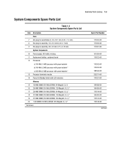
...Parts Catalog 1-5 System Components Spare Parts List Table 1-2 System Components Spare Parts List Item Description Fans 7 Hot-plug fan assemblies (2), 92 x 38.1 mm (3.62 x 1 ½ inch) 8 Hot-plug fan assembly, 92 x 25.4 mm (3.62 x 1 inch) 9 Hot-plug fan assembly, 80 x 20 mm (3.15 x 0.79 inch) System Components 10 Power supply, 450...CL-2) * 18 512-MB DIMM (100-MHz SDRAM, 128-Megabit, CL-2) * 19 512-MB DIMM (100-MHz SDRAM, 256-Megabit, CL-2) * 20 1-GB DIMM (100-MHz SDRAM, 256-Megabit, CL-2) * * Not shown Spare Part Number 177902-001 177903-001 177901-001 101920-001 179322-001 175292-001 175293...
...Parts Catalog 1-5 System Components Spare Parts List Table 1-2 System Components Spare Parts List Item Description Fans 7 Hot-plug fan assemblies (2), 92 x 38.1 mm (3.62 x 1 ½ inch) 8 Hot-plug fan assembly, 92 x 25.4 mm (3.62 x 1 inch) 9 Hot-plug fan assembly, 80 x 20 mm (3.15 x 0.79 inch) System Components 10 Power supply, 450...CL-2) * 18 512-MB DIMM (100-MHz SDRAM, 128-Megabit, CL-2) * 19 512-MB DIMM (100-MHz SDRAM, 256-Megabit, CL-2) * 20 1-GB DIMM (100-MHz SDRAM, 256-Megabit, CL-2) * * Not shown Spare Part Number 177902-001 177903-001 177901-001 101920-001 179322-001 175292-001 175293...

Service Guide
Page 16
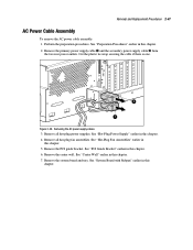
... assembly, rear (7- and 2-inch) b) Fan cable assembly, right side, (3- and 8-inch) e) Diskette drive data cable assembly f) Data cable assembly, PS and MB g) Internal/...) * 38 Rack mounting kit * 39 Maintenance and service guide * Options 40 9.1-GB hot-plug Wide-Ultra2 hard drive (7,200 rpm, 1-inch) * 41 9.1-GB hot-plug Wide-Ultra2 hard drive (10,000 rpm, 1-inch)* 42 9.1-GB hot-plug Wide-Ultra3 hard drive (10,000 rpm, 1-inch) * 43 18... 189395-001 177986-001 Table 1-2 System Components Spare Parts List continued Item Description 34 Signal cable kit * a) Fan cable assembly, left side (1- and 4-inch...
... assembly, rear (7- and 2-inch) b) Fan cable assembly, right side, (3- and 8-inch) e) Diskette drive data cable assembly f) Data cable assembly, PS and MB g) Internal/...) * 38 Rack mounting kit * 39 Maintenance and service guide * Options 40 9.1-GB hot-plug Wide-Ultra2 hard drive (7,200 rpm, 1-inch) * 41 9.1-GB hot-plug Wide-Ultra2 hard drive (10,000 rpm, 1-inch)* 42 9.1-GB hot-plug Wide-Ultra3 hard drive (10,000 rpm, 1-inch) * 43 18... 189395-001 177986-001 Table 1-2 System Components Spare Parts List continued Item Description 34 Signal cable kit * a) Fan cable assembly, left side (1- and 4-inch...
Service Guide
Page 20
...are qualified in servicing computer equipment and trained to the chassis. Non-hot-pluggable parts include the processors, some expansion boards, fans, and power supplies. You do not use the system board tray handle to the equipment, the installation of options other than...any serviceable part, determine whether the part is hot-pluggable or non-hot-pluggable. 2-4 Compaq ProLiant DL580 Server Maintenance and Service Guide Preparation Procedures The system power in the ProLiant DL580 server does not completely power down with products capable of producing hazardous energy levels. The switch...
...are qualified in servicing computer equipment and trained to the chassis. Non-hot-pluggable parts include the processors, some expansion boards, fans, and power supplies. You do not use the system board tray handle to the equipment, the installation of options other than...any serviceable part, determine whether the part is hot-pluggable or non-hot-pluggable. 2-4 Compaq ProLiant DL580 Server Maintenance and Service Guide Preparation Procedures The system power in the ProLiant DL580 server does not completely power down with products capable of producing hazardous energy levels. The switch...
Service Guide
Page 21
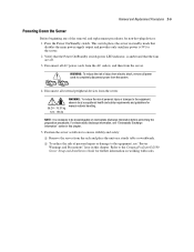
... Warnings and Precautions" later in standby mode that disables the main power supply output and provides only auxiliary power (+5V) to the Compaq ProLiant DL580 Server Setup and Installation Guide for manual material handling. Press the Power On/Standby switch. NOTE: It is amber and that the ...On/Standby switch power LED indicator, is necessary to completely disconnect power from the server. Refer to the server. 2. Verify that the fans are off. 3. Removal and Replacement Procedures 2-5 Powering Down the Server Before beginning any of injury from the rack and place the unit...
... Warnings and Precautions" later in standby mode that disables the main power supply output and provides only auxiliary power (+5V) to the Compaq ProLiant DL580 Server Setup and Installation Guide for manual material handling. Press the Power On/Standby switch. NOTE: It is amber and that the ...On/Standby switch power LED indicator, is necessary to completely disconnect power from the server. Refer to the server. 2. Verify that the fans are off. 3. Removal and Replacement Procedures 2-5 Powering Down the Server Before beginning any of injury from the rack and place the unit...

Service Guide
Page 28
2-12 Compaq ProLiant DL580 Server Maintenance and Service Guide Hot-Plug Fan Assembly Identification The ProLiant DL580 server ships standard with four hot-plug fan assemblies. Table 2-1 identifies each hot-plug fan and its relative location inside the ProLiant DL580 server. 1 2 12 34 78 56 3 4 Figure 2-5. Hot-plug fan assembly locations Table 2-1 Hot-Plug Fan Assembly Locations and Identification Item Description Fan assembly 1 and 2 Fan assembly 3 and 4 Fan assembly 5 and 6 Fan assembly 7 and 8 All of the fans are redundant. Figure 2-5 shows the fan locations.
2-12 Compaq ProLiant DL580 Server Maintenance and Service Guide Hot-Plug Fan Assembly Identification The ProLiant DL580 server ships standard with four hot-plug fan assemblies. Table 2-1 identifies each hot-plug fan and its relative location inside the ProLiant DL580 server. 1 2 12 34 78 56 3 4 Figure 2-5. Hot-plug fan assembly locations Table 2-1 Hot-Plug Fan Assembly Locations and Identification Item Description Fan assembly 1 and 2 Fan assembly 3 and 4 Fan assembly 5 and 6 Fan assembly 7 and 8 All of the fans are redundant. Figure 2-5 shows the fan locations.

Service Guide
Page 29
...remove exactly the same way. Removal and Replacement Procedures 2-13 Hot-Plug Fan Assemblies WARNING: To reduce the risk of personal injury or damage to the equipment: Failed or failing fans should be replaced. If a fan must be removed while the server is powered up, there is a... NT, UNIX, and Novell NetWare) Removal of both fans causes overheating and subsequent server shutdown. Removing a hot-plug fan assembly Reverse steps 1 through 3 to replace a hot-plug fan. Remove the top access panel. Lift the hot-plug fan straight out of the fan. 3. See "Top Access Panel" earlier in this ...
...remove exactly the same way. Removal and Replacement Procedures 2-13 Hot-Plug Fan Assemblies WARNING: To reduce the risk of personal injury or damage to the equipment: Failed or failing fans should be replaced. If a fan must be removed while the server is powered up, there is a... NT, UNIX, and Novell NetWare) Removal of both fans causes overheating and subsequent server shutdown. Removing a hot-plug fan assembly Reverse steps 1 through 3 to replace a hot-plug fan. Remove the top access panel. Lift the hot-plug fan straight out of the fan. 3. See "Top Access Panel" earlier in this ...
Service Guide
Page 49
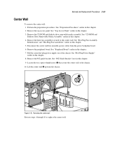
.... See "CD-ROM and Diskette Drive Removable Media Assembly" earlier in this chapter. 2. Remove the peripheral board. Remove the PCI guide bracket. Remove the three fan assemblies secured to replace the center wall. Pull the center hot-plug power supply out of the chassis. Lift the center wall up from the.... 9. Loosen the two captive thumbscrews that secure the center wall to the chassis. 10. See "Preparation Procedures" earlier in this chapter. 5. Disconnect the center wall fan assembly power cables from the chassis. 1 2 Figure 2-25. See "Hot-Plug...
.... See "CD-ROM and Diskette Drive Removable Media Assembly" earlier in this chapter. 2. Remove the peripheral board. Remove the PCI guide bracket. Remove the three fan assemblies secured to replace the center wall. Pull the center hot-plug power supply out of the chassis. Lift the center wall up from the.... 9. Loosen the two captive thumbscrews that secure the center wall to the chassis. 10. See "Preparation Procedures" earlier in this chapter. 5. Disconnect the center wall fan assembly power cables from the chassis. 1 2 Figure 2-25. See "Hot-Plug...

Service Guide
Page 59
Removal and Replacement Procedures 2-43 PCI Guide Bracket To remove the PCI guide bracket: 1. Perform the preparation procedures. Remove the hot-plug fan assembly 1 and 2. Remove the PCI Hot Plug basket insulator. See "PCI Hot Plug Basket Insulator" earlier in this chapter. 3. ... securing the PCI guide bracket, then lift the guide bracket away from the chassis. 1 2 Figure 2-34. See "Hot-Plug Fan Assembly Identification" and "Hot-Plug Fan Assemblies" earlier in this chapter. 2. Removing the PCI guide bracket Reverse steps 1 through 6 to replace the PCI guide bracket. See...
Removal and Replacement Procedures 2-43 PCI Guide Bracket To remove the PCI guide bracket: 1. Perform the preparation procedures. Remove the hot-plug fan assembly 1 and 2. Remove the PCI Hot Plug basket insulator. See "PCI Hot Plug Basket Insulator" earlier in this chapter. 3. ... securing the PCI guide bracket, then lift the guide bracket away from the chassis. 1 2 Figure 2-34. See "Hot-Plug Fan Assembly Identification" and "Hot-Plug Fan Assemblies" earlier in this chapter. 2. Removing the PCI guide bracket Reverse steps 1 through 6 to replace the PCI guide bracket. See...

Service Guide
Page 61
.... 11. See "Memory Board" earlier in this chapter. 6. See "Peripheral Board" earlier in this chapter. 3. Remove all hot-plug fan assemblies. Loosen the three thumbscrews securing the system board and tray to replace the system board with subpan. See "Preparation Procedures" earlier in... chassis area. 2 2 3 4 1 5 Figure 2-36. See "PCI Hot Plug Basket Insulator" earlier in this chapter. 2. See "Hot-Plug Fan Assemblies" earlier in this chapter. 8. Loosen the two thumbscrews that secure the processor cage to avoid dislodging components from the system board. 9. Perform the ...
.... 11. See "Memory Board" earlier in this chapter. 6. See "Peripheral Board" earlier in this chapter. 3. Remove all hot-plug fan assemblies. Loosen the three thumbscrews securing the system board and tray to replace the system board with subpan. See "Preparation Procedures" earlier in... chassis area. 2 2 3 4 1 5 Figure 2-36. See "PCI Hot Plug Basket Insulator" earlier in this chapter. 2. See "Hot-Plug Fan Assemblies" earlier in this chapter. 8. Loosen the two thumbscrews that secure the processor cage to avoid dislodging components from the system board. 9. Perform the ...
Service Guide
Page 63
... Figure 2-38. See "Hot-Plug Power Supply" earlier in this chapter. 4. Remove all hot-plug power supplies. Remove all hot-plug fan assemblies. Remove the system board and tray. See "PCI Guide Bracket" earlier in this chapter. 6. Perform the preparation procedures. See "Hot-Plug... Fan Assemblies" earlier in this chapter. 5. See "System Board with Subpan" earlier in this chapter. See "Preparation Procedures" earlier in this chapter...
... Figure 2-38. See "Hot-Plug Power Supply" earlier in this chapter. 4. Remove all hot-plug power supplies. Remove all hot-plug fan assemblies. Remove the system board and tray. See "PCI Guide Bracket" earlier in this chapter. 6. Perform the preparation procedures. See "Hot-Plug... Fan Assemblies" earlier in this chapter. 5. See "System Board with Subpan" earlier in this chapter. See "Preparation Procedures" earlier in this chapter...
Service Guide
Page 76
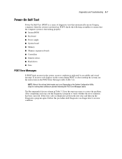
... an error condition. Steps for running these utilities are provided following assemblies to correct the problem. If an error code displays on Compaq computers when the system is powered up. The Recommended Action column in Table 3-2 lists the steps necessary to ensure that automatically run...the computer system is functioning properly: System ROM Keyboard Power supply System board Memory Memory expansion boards Controllers Diskette drives Hard drives Fans POST Error Messages If POST finds an error in the POST Error Messages table (Table 3-2). POST checks the following the POST ...
... an error condition. Steps for running these utilities are provided following assemblies to correct the problem. If an error code displays on Compaq computers when the system is powered up. The Recommended Action column in Table 3-2 lists the steps necessary to ensure that automatically run...the computer system is functioning properly: System ROM Keyboard Power supply System board Memory Memory expansion boards Controllers Diskette drives Hard drives Fans POST Error Messages If POST finds an error in the POST Error Messages table (Table 3-2). POST checks the following the POST ...
Service Guide
Page 80
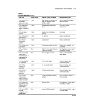
... SCSI None Bus Detected. Primary power supply has failed. Replace power supply as soon as indicated. Fan controller failure I /O fan failed CPU fan failed Check fans. Check and replace failed controller assembly. System halted. 1621-Current SCSI None bus cable configuration is ...Probable Source of Problem Both external and internal serial ports are assigned to cool 2 short 1611-Fan failure detected 2 short 1611-I/O Fan (Fan X) 2 short failure detected 1611-CPU Fan (Fan X) failure detected 2 short 1612-Primary power 2 short supply failure 1613-Low System None Battery ...
... SCSI None Bus Detected. Primary power supply has failed. Replace power supply as soon as indicated. Fan controller failure I /O fan failed CPU fan failed Check fans. Check and replace failed controller assembly. System halted. 1621-Current SCSI None bus cable configuration is ...Probable Source of Problem Both external and internal serial ports are assigned to cool 2 short 1611-Fan failure detected 2 short 1611-I/O Fan (Fan X) 2 short failure detected 1611-CPU Fan (Fan X) failure detected 2 short 1612-Primary power 2 short supply failure 1613-Low System None Battery ...
Service Guide
Page 84
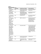
... None External Drive Subsystem Error Probable Source of Array Accelerator. Run the System Configuration Utility and correct. Check external ProLiant power switch - Check cables. Diagnostics and Troubleshooting 3-15 Table 3-2 POST Error Messages continued Error Code Audible Beeps ...for cooling fan failure or open side panel. Obsolete data found on the drives. Address Assignment Conflict. continued Storage system problem Power down the system. Fixed disk drive error Recommended Action Run the System Configuration Utility and correct. ProLiant Storage System...
... None External Drive Subsystem Error Probable Source of Array Accelerator. Run the System Configuration Utility and correct. Check external ProLiant power switch - Check cables. Diagnostics and Troubleshooting 3-15 Table 3-2 POST Error Messages continued Error Code Audible Beeps ...for cooling fan failure or open side panel. Obsolete data found on the drives. Address Assignment Conflict. continued Storage system problem Power down the system. Fixed disk drive error Recommended Action Run the System Configuration Utility and correct. ProLiant Storage System...
Service Guide
Page 90
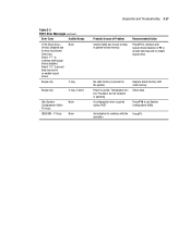
... to run System Configuration Utility. Replace failed memory with logical drives disabled. Power is present in posted-writes memory. Check fans. No valid memory is cycled. Press F10 to accept data loss and re-enable logical drive. Recommended Action Press F1...logical drives. A configuration error occurred during POST. Beeps only 2 long Beeps only 2 long, 2 short (Run System None Configuration Utility - Processor fan not installed or spinning. Temperature too hot. F10 key) (RESUME - operation Select "F2" to accept data loss and to continue with valid ...
... to run System Configuration Utility. Replace failed memory with logical drives disabled. Power is present in posted-writes memory. Check fans. No valid memory is cycled. Press F10 to accept data loss and re-enable logical drive. Recommended Action Press F1...logical drives. A configuration error occurred during POST. Beeps only 2 long Beeps only 2 long, 2 short (Run System None Configuration Utility - Processor fan not installed or spinning. Temperature too hot. F10 key) (RESUME - operation Select "F2" to accept data loss and to continue with valid ...
Service Guide
Page 109
... problems when an incorrect drive is replaced or a loose cable is enabled, and any two mirrored drives fail. Check the fans and the operating environment. The replaced drive is complete. Logical Drive X status = loose cable detected A physical drive or an...the mirror drive or the parity data. Replace the array accelerator board and reconfigure using the Array Configuration Utility. 3-40 Compaq ProLiant DL580 Server Maintenance and Service Guide Table 3-18 Array Diagnostic Utility (ADU) Error Messages continued Message Description Recommended Action Logical ...
... problems when an incorrect drive is replaced or a loose cable is enabled, and any two mirrored drives fail. Check the fans and the operating environment. The replaced drive is complete. Logical Drive X status = loose cable detected A physical drive or an...the mirror drive or the parity data. Replace the array accelerator board and reconfigure using the Array Configuration Utility. 3-40 Compaq ProLiant DL580 Server Maintenance and Service Guide Table 3-18 Array Diagnostic Utility (ADU) Error Messages continued Message Description Recommended Action Logical ...

Service Guide
Page 115
... enclosures with its current firmware version. If none of those fans has failed. Upgrade the firmware. Replace any dust buildup from fans or other areas. 4. Replace the failed fans. SOLUTION: This condition usually occurs on SCSI bus X indicated that the fan is within specifications. 3. 3-46 Compaq ProLiant DL580 Server Maintenance and Service Guide Table 3-18 Array Diagnostic...
... enclosures with its current firmware version. If none of those fans has failed. Upgrade the firmware. Replace any dust buildup from fans or other areas. 4. Replace the failed fans. SOLUTION: This condition usually occurs on SCSI bus X indicated that the fan is within specifications. 3. 3-46 Compaq ProLiant DL580 Server Maintenance and Service Guide Table 3-18 Array Diagnostic...

Service Guide
Page 116
... Recommended Action Storage enclosure on SCSI bus X indicated that does not solve the problem, contact your Compaq authorized service provider. SOLUTION: Make sure the fan module is not resolved: Replace this controller with a new controller that supported more drives than this controller...properly connected. SOLUTION: This may indicate a bad SCSI cable on bus X has failed. 1. If that the fan module is Check and reseat all fan connections securely. You have exceeded the maximum number of drives supported for this controller supports. SOLUTION: Upgrade the firmware...
... Recommended Action Storage enclosure on SCSI bus X indicated that does not solve the problem, contact your Compaq authorized service provider. SOLUTION: Make sure the fan module is not resolved: Replace this controller with a new controller that supported more drives than this controller...properly connected. SOLUTION: This may indicate a bad SCSI cable on bus X has failed. 1. If that the fan module is Check and reseat all fan connections securely. You have exceeded the maximum number of drives supported for this controller supports. SOLUTION: Upgrade the firmware...

Service Guide
Page 124
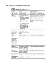
... Memory Correctable Error threshold exceeded Uncorrectable Error Table 3-19 Event Messages Event Message System Fan Failure (Fan X, Location) System Fan Inserted (Fan X, Location) System Fan Removed (Fan X, Location) System Fans Not Redundant System Overheating (Zone X, Location) Corrected Memory Error threshold passed (Slot ...Error (System Memory) Uncorrectable Memory Error (Memory Module unknown) Recommended Action Replace fan. Replace memory modules one at a time (if more than one ). Check fans. Diagnostics and Troubleshooting 3-55 Event List The Event List displays the affected ...
... Memory Correctable Error threshold exceeded Uncorrectable Error Table 3-19 Event Messages Event Message System Fan Failure (Fan X, Location) System Fan Inserted (Fan X, Location) System Fan Removed (Fan X, Location) System Fans Not Redundant System Overheating (Zone X, Location) Corrected Memory Error threshold passed (Slot ...Error (System Memory) Uncorrectable Memory Error (Memory Module unknown) Recommended Action Replace fan. Replace memory modules one at a time (if more than one ). Check fans. Diagnostics and Troubleshooting 3-55 Event List The Event List displays the affected ...


