

Product Manual
Page 1
Product Manual Router Table Model No. 320. 28180 CAUTION! Read, understand and follow all Safety Rules and Operating Instructions in this Manual before using this product. • Warranty • Safety • Assembly ° Operation o Maintenance Sears, Roebuck and Co., Hoffman Estates, IL 60179 www.craftsman.com
Product Manual Router Table Model No. 320. 28180 CAUTION! Read, understand and follow all Safety Rules and Operating Instructions in this Manual before using this product. • Warranty • Safety • Assembly ° Operation o Maintenance Sears, Roebuck and Co., Hoffman Estates, IL 60179 www.craftsman.com
Product Manual
Page 2
... it to any Sears store or parts & repair center or other reproductive harm. This warranty does not include expendable parts such as lamps, batteries, bits, or blades. This warranty gives you specific legal rights, and you may also have other rights, which vary from the date of California to state. Warranty Safety Symbols Safety Instructions Know Your Router Table Unpacking and Checking Contents Parts list Assembly Operation Maintenance Troubleshooting Page 2 Page 3-4 Page...
... it to any Sears store or parts & repair center or other reproductive harm. This warranty does not include expendable parts such as lamps, batteries, bits, or blades. This warranty gives you specific legal rights, and you may also have other rights, which vary from the date of California to state. Warranty Safety Symbols Safety Instructions Know Your Router Table Unpacking and Checking Contents Parts list Assembly Operation Maintenance Troubleshooting Page 2 Page 3-4 Page...

Product Manual
Page 4
... use in damp locations, Read the Product Manual Eye Protection Safety Alert To reduce the risk of in serious personal injury. SYMBOL V A Hz W rnin ,-,,_, no load Double-insulated construction Revolutions. per second) Power Time Type of current Type or a characteristic of current Rotational speed, at no [] _Jmin @ @ 0 A @ @ @ ® NAME DESIGNATION / EXPLANATION Volts Amperes He rtz Watt Minutes Alternating Current Direct...
... use in damp locations, Read the Product Manual Eye Protection Safety Alert To reduce the risk of in serious personal injury. SYMBOL V A Hz W rnin ,-,,_, no load Double-insulated construction Revolutions. per second) Power Time Type of current Type or a characteristic of current Rotational speed, at no [] _Jmin @ @ 0 A @ @ @ ® NAME DESIGNATION / EXPLANATION Volts Amperes He rtz Watt Minutes Alternating Current Direct...
Product Manual
Page 5
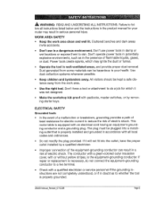
Operate the tool in well-ventilated areas, and provide proper dust removal Dust generated from the work area clean and well lit. ELECTRICALSAFETY Grounded tools In the event of a malfunction or breakdown, grounding provides a path of least resistance for electric current to reduce the risk of electric shock, This router table is equipped with a qualified electrician or service personnel if the grounding instructions are not...
Operate the tool in well-ventilated areas, and provide proper dust removal Dust generated from the work area clean and well lit. ELECTRICALSAFETY Grounded tools In the event of a malfunction or breakdown, grounding provides a path of least resistance for electric current to reduce the risk of electric shock, This router table is equipped with a qualified electrician or service personnel if the grounding instructions are not...

Product Manual
Page 6
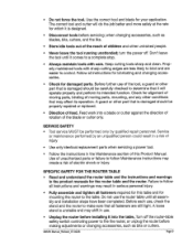
... tool is intended for the fixed-base router before operating the tool • Replacement parts: When servicing use only identical replacement parts. The green-colored rigid ear, lug, and the like the adapter illustrated in Sketches B and C, may be installed by a qualified electrician. A temporary adapter, which looks like , extending from the adapter must be sure to a permanent ground, such as shown in the figure below . o Use only 3-wire extension cords...
... tool is intended for the fixed-base router before operating the tool • Replacement parts: When servicing use only identical replacement parts. The green-colored rigid ear, lug, and the like the adapter illustrated in Sketches B and C, may be installed by a qualified electrician. A temporary adapter, which looks like , extending from the adapter must be sure to a permanent ground, such as shown in the figure below . o Use only 3-wire extension cords...

Product Manual
Page 7
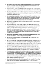
... the gauge number, the heavier the cord. Minumum Gauge for outdoor use an outdoor extension cord marked "W-A" or "W." Allowing dust to filter out microscopic particles_ Avoid prolonged contact with dust from lead-based paints. Some examples of work. AWG 18 Total Length of Cord in a well-ventilated area. • Work with approved safety equipment, such as those dust masks that are : = Lead from power sanding, sawing, grinding, drilling...
... the gauge number, the heavier the cord. Minumum Gauge for outdoor use an outdoor extension cord marked "W-A" or "W." Allowing dust to filter out microscopic particles_ Avoid prolonged contact with dust from lead-based paints. Some examples of work. AWG 18 Total Length of Cord in a well-ventilated area. • Work with approved safety equipment, such as those dust masks that are : = Lead from power sanding, sawing, grinding, drilling...

Product Manual
Page 8
... removing it frees both hands to contain long hair. WEARYOUR Wear proper apparel. Any tool that keys and adjusting wrenches are NOT safety glasses. • Never touch the pins of the electrical plug while inserting it into an electrical outlet. • Do not use the tool while tired or under the influence of unintentional starting. Non-slip footwear is recommended.Wear protective hair covering to operate tool...
... removing it frees both hands to contain long hair. WEARYOUR Wear proper apparel. Any tool that keys and adjusting wrenches are NOT safety glasses. • Never touch the pins of the electrical plug while inserting it into an electrical outlet. • Do not use the tool while tired or under the influence of unintentional starting. Non-slip footwear is recommended.Wear protective hair covering to operate tool...
Product Manual
Page 9
... the direction of rotation of children and other part that is damaged should be carefully checked to follow all assembly and installation steps have been completed. Use of feed, Feed work into the table, "['urn off the router-table safety switch controlling power to the the router, or unplug the router before servicing; Before further use the router table until it comes to a complete stop. 0 Always maintain tools with sharp cutting edges...
... the direction of rotation of children and other part that is damaged should be carefully checked to follow all assembly and installation steps have been completed. Use of feed, Feed work into the table, "['urn off the router-table safety switch controlling power to the the router, or unplug the router before servicing; Before further use the router table until it comes to a complete stop. 0 Always maintain tools with sharp cutting edges...
Product Manual
Page 10
... the work pieces. Be sure the work piece. o Install the bit in the collet chuck before making any other foreign particles that it clears the router bit and work pieces without the bit guard. Damaged bits can flip off the table or cause the table to maintain control of control. Do not cut flat, straight, and squared material. Cutting the material with the instructions in the router manual and securely clamp the router bit in...
... the work pieces. Be sure the work piece. o Install the bit in the collet chuck before making any other foreign particles that it clears the router bit and work pieces without the bit guard. Damaged bits can flip off the table or cause the table to maintain control of control. Do not cut flat, straight, and squared material. Cutting the material with the instructions in the router manual and securely clamp the router bit in...
Product Manual
Page 11
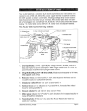
power cord (no adapter needed). Extended fence provides maximum work surface and improved sound absorption. Infeed and outfeed fence can be moved forward and backward 3-3/4 inch. 4. Miter-gauge adjusts from 0° to accommodate most fixed and plunge-based routers 2_ Integrated safety switch with an 8-ft. If the router table does not operate when plugged into correct 120-volt, 60-HZ AC ONLY outlet, check the power supply° The router table comes with...
power cord (no adapter needed). Extended fence provides maximum work surface and improved sound absorption. Infeed and outfeed fence can be moved forward and backward 3-3/4 inch. 4. Miter-gauge adjusts from 0° to accommodate most fixed and plunge-based routers 2_ Integrated safety switch with an 8-ft. If the router table does not operate when plugged into correct 120-volt, 60-HZ AC ONLY outlet, check the power supply° The router table comes with...
Product Manual
Page 12
... this table (model 17541) or the following Craftsman routers: models 17542 and 17543. _, WARNING: If any parts are missing, DO NOT attempt to assemble, install, or use your router table until the missing parts have been found or replaced and your router table comes partially assembled. * Separate all parts have been included. Dust Collection/Guard reduces dust dispersal, 11. Above-the-table height adjustment: the bit height can be adjusted by turn.. 9, Integrated switch shield prevents dust...
... this table (model 17541) or the following Craftsman routers: models 17542 and 17543. _, WARNING: If any parts are missing, DO NOT attempt to assemble, install, or use your router table until the missing parts have been found or replaced and your router table comes partially assembled. * Separate all parts have been included. Dust Collection/Guard reduces dust dispersal, 11. Above-the-table height adjustment: the bit height can be adjusted by turn.. 9, Integrated switch shield prevents dust...
Product Manual
Page 13
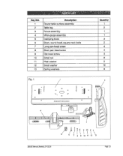
Key NO. 1 2 3 4 5 6 7 8 9 10 11 12 13 Description Router table surface assembly "Table leg Fence assembly Miter-gauge assembly Clamping knob Short, round-head, square-neck bolts Long pan-head screw Short pan-head screw Flat-head screw Small nut Plain washer Small washer Spring washers Quantity 1 2 1 1 3 2 4 4 3 8 16 8 Fig, 1 Q /1 / 1" o-=_ 3 28180 Manual Revlsed 07-0228 6 7 8 9 10 11 12 la Page13
Key NO. 1 2 3 4 5 6 7 8 9 10 11 12 13 Description Router table surface assembly "Table leg Fence assembly Miter-gauge assembly Clamping knob Short, round-head, square-neck bolts Long pan-head screw Short pan-head screw Flat-head screw Small nut Plain washer Small washer Spring washers Quantity 1 2 1 1 3 2 4 4 3 8 16 8 Fig, 1 Q /1 / 1" o-=_ 3 28180 Manual Revlsed 07-0228 6 7 8 9 10 11 12 la Page13

Product Manual
Page 14
...) onto each of two short, pan-head screws (8),Insert the short, pan-head screws up . Loosely tighten the nuts. (Fig. 2) , Place a flat washer (12) onto each of two long, pan-head screws (7). Place a small washer (12), a spring washer (13). Securely tighten all fasteners. 8. Place the router table surface upside down on a flat, level surface, with the underside of the router-table top. , Align the two outermost holes on...
...) onto each of two short, pan-head screws (8),Insert the short, pan-head screws up . Loosely tighten the nuts. (Fig. 2) , Place a flat washer (12) onto each of two long, pan-head screws (7). Place a small washer (12), a spring washer (13). Securely tighten all fasteners. 8. Place the router table surface upside down on a flat, level surface, with the underside of the router-table top. , Align the two outermost holes on...
Product Manual
Page 15
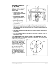
... Hold the router with the other hand. Position the router so that the table is 5-3/8"o Select three 6 71e" appropriate holes to mount the router to the router table after you . 2_ Be sure that the screw holes used for the router are not directly above either of the router sub-base does not exceed 6-7/8 inches. Remove the sub-base from the fixed-based router supplied. Insert a flat-head screw through each flat-head screw (9) with...
... Hold the router with the other hand. Position the router so that the table is 5-3/8"o Select three 6 71e" appropriate holes to mount the router to the router table after you . 2_ Be sure that the screw holes used for the router are not directly above either of the router sub-base does not exceed 6-7/8 inches. Remove the sub-base from the fixed-based router supplied. Insert a flat-head screw through each flat-head screw (9) with...

Product Manual
Page 16
... clamping knobs (5), two plain washers (11), and two short, roundhead, square-neck bolts (6). Fig. 7 MOUNTING THE TABLE TO A WORK SURFACE (See Fig. 8) 1. Fig. 8 28180 ManuaLRevlsed_07_9228 Page 16 Attach the miter gauge to the table with the two channels on a sturdy surface, e.g., work surface the location of the legs. 3. ATTACHING THE FENCE TO THE TABLE (Fig. 6) Fig. 6 ,_ WARNING" Always unplug the router before attaching or removing the fence...
... clamping knobs (5), two plain washers (11), and two short, roundhead, square-neck bolts (6). Fig. 7 MOUNTING THE TABLE TO A WORK SURFACE (See Fig. 8) 1. Fig. 8 28180 ManuaLRevlsed_07_9228 Page 16 Attach the miter gauge to the table with the two channels on a sturdy surface, e.g., work surface the location of the legs. 3. ATTACHING THE FENCE TO THE TABLE (Fig. 6) Fig. 6 ,_ WARNING" Always unplug the router before attaching or removing the fence...

Product Manual
Page 17
... others° The safety key must be turned ON. Insert the safety key into the switch before the switch can be completely inserted into the switch. (Fig. 9) 2. Place the router table on the work surface, and align the holes in the table legs with the holes in the work surface using four screws (not supplied). 7_ Securely tighten the screws° SWITCH OPERATION The switch has a safety key to the work surface. . = Drill a hole at each...
... others° The safety key must be turned ON. Insert the safety key into the switch before the switch can be completely inserted into the switch. (Fig. 9) 2. Place the router table on the work surface, and align the holes in the table legs with the holes in the work surface using four screws (not supplied). 7_ Securely tighten the screws° SWITCH OPERATION The switch has a safety key to the work surface. . = Drill a hole at each...
Product Manual
Page 19
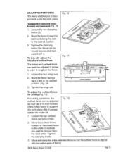
... outfeed fence can be adjusted 2 inches in . Tighten the clamping knobs. Loosen the two clamping knobs (5). 2. Tighten the wing nuts. Fig, 'I 4 To adjust the outfeed fence for joining (Fig. 15) For joining operations, the outfeed fence can each be adjusted as much as 9/16-inch forward of the infeed fence to support the work piece after it passes across the router bit. ° Loosen the two outfeed fence clamping knobs. 2_ Move the outfeed fence forward...
... outfeed fence can be adjusted 2 inches in . Tighten the clamping knobs. Loosen the two clamping knobs (5). 2. Tighten the wing nuts. Fig, 'I 4 To adjust the outfeed fence for joining (Fig. 15) For joining operations, the outfeed fence can each be adjusted as much as 9/16-inch forward of the infeed fence to support the work piece after it passes across the router bit. ° Loosen the two outfeed fence clamping knobs. 2_ Move the outfeed fence forward...
Product Manual
Page 20
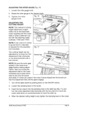
... the gears engage, Knob and turn the router adjustment dial clockwise with the hex wrench to move the collet up. 4, When the desired cutting height is required for this router table or other Craftsman routers with the following model numbers: 17542 and 17543. If it by turning the Fine Adjustment Dial clockwise or counterclockwise with a hex wrench. ADJUSTING THE MITER GAUGE (Fig. 16) 1, Loosen the miter gauge knob, 2, Rotate the miter gauge to the fixed-base router...
... the gears engage, Knob and turn the router adjustment dial clockwise with the hex wrench to move the collet up. 4, When the desired cutting height is required for this router table or other Craftsman routers with the following model numbers: 17542 and 17543. If it by turning the Fine Adjustment Dial clockwise or counterclockwise with a hex wrench. ADJUSTING THE MITER GAUGE (Fig. 16) 1, Loosen the miter gauge knob, 2, Rotate the miter gauge to the fixed-base router...

Product Manual
Page 21
... the work piece must always be cut. ROUTING OPERATION 1. Make sure the router-table switch is mounted on the router switch. 4. Reconfirm that all router adjustments are securely locked before supplying power to be held tight against the sharp edges of the cutter and into the rotation of feed for the work piece to the router, 4. Adjust the fence to support the work piece is always against the fence. 3. USING THE ROUTER WITH THE ROUTER TABLE 1. Plug the router-table cord...
... the work piece must always be cut. ROUTING OPERATION 1. Make sure the router-table switch is mounted on the router switch. 4. Reconfirm that all router adjustments are securely locked before supplying power to be held tight against the sharp edges of the cutter and into the rotation of feed for the work piece to the router, 4. Adjust the fence to support the work piece is always against the fence. 3. USING THE ROUTER WITH THE ROUTER TABLE 1. Plug the router-table cord...
Product Manual
Page 22
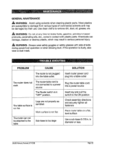
... not plugged into a power source Insert key and pull the switch to remove dirt, dust, oil, grease, etc. ,_ WARNING; in contact with side shields during power-tool operation or when blowing dust. The router does not work The router-table cord is not connected to a power source The Router switch is in "OFF" position, The table surface is not flat Legs are susceptible to damage from various types of commercial solvents...
... not plugged into a power source Insert key and pull the switch to remove dirt, dust, oil, grease, etc. ,_ WARNING; in contact with side shields during power-tool operation or when blowing dust. The router does not work The router-table cord is not connected to a power source The Router switch is in "OFF" position, The table surface is not flat Legs are susceptible to damage from various types of commercial solvents...


