Installation Manual
Page 6
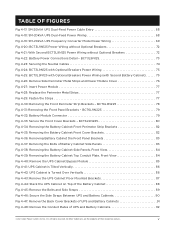
...Side Panels, Front View 84 Fig 4-39: Removing the Battery Cabinet Top Conduit Plate, Front View 84 Fig 4-40: Remove the UPS Cabinet Bypass Module 85 Fig 4-41: UPS Cabinet is Tilted Vertically 86 Fig 4-42: UPS Cabinet is Turned Over Vertically 86 Fig 4-43: Remove the UPS Cabinet Floor... owners. All other trademarks are the property of UPS and Battery Cabinets 92 ©2021 Cyber Power Systems (USA), Inc. TABLE OF FIGURES Fig 4-17: SM-20kVA UPS Dual-Feed Power Cable Entry 68 Fig 4-18: SM-20kVA UPS Dual-Feed Power Wiring 68 Fig 4-19: SM-20kVA UPS Frequency Converter Mode Power ...
...Side Panels, Front View 84 Fig 4-39: Removing the Battery Cabinet Top Conduit Plate, Front View 84 Fig 4-40: Remove the UPS Cabinet Bypass Module 85 Fig 4-41: UPS Cabinet is Tilted Vertically 86 Fig 4-42: UPS Cabinet is Turned Over Vertically 86 Fig 4-43: Remove the UPS Cabinet Floor... owners. All other trademarks are the property of UPS and Battery Cabinets 92 ©2021 Cyber Power Systems (USA), Inc. TABLE OF FIGURES Fig 4-17: SM-20kVA UPS Dual-Feed Power Cable Entry 68 Fig 4-18: SM-20kVA UPS Dual-Feed Power Wiring 68 Fig 4-19: SM-20kVA UPS Frequency Converter Mode Power ...
Installation Manual
Page 11
... high voltage component is minimized for use in this manual. Particular attention should be carried out only by user. All other trademarks are present within the battery box. Dangerous voltages are the property of protective clothing..., first aid and fire-fighting facilities. ©2021 Cyber Power Systems (USA), Inc. No risk exists to the recommendations concerning local environmental conditions and the provision of their respective owners...
... high voltage component is minimized for use in this manual. Particular attention should be carried out only by user. All other trademarks are present within the battery box. Dangerous voltages are the property of protective clothing..., first aid and fire-fighting facilities. ©2021 Cyber Power Systems (USA), Inc. No risk exists to the recommendations concerning local environmental conditions and the provision of their respective owners...
Installation Manual
Page 21
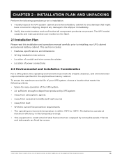
...service life of your UPS cabinet and external battery cabinet. Verify the model number and confirm that meets the following operations prior to +25°C. All other trademarks are present. The batteries operate at maximum efficiency in shipping. The top and side panels are marked on the label. 2.1 Installation...to installation: 1. All rights reserved. The UPS model, capacity and main parameters are fixed by screws. ©2021 Cyber Power Systems (USA), Inc. This section includes: • Features, specifications, and dimensions • Wiring installation instructions •...
...service life of your UPS cabinet and external battery cabinet. Verify the model number and confirm that meets the following operations prior to +25°C. All other trademarks are present. The batteries operate at maximum efficiency in shipping. The top and side panels are marked on the label. 2.1 Installation...to installation: 1. All rights reserved. The UPS model, capacity and main parameters are fixed by screws. ©2021 Cyber Power Systems (USA), Inc. This section includes: • Features, specifications, and dimensions • Wiring installation instructions •...
Installation Manual
Page 45
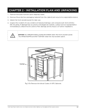
...i NOTICE The SM040KAMFA and BCT6L9N225 retain the front wooden panel. The SM020KAMFA and BCT3L9N125 retain the top wooden panel. Retain the front wooden panel for any evidence of physical damage, and compare each item with the Bill of UPS Cabinets ©2021 Cyber Power Systems (USA...of Lading. All other trademarks are evident, contact service representative immediately to determine the extent of their respective owners. 37 If damage has occurred or shortages are the property of the damage and its impact on further installation. Remove the bolts from the cabinet and recycle...
...i NOTICE The SM040KAMFA and BCT6L9N225 retain the front wooden panel. The SM020KAMFA and BCT3L9N125 retain the top wooden panel. Retain the front wooden panel for any evidence of physical damage, and compare each item with the Bill of UPS Cabinets ©2021 Cyber Power Systems (USA...of Lading. All other trademarks are evident, contact service representative immediately to determine the extent of their respective owners. 37 If damage has occurred or shortages are the property of the damage and its impact on further installation. Remove the bolts from the cabinet and recycle...
Installation Manual
Page 46
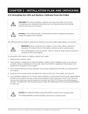
... The SM040KAMFA and BCT6L9N225 used the top wooden panel. . ©2021 Cyber Power Systems (USA), Inc. Remove the accessory pack. 2. CHAPTER 2 - Insert the forklift or pallet jack forks between the supports on the bottom of their respective owners. 38 The UPS and external battery cabinets .... (see Fig 2-12). INSTALLATION PLAN AND UNPACKING 2.5 Unloading the UPS and Battery Cabinets from pallet: 1. If installing the cabinet permanently, retain the shipping bracket and securing hardware for unloading. If the leveling feet are not fully retracted, turn all four leveling feet until ...
... The SM040KAMFA and BCT6L9N225 used the top wooden panel. . ©2021 Cyber Power Systems (USA), Inc. Remove the accessory pack. 2. CHAPTER 2 - Insert the forklift or pallet jack forks between the supports on the bottom of their respective owners. 38 The UPS and external battery cabinets .... (see Fig 2-12). INSTALLATION PLAN AND UNPACKING 2.5 Unloading the UPS and Battery Cabinets from pallet: 1. If installing the cabinet permanently, retain the shipping bracket and securing hardware for unloading. If the leveling feet are not fully retracted, turn all four leveling feet until ...
Operators Manual
Page 8
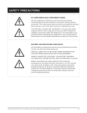
... of their respective owners. 3 WHEN CONNECTED TOGETHER, THE BATTERY TERMINAL VOLTAGE WILL EXCEED 200Vdc AND IS POTENTIALLY LETHAL. Dangerous voltages are the property of protective clothing, first aid and fire-fighting facilities. ©2021 Cyber Power Systems (USA), Inc...observed when working on, or in this manual. The components that can only be accessed by user. Battery manufacturers supply details of battery cells. SAFETY PRECAUTIONS h i NO USER-SERVICABLE COMPONENTS INSIDE All the equipment maintenance and servicing procedures involving internal access should be carried ...
... of their respective owners. 3 WHEN CONNECTED TOGETHER, THE BATTERY TERMINAL VOLTAGE WILL EXCEED 200Vdc AND IS POTENTIALLY LETHAL. Dangerous voltages are the property of protective clothing, first aid and fire-fighting facilities. ©2021 Cyber Power Systems (USA), Inc...observed when working on, or in this manual. The components that can only be accessed by user. Battery manufacturers supply details of battery cells. SAFETY PRECAUTIONS h i NO USER-SERVICABLE COMPONENTS INSIDE All the equipment maintenance and servicing procedures involving internal access should be carried ...
Operators Manual
Page 14
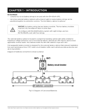
... and servicing isolation. The cabinets match the SM-UPS cabinet in a single free-standing cabinet with four strings. Hot-swappable battery module is shown as below: Fig 1-2: Diagram of batteries connection is designed for hazardous voltage protection. Diagram of Connected Batteries ©2021 Cyber Power Systems ...-rated circuit breaker within each with safety shields for the external battery cabinet that reduced installation time and maintenance time. The 2nd battery cabinet is housed in style and color. The two battery modules must put into two adjacent bays on same layer.
... and servicing isolation. The cabinets match the SM-UPS cabinet in a single free-standing cabinet with four strings. Hot-swappable battery module is shown as below: Fig 1-2: Diagram of batteries connection is designed for hazardous voltage protection. Diagram of Connected Batteries ©2021 Cyber Power Systems ...-rated circuit breaker within each with safety shields for the external battery cabinet that reduced installation time and maintenance time. The 2nd battery cabinet is housed in style and color. The two battery modules must put into two adjacent bays on same layer.
Operators Manual
Page 23
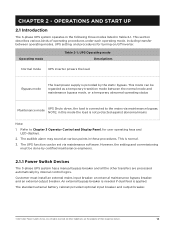
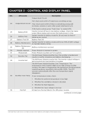
... via maintenance software. This is provided by internal control logics. Operating mode Table 2-1: UPS Operating mode Descriptions Normal mode UPS inverter powers the load Bypass mode The load power supply is normal. 3. The UPS function can be regarded as a temporary transition mode between operating modes, UPS setting, and procedures for user operating keys and LED displays. 2. However, the setting and commissioning must install an external...
... via maintenance software. This is provided by internal control logics. Operating mode Table 2-1: UPS Operating mode Descriptions Normal mode UPS inverter powers the load Bypass mode The load power supply is normal. 3. The UPS function can be regarded as a temporary transition mode between operating modes, UPS setting, and procedures for user operating keys and LED displays. 2. However, the setting and commissioning must install an external...
Operators Manual
Page 29
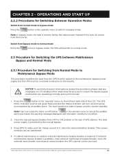
... in bypass mode, the UPS will be serviced. ©2021 Cyber Power Systems (USA), Inc. The UPS Mimic indicator Inverter will green flash and also the Status Indicator will turn red and will transfer to normal mode 2.3 Procedure for Switching the UPS between Maintenance Bypass and Normal Mode 2.3.1 Procedure for Switching Between Operation Modes Switch from bypass mode to ensure the bypass supply...
... in bypass mode, the UPS will be serviced. ©2021 Cyber Power Systems (USA), Inc. The UPS Mimic indicator Inverter will green flash and also the Status Indicator will turn red and will transfer to normal mode 2.3 Procedure for Switching the UPS between Maintenance Bypass and Normal Mode 2.3.1 Procedure for Switching Between Operation Modes Switch from bypass mode to ensure the bypass supply...
Operators Manual
Page 43
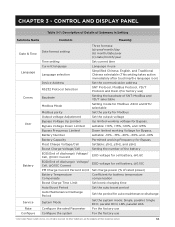
... use For the factory use ©2021 Cyber Power Systems (USA), Inc. CHAPTER 3 - User Battery Service Rate Configure Date format setting Time setting Current language Language selection Device Address RS232 Protocol Selection Baudrate Modbus Mode Modbus parity Output voltage Adjustment Bypass Voltage Up Limited Bypass Voltage Down Limited Bypass Frequency Limited Battery Number Battery Capacity Float Charge Voltage/Cell Boost Charge Voltage...
... use For the factory use ©2021 Cyber Power Systems (USA), Inc. CHAPTER 3 - User Battery Service Rate Configure Date format setting Time setting Current language Language selection Device Address RS232 Protocol Selection Baudrate Modbus Mode Modbus parity Output voltage Adjustment Bypass Voltage Up Limited Bypass Voltage Down Limited Bypass Frequency Limited Battery Number Battery Capacity Float Charge Voltage/Cell Boost Charge Voltage...
Operators Manual
Page 45
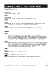
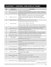
... owners. 40 Stop battery test or battery maintenance. UPS transfers to normal mode after replacing new batteries. Make sure that there are the property of float voltage. All other trademarks are not any current warnings or alarms, make sure that battery voltage is normal, the UPS will trigger an alarm and transfer back to normal mode or transfer to inverter mode manually. Command Battery test...
... owners. 40 Stop battery test or battery maintenance. UPS transfers to normal mode after replacing new batteries. Make sure that there are the property of float voltage. All other trademarks are not any current warnings or alarms, make sure that battery voltage is normal, the UPS will trigger an alarm and transfer back to normal mode or transfer to inverter mode manually. Command Battery test...
Operators Manual
Page 49
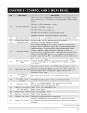
... Rectifier Over Temperature. This alarm is faulted and results in the rectifier IGBTs. Whether the ventilation channel is too high. 2. Check the mains power failure status and recover the mains power in time 26 Battery Test System transfer to battery mode for 20 seconds to check if batteries are the property of EOD voltage to bypass. Whether the input...
... Rectifier Over Temperature. This alarm is faulted and results in the rectifier IGBTs. Whether the ventilation channel is too high. 2. Check the mains power failure status and recover the mains power in time 26 Battery Test System transfer to battery mode for 20 seconds to check if batteries are the property of EOD voltage to bypass. Whether the input...
Operators Manual
Page 51
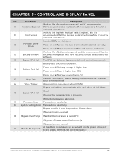
...Bypass Fan Fail At least one or more parallel cables are connected not correctly. All other modules, if yes, please adjust inverter voltage of discharging) 54 Battery Test Fail Battery Test Fail. There is no X redundant powers module in float charge mode. 50 UPS Locked Forbidden to supply after the battery is inhibited to shutdown UPS power module manually...this command enable UPS to transfer to bypass manually" command. Parallel cables error. Check 55 Battery Maintenance If UPS is normal and not any alarms Fail If the battery voltage is over 90% of float ...
...Bypass Fan Fail At least one or more parallel cables are connected not correctly. All other modules, if yes, please adjust inverter voltage of discharging) 54 Battery Test Fail Battery Test Fail. There is no X redundant powers module in float charge mode. 50 UPS Locked Forbidden to supply after the battery is inhibited to shutdown UPS power module manually...this command enable UPS to transfer to bypass manually" command. Parallel cables error. Check 55 Battery Maintenance If UPS is normal and not any alarms Fail If the battery voltage is over 90% of float ...
Operators Manual
Page 53
...battery history data. 83 Byp Fan Time Reset Reset timing of their respective owners. 48 continued on next page ©2021 Cyber Power Systems (USA), Inc. It's optional. It must be confirmed that sleeping power modules are shorted and cannot be standby in intelligent sleep mode. Inlet air is abnormal UPS works in turn...current timeout and UPS transfer to battery mode. 76 Input Over Curr Tout Please check if input voltage is too low and output load is not sure. 75 Manual Transfer to INV Manually transfer UPS to inverter when bypass is over track. Sensor Outlet ...
...battery history data. 83 Byp Fan Time Reset Reset timing of their respective owners. 48 continued on next page ©2021 Cyber Power Systems (USA), Inc. It's optional. It must be confirmed that sleeping power modules are shorted and cannot be standby in intelligent sleep mode. Inlet air is abnormal UPS works in turn...current timeout and UPS transfer to battery mode. 76 Input Over Curr Tout Please check if input voltage is too low and output load is not sure. 75 Manual Transfer to INV Manually transfer UPS to inverter when bypass is over track. Sensor Outlet ...
Operators Manual
Page 54
... OK 93 Stop Test Manually stop battery test or battery maintenance, UPS transfer back to normal mode. 94 Wave Trigger Waveform has been saved while UPS fail Bypass and cabinet communicate with new batteries. If monitoring board is abnormal. All other via software. Inverter IGBTs are shutdown. 88 INV IGBT Driver Block Please check if power modules are set as same ID...
... OK 93 Stop Test Manually stop battery test or battery maintenance, UPS transfer back to normal mode. 94 Wave Trigger Waveform has been saved while UPS fail Bypass and cabinet communicate with new batteries. If monitoring board is abnormal. All other via software. Inverter IGBTs are shutdown. 88 INV IGBT Driver Block Please check if power modules are set as same ID...
Warranty Statement
Page 1
...specific legal rights and you may impose additional obligations, or additional "implied warranties." This Warranty is unable to or decides not to repair or replace the Product (if defective) within a reasonable time, CyberPower will refund to you the full purchase price you paid for it at www.cyberpowersystems.com/support... to as outlined in the installation, user and service manuals will follow the instructions as the "Warranty"). The Product must provide a copy of your purchase, you will need to the limitations and exclusions set forth in this informal mechanism shall...
...specific legal rights and you may impose additional obligations, or additional "implied warranties." This Warranty is unable to or decides not to repair or replace the Product (if defective) within a reasonable time, CyberPower will refund to you the full purchase price you paid for it at www.cyberpowersystems.com/support... to as outlined in the installation, user and service manuals will follow the instructions as the "Warranty"). The Product must provide a copy of your purchase, you will need to the limitations and exclusions set forth in this informal mechanism shall...
Warranty Statement
Page 2
... environment and in storage, nor if there has been improper installation, operation or maintenance, or for use with the Product. See manuals provided and also available to repair, replace, or refund the Product (at CyberPower's option, the repair or replacement services described herein. This Product is to download at the sole expense of the Product or the Connected Equipment...
... environment and in storage, nor if there has been improper installation, operation or maintenance, or for use with the Product. See manuals provided and also available to repair, replace, or refund the Product (at CyberPower's option, the repair or replacement services described herein. This Product is to download at the sole expense of the Product or the Connected Equipment...
Statement of Work
Page 1
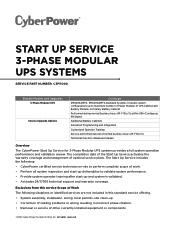
.... All rights reserved START UP SERVICE 3-PHASE MODULAR UPS SYSTEMS SERVICE PART NUMBER: C3P11000 Eligible Models and Upgrades 3-Phase Modular UPS Service Upgrade Options Coverage SM020KAMFA, SM040KAMFA Standard Systems. Includes system configurations up to maximum number of Power Modules in UPS Cabinet and Battery Modules in incorrect phase rotation. • Removal or service of other currently installed equipment or components ©2021...
.... All rights reserved START UP SERVICE 3-PHASE MODULAR UPS SYSTEMS SERVICE PART NUMBER: C3P11000 Eligible Models and Upgrades 3-Phase Modular UPS Service Upgrade Options Coverage SM020KAMFA, SM040KAMFA Standard Systems. Includes system configurations up to maximum number of Power Modules in UPS Cabinet and Battery Modules in incorrect phase rotation. • Removal or service of other currently installed equipment or components ©2021...
Datasheet
Page 1
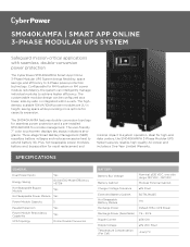
.... Configurable for remote management. The SM040KAMFA features double-conversion topology for seamless power protection and a pre-installed RMCARD205 for N+N system or N+1 power module redundancy, the system can be configured as a tower, side-by-side, or integrated within a rack. SPECIFICATIONS GENERAL Dual Power Inputs Yes Energy Saving Hot Swappable Bypass Module Online ECO Mode Efficiency >97.5% Yes Hot Swappable...
.... Configurable for remote management. The SM040KAMFA features double-conversion topology for seamless power protection and a pre-installed RMCARD205 for N+N system or N+1 power module redundancy, the system can be configured as a tower, side-by-side, or integrated within a rack. SPECIFICATIONS GENERAL Dual Power Inputs Yes Energy Saving Hot Swappable Bypass Module Online ECO Mode Efficiency >97.5% Yes Hot Swappable...
Datasheet
Page 3
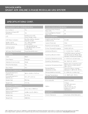
...respective owners. www.cyberpowersystems.com MANAGEMENT AND COMMUNICATIONS Dry Contacts Emergency Power Off (EPO) Port LCD LED Status Indicators SNMP / HTTP Remote Monitoring Communication Port/Protocols Software (Free Download) Yes Yes Multifunction LCD, Touch Screen, Color Rectifier, Battery, Bypass, Inverter..., CSA C22.2, No. 107.3-14 CFR 47 FCC Part 15, Subpart B, Class A IEC62040-2 Product Warranty One-Year Limited Warranty ©2021 Cyber Power Systems (USA), Inc. CyberPower reserves the right to change, without notice, marketing programs, product offerings and specifications.
...respective owners. www.cyberpowersystems.com MANAGEMENT AND COMMUNICATIONS Dry Contacts Emergency Power Off (EPO) Port LCD LED Status Indicators SNMP / HTTP Remote Monitoring Communication Port/Protocols Software (Free Download) Yes Yes Multifunction LCD, Touch Screen, Color Rectifier, Battery, Bypass, Inverter..., CSA C22.2, No. 107.3-14 CFR 47 FCC Part 15, Subpart B, Class A IEC62040-2 Product Warranty One-Year Limited Warranty ©2021 Cyber Power Systems (USA), Inc. CyberPower reserves the right to change, without notice, marketing programs, product offerings and specifications.