Owners Manual
Page 3
... and reassembly...8 Recommended tools...8 microSD card...8 Removing microSD card...8 Installing microSD card...8 Base cover...8 Removing base cover...8 Installing base cover...10 Battery...10 Lithium-ion battery precautions...10 Removing battery - optional...10 Installing battery...11 Keyboard lattice and Keyboard...11 Removing keyboard...11 Installing keyboard...12 Solid State Drive - optional ...13 Removing M.2 Solid State Drive (SSD)...13...
... and reassembly...8 Recommended tools...8 microSD card...8 Removing microSD card...8 Installing microSD card...8 Base cover...8 Removing base cover...8 Installing base cover...10 Battery...10 Lithium-ion battery precautions...10 Removing battery - optional...10 Installing battery...11 Keyboard lattice and Keyboard...11 Removing keyboard...11 Installing keyboard...12 Solid State Drive - optional ...13 Removing M.2 Solid State Drive (SSD)...13...
Owners Manual
Page 11
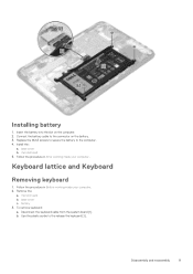
... on the battery. 3. Install the: a. battery 3. To remove keyboard: a. b. Keyboard lattice and Keyboard Removing keyboard 1. Use the plastic scribe to the computer. 4. base cover b. Installing battery 1. Disassembly and reassembly 11 Replace the M2x3 screws to secure the battery to the release the keyboard [2]. microSD card 5. Disconnect the keyboard cable from the system board [1]. Connect the battery cable...
... on the battery. 3. Install the: a. battery 3. To remove keyboard: a. b. Keyboard lattice and Keyboard Removing keyboard 1. Use the plastic scribe to the computer. 4. base cover b. Installing battery 1. Disassembly and reassembly 11 Replace the M2x3 screws to secure the battery to the release the keyboard [2]. microSD card 5. Disconnect the keyboard cable from the system board [1]. Connect the battery cable...
Owners Manual
Page 13
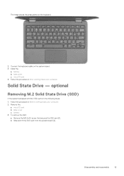
Connect the keyboard cable on the keyboard. 2. Solid State Drive - microSD card b. base cover c. Slide and lift the SSD card from the system board [2]. Install the: a. microSD card 4. optional Removing M.2 Solid State Drive (SSD) If the system is shipped ... that secures the SSD card [1]. The image shows the press points on the system board. 3. Follow the procedure in Before working inside your computer. base cover c.
Connect the keyboard cable on the keyboard. 2. Solid State Drive - microSD card b. base cover c. Slide and lift the SSD card from the system board [2]. Install the: a. microSD card 4. optional Removing M.2 Solid State Drive (SSD) If the system is shipped ... that secures the SSD card [1]. The image shows the press points on the system board. 3. Follow the procedure in Before working inside your computer. base cover c.

Owners Manual
Page 19
...Before working inside your computer. touch pad cable [3] 4. Disassembly and reassembly 19 System board Removing system board 1. audio cable [1] b. b. 5. Install the: a. base cover c. keyboard cable [2] c. microSD card 6. Remove the: a. SSD card 3. Disconnect the following cables: a. Disconnect coin cell battery , power connector port, and speaker cable [1, 2, 3].... that secure on the system board [4, 5]. Follow the procedure in After working inside your computer. 2. microSD card b. base cover c. To disconnect the cable: a. battery b. battery d.
...Before working inside your computer. touch pad cable [3] 4. Disassembly and reassembly 19 System board Removing system board 1. audio cable [1] b. b. 5. Install the: a. base cover c. keyboard cable [2] c. microSD card 6. Remove the: a. SSD card 3. Disconnect the following cables: a. Disconnect coin cell battery , power connector port, and speaker cable [1, 2, 3].... that secure on the system board [4, 5]. Follow the procedure in After working inside your computer. 2. microSD card b. base cover c. To disconnect the cable: a. battery b. battery d.
Owners Manual
Page 21
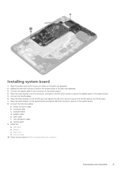
Replace the M2.0x3.0 screws to secure the system board to the system board. 5. keyboard cable d. coin cell battery cable g. Disassembly and reassembly 21 Place the metal bracket over the connector, and tighten the M2.0x3.0 screws to secure ... the metal bracket on the system board and tighten M2.0x3.0 screws to the connector on the palm rest assembly. 2. Install the: a. speaker cable e. base cover d. Connect the following cables: a. SSD card b. battery c. Connect the display cable to secure on the WLAN card. 7. power connector cable b. Align the system board...
Replace the M2.0x3.0 screws to secure the system board to the system board. 5. keyboard cable d. coin cell battery cable g. Disassembly and reassembly 21 Place the metal bracket over the connector, and tighten the M2.0x3.0 screws to secure ... the metal bracket on the system board and tighten M2.0x3.0 screws to the connector on the palm rest assembly. 2. Install the: a. speaker cable e. base cover d. Connect the following cables: a. SSD card b. battery c. Connect the display cable to secure on the WLAN card. 7. power connector cable b. Align the system board...
Owners Manual
Page 31
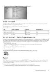
...the existing USB 2.0 bus (refer to the picture below). It dramatically simplified the connection between host computers and peripheral devices like mice, keyboards, external drivers, and printers. USB evolution Type Data Transfer Rate USB 2.0 480 Mbps Category High Speed Introduction Year 2000 USB 3.0/USB 3.1... • New power management features • Full-duplex data transfers and support for more speed grows by the technical changes below cover some of 4.8Gbps. Technology and components 31 Table 1. USB 3.0/USB 3.1 Gen 1 achieves the much higher performance by ever faster...
...the existing USB 2.0 bus (refer to the picture below). It dramatically simplified the connection between host computers and peripheral devices like mice, keyboards, external drivers, and printers. USB evolution Type Data Transfer Rate USB 2.0 480 Mbps Category High Speed Introduction Year 2000 USB 3.0/USB 3.1... • New power management features • Full-duplex data transfers and support for more speed grows by the technical changes below cover some of 4.8Gbps. Technology and components 31 Table 1. USB 3.0/USB 3.1 Gen 1 achieves the much higher performance by ever faster...


