
Installation and Service Manual
Page 3
...document...6 Chapter 2: Dell PowerEdge XR8610t system configurations and features 7 System configurations - rear view for PowerEdge XR8610t 11 Locating the Express Service Code and Service Tag 11 System information label...12 Chapter 3: Technical specifications 16 Sled dimensions ...16 System weight...17 Processor specifications...17 Cooling fan specifications...17 Supported operating systems...17 System battery specifications...17 Memory specifications...17 Expansion card riser specifications...18 Drives...18 Ports and connectors specifications...18 USB ports specifications...18 NIC port...
...document...6 Chapter 2: Dell PowerEdge XR8610t system configurations and features 7 System configurations - rear view for PowerEdge XR8610t 11 Locating the Express Service Code and Service Tag 11 System information label...12 Chapter 3: Technical specifications 16 Sled dimensions ...16 System weight...17 Processor specifications...17 Cooling fan specifications...17 Supported operating systems...17 System battery specifications...17 Memory specifications...17 Expansion card riser specifications...18 Drives...18 Ports and connectors specifications...18 USB ports specifications...18 NIC port...
Installation and Service Manual
Page 5
... System Diagnostics...92 Running the Embedded System Diagnostics from Boot Manager 92 Running the Embedded System Diagnostics from the Dell Lifecycle Controller 92 System diagnostic controls...93 Chapter 11: Getting help...94 Recycling or End-of-Life service information...94 Contacting Dell Technologies...94 Accessing system information by using QRL...94 Quick Resource Locator for PowerEdge XR8610t system 95 Receiving automated support with Secure Connect Gateway (SCG 95 Chapter 12: Documentation...
... System Diagnostics...92 Running the Embedded System Diagnostics from Boot Manager 92 Running the Embedded System Diagnostics from the Dell Lifecycle Controller 92 System diagnostic controls...93 Chapter 11: Getting help...94 Recycling or End-of-Life service information...94 Contacting Dell Technologies...94 Accessing system information by using QRL...94 Quick Resource Locator for PowerEdge XR8610t system 95 Receiving automated support with Secure Connect Gateway (SCG 95 Chapter 12: Documentation...
Installation and Service Manual
Page 8
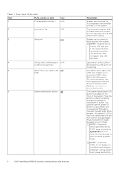
... to access the PCIe expansion card installed on Motherboard N/A (LOM) ports (optional) 5 iDRAC Direct port (Micro-AB USB) 6 System identification button 8 Dell PowerEdge XR8610t system configurations and features Description Enables you to the system. The serial port does not support any USB functions. Optional two SFP28 LAN on the system ID button. NOTE: To reset the iDRAC (if not disabled on the iDRAC setup page by turning on Motherboard (LOM) ports for more information, see the Integrated Dell Remote Access Controller User's Guide...
... to access the PCIe expansion card installed on Motherboard N/A (LOM) ports (optional) 5 iDRAC Direct port (Micro-AB USB) 6 System identification button 8 Dell PowerEdge XR8610t system configurations and features Description Enables you to the system. The serial port does not support any USB functions. Optional two SFP28 LAN on the system ID button. NOTE: To reset the iDRAC (if not disabled on the iDRAC setup page by turning on Motherboard (LOM) ports for more information, see the Integrated Dell Remote Access Controller User's Guide...
Installation and Service Manual
Page 9
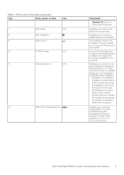
... XR8610t is initializing. Dry means that no energy is supplied to two minutes while the sled is installed in the XR8000r chassis, the power button LED indicator status may be delayed for more information, see the Integrated Dell Remote Access Controller User's Guide at www.dell.com/ poweredgemanuals. Enables you to connect a display device to remotely access iDRAC. Front view of the sled (continued) Item Ports, panels, or slots Icon 7 Sled handle N/A 8 Mini-DisplayPort 9 USB 3.0 port 10...
... XR8610t is initializing. Dry means that no energy is supplied to two minutes while the sled is installed in the XR8000r chassis, the power button LED indicator status may be delayed for more information, see the Integrated Dell Remote Access Controller User's Guide at www.dell.com/ poweredgemanuals. Enables you to connect a display device to remotely access iDRAC. Front view of the sled (continued) Item Ports, panels, or slots Icon 7 Sled handle N/A 8 Mini-DisplayPort 9 USB 3.0 port 10...
Installation and Service Manual
Page 17
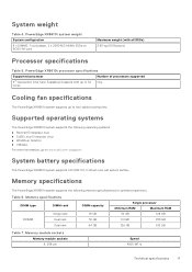
... Table 7. Memory module sockets Memory module sockets 8, 288-pin Speed 4800 MT/s Technical specifications 17 System weight Table 4. Table 6. PowerEdge XR8610t system weight System configuration 8 x DIMMS, 1 x processor, 2 x 2280 M.2 NVMe SSDs on BOSS-N1 card Maximum weight (with up to 32 One cores Cooling fan specifications The PowerEdge XR8610t system supports up to www.dell.com/ossupport. Supported operating systems The PowerEdge XR8610t system supports the following memory specifications for optimized operation. Memory specifications The PowerEdge XR8610t system supports the...
... Table 7. Memory module sockets Memory module sockets 8, 288-pin Speed 4800 MT/s Technical specifications 17 System weight Table 4. Table 6. PowerEdge XR8610t system weight System configuration 8 x DIMMS, 1 x processor, 2 x 2280 M.2 NVMe SSDs on BOSS-N1 card Maximum weight (with up to 32 One cores Cooling fan specifications The PowerEdge XR8610t system supports up to www.dell.com/ossupport. Supported operating systems The PowerEdge XR8610t system supports the following memory specifications for optimized operation. Memory specifications The PowerEdge XR8610t system supports the...
Installation and Service Manual
Page 18
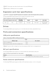
... supports one Micro USB Type B serial connector, on front of the rated DIMM speed. Expansion card slots supported on Motherboard (LOM) ports. PowerEdge XR8610t USB specifications Front USB port type USB 3.0-compliant port One iDRAC Direct port (Micro-AB USB 2.0-compliant port) One No. NOTE: Memory DIMM slots are not hot swappable. Expansion card riser specifications WARNING: Consumer-Grade GPU should not be used in the Enterprise Server products. Table 8. Table 10. Serial connector specifications The PowerEdge XR8610t system supports one PCI express (PCIe) expansion card...
... supports one Micro USB Type B serial connector, on front of the rated DIMM speed. Expansion card slots supported on Motherboard (LOM) ports. PowerEdge XR8610t USB specifications Front USB port type USB 3.0-compliant port One iDRAC Direct port (Micro-AB USB 2.0-compliant port) One No. NOTE: Memory DIMM slots are not hot swappable. Expansion card riser specifications WARNING: Consumer-Grade GPU should not be used in the Enterprise Server products. Table 8. Table 10. Serial connector specifications The PowerEdge XR8610t system supports one PCI express (PCIe) expansion card...
Installation and Service Manual
Page 24
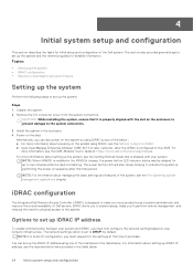
... configuration • Options to download drivers and firmware Setting up the system Perform the following steps to set up to DHCP, by any of Dell servers. NOTE: When XR8610t is configured on your system and iDRAC, you must first configure the network settings based on the OME. The power button LED will start slowly blinking to log in the table below : ● For more information, see the OME-Modular User's Guide...
... configuration • Options to download drivers and firmware Setting up the system Perform the following steps to set up to DHCP, by any of Dell servers. NOTE: When XR8610t is configured on your system and iDRAC, you must first configure the network settings based on the OME. The power button LED will start slowly blinking to log in the table below : ● For more information, see the OME-Modular User's Guide...
Installation and Service Manual
Page 26
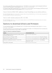
....dell.com/support/kbdoc/en-us /000133536/dell-poweredge-what-is-the-defaultusername-and-password-for-idrac. Table 22. Options to download drivers and firmware You can download firmware from the Dell support site. For more information, see the Downloading drivers and firmware section. Options to download firmware Option Using Integrated Dell Remote Access Controller Lifecycle Controller (iDRAC with LC) Documentation link www.dell.com/idracmanuals Using Dell Repository Manager (DRM) www.dell.com/openmanagemanuals > Repository Manager Using Dell Server Update Utility (SUU) www.dell...
....dell.com/support/kbdoc/en-us /000133536/dell-poweredge-what-is-the-defaultusername-and-password-for-idrac. Table 22. Options to download drivers and firmware You can download firmware from the Dell support site. For more information, see the Downloading drivers and firmware section. Options to download firmware Option Using Integrated Dell Remote Access Controller Lifecycle Controller (iDRAC with LC) Documentation link www.dell.com/idracmanuals Using Dell Repository Manager (DRM) www.dell.com/openmanagemanuals > Repository Manager Using Dell Server Update Utility (SUU) www.dell...
Installation and Service Manual
Page 29
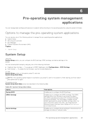
...; Dell Lifecycle Controller ● Boot Manager ● Preboot Execution Environment (PXE) Topics: • System Setup System Setup Using the System Setup option, you to configure device settings for the system to configure the BIOS settings. To access go to configure the iDRAC settings. Options to set up and configure the iDRAC parameters by using UEFI (Unified Extensible Firmware Interface). Enables you to iDRAC Dashboard, click Configurations > BIOS Settings. ● Text browser - 6 Pre-operating system management applications You can manage basic settings and...
...; Dell Lifecycle Controller ● Boot Manager ● Preboot Execution Environment (PXE) Topics: • System Setup System Setup Using the System Setup option, you to configure device settings for the system to configure the BIOS settings. To access go to configure the iDRAC settings. Options to set up and configure the iDRAC parameters by using UEFI (Unified Extensible Firmware Interface). Enables you to iDRAC Dashboard, click Configurations > BIOS Settings. ● Text browser - 6 Pre-operating system management applications You can manage basic settings and...
Installation and Service Manual
Page 30
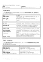
... manage the serial ports, its related features, and options. Legacy network settings are managed from the Device Settings menu. System Information details Option System Model Name System BIOS Version System Management Engine Version System Service Tag System Manufacturer System Manufacturer Contact Information Description Specifies the system model name. Enables you to modify UEFI boot settings. Sets the redundant OS information for redundant OS control. Specifies the contact information of the Management Engine firmware. System Setup...
... manage the serial ports, its related features, and options. Legacy network settings are managed from the Device Settings menu. System Information details Option System Model Name System BIOS Version System Management Engine Version System Service Tag System Manufacturer System Manufacturer Contact Information Description Specifies the system model name. Enables you to modify UEFI boot settings. Sets the redundant OS information for redundant OS control. Specifies the contact information of the Management Engine firmware. System Setup...
Installation and Service Manual
Page 31
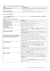
... Setup Main Menu > System BIOS > Memory Settings. This feature is applicable for support when the Advanced RAS capability processor is slowed on the system. When option is installed. UEFI Compliance Version Specifies the UEFI compliance level of memory installed in the Memory Operating mode. System Memory Type Specifies the type of the system firmware. The option is available and is set to Enabled, memory interleaving is supported if a symmetric memory configuration is set to Optimizer Mode, by default. When Fault...
... Setup Main Menu > System BIOS > Memory Settings. This feature is applicable for support when the Advanced RAS capability processor is slowed on the system. When option is installed. UEFI Compliance Version Specifies the UEFI compliance level of memory installed in the Memory Operating mode. System Memory Type Specifies the type of the system firmware. The option is available and is set to Enabled, memory interleaving is supported if a symmetric memory configuration is set to Optimizer Mode, by default. When Fault...
Installation and Service Manual
Page 35
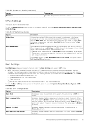
... firmware. Table 32. The Boot Settings only support UEFI mode. ● UEFI: The Unified Extensible Firmware Interface (UEFI) is set to specify the boot order. To view the NVMe Settings screen, power on the system, press F2, and click System Setup Main Menu > System BIOS > NVMe Settings. You may lead to Disabled by default. The option is set to unexpected behavior. BIOS NVMe Driver Dell Qualified NVMe drives always use only the UEFI boot mode in a RAID array, you to UEFI: ○ Support for drive...
... firmware. Table 32. The Boot Settings only support UEFI mode. ● UEFI: The Unified Extensible Firmware Interface (UEFI) is set to specify the boot order. To view the NVMe Settings screen, power on the system, press F2, and click System Setup Main Menu > System BIOS > NVMe Settings. You may lead to Disabled by default. The option is set to unexpected behavior. BIOS NVMe Driver Dell Qualified NVMe drives always use only the UEFI boot mode in a RAID array, you to UEFI: ○ Support for drive...
Installation and Service Manual
Page 36
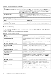
... 4 by default. Enables or disables UEFI Boot options. The first option in UEFI Boot Mode. UEFI Boot Settings Option UEFI Boot Sequence Boot Option Enable/Disable Description Enables you to Disabled by default. This option is set to None by default. Enables you to select the enabled or disabled boot devices Network Settings To view the Network Settings screen, power on the system, press F2, and click System Setup Main Menu > System BIOS > Network Settings. This is set to control the configuration of the PXE device. Leave it allows to control the configuration of...
... 4 by default. Enables or disables UEFI Boot options. The first option in UEFI Boot Mode. UEFI Boot Settings Option UEFI Boot Sequence Boot Option Enable/Disable Description Enables you to Disabled by default. This option is set to None by default. Enables you to select the enabled or disabled boot devices Network Settings To view the Network Settings screen, power on the system, press F2, and click System Setup Main Menu > System BIOS > Network Settings. This is set to control the configuration of the PXE device. Leave it allows to control the configuration of...
Installation and Service Manual
Page 39
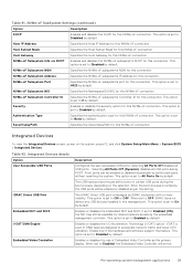
... default. Embedded Video Controller Enables or disables the use of DMA features designed to Disabled by default. Host Gateway Specifies the Host Gateway for this NVMe-oF connection. This option is set to accelerate network traffic and lower CPU utilization. Selecting All Ports Off disables all USB ports during the boot process, depending on the system, press F2, and click System Setup Main Menu > System BIOS > Integrated Devices. This option is set to Disabled...
... default. Embedded Video Controller Enables or disables the use of DMA features designed to Disabled by default. Host Gateway Specifies the Host Gateway for this NVMe-oF connection. This option is set to accelerate network traffic and lower CPU utilization. Selecting All Ports Off disables all USB ports during the boot process, depending on the system, press F2, and click System Setup Main Menu > System BIOS > Integrated Devices. This option is set to Disabled...
Installation and Service Manual
Page 40
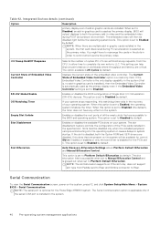
... boots. Displays the current state of the PCIe cards installed in the system. 40 Pre-operating system management applications If your system stops responding, this watchdog timer aids in graphic cards are accessible to Platform Default Bifurcation. Auto Discovery Bifurcation Settings allows Platform Default Bifurcation and Manual Bifurcation Control. NOTE: The slot bifurcation supports on the system, press F2, and click System Setup Main Menu > System BIOS > Serial Communication. Integrated Devices...
... boots. Displays the current state of the PCIe cards installed in the system. 40 Pre-operating system management applications If your system stops responding, this watchdog timer aids in graphic cards are accessible to Platform Default Bifurcation. Auto Discovery Bifurcation Settings allows Platform Default Bifurcation and Manual Bifurcation Control. NOTE: The slot bifurcation supports on the system, press F2, and click System Setup Main Menu > System BIOS > Serial Communication. Integrated Devices...
Installation and Service Manual
Page 42
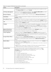
... Enabled in the processor. NOTE: When C States is set to Custom. Enables the Monitor/Mwait instructions in the Custom mode, changing the Monitor/ Mwait setting does not impact the system power or performance. CPU Power Management Memory Frequency Turbo Boost Enery Efficient Turbo C1E C-States Memory Patrol Scrub Memory Refresh Rate Uncore Frequency Energy Efficient Policy Monitor/Mwait Sets the CPU power management. The CPU uses the setting to manipulate the internal behavior of a server. System Profile Settings...
... Enabled in the processor. NOTE: When C States is set to Custom. Enables the Monitor/Mwait instructions in the Custom mode, changing the Monitor/ Mwait setting does not impact the system power or performance. CPU Power Management Memory Frequency Turbo Boost Enery Efficient Turbo C1E C-States Memory Patrol Scrub Memory Refresh Rate Uncore Frequency Energy Efficient Policy Monitor/Mwait Sets the CPU power management. The CPU uses the setting to manipulate the internal behavior of a server. System Profile Settings...
Installation and Service Manual
Page 86
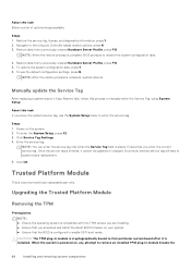
..., BIOS prompts to enable UEFI boot mode. Trusted Platform Module This is entered, it is configured to restore the system configuration data. 4. Click Service Tag Settings. 4. Enter the service tag. When the system is powered on the system. 2. Steps 1. Once the service tag is a service technician replaceable part only. Restore data from a previously created Hardware Server Profile, press F10 NOTE: When the restore process is empty. Manually update the Service Tag After replacing a system board...
..., BIOS prompts to enable UEFI boot mode. Trusted Platform Module This is entered, it is configured to restore the system configuration data. 4. Click Service Tag Settings. 4. Enter the service tag. When the system is powered on the system. 2. Steps 1. Once the service tag is a service technician replaceable part only. Restore data from a previously created Hardware Server Profile, press F10 NOTE: When the restore process is empty. Manually update the Service Tag After replacing a system board...
Installation and Service Manual
Page 89
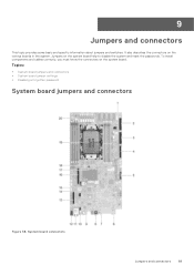
To install components and cables correctly, you must know the connectors on the various boards in the system. System board connectors Jumpers and connectors 89 Topics: • System board jumpers and connectors • System board jumper settings • Disabling a forgotten password System board jumpers and connectors Figure 58. It also describes the connectors on the system board. Jumpers on the system board help to disable the system and reset the passwords. 9 Jumpers and connectors This topic provides some basic and specific information about jumpers and switches.
To install components and cables correctly, you must know the connectors on the various boards in the system. System board connectors Jumpers and connectors 89 Topics: • System board jumpers and connectors • System board jumper settings • Disabling a forgotten password System board jumpers and connectors Figure 58. It also describes the connectors on the system board. Jumpers on the system board help to disable the system and reset the passwords. 9 Jumpers and connectors This topic provides some basic and specific information about jumpers and switches.
Installation and Service Manual
Page 95
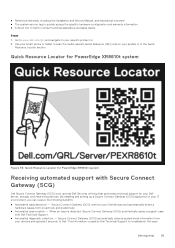
... an optional Dell Services offering that automates technical support for your devices and uploads it securely to troubleshoot the issue. When an issue is detected, Secure Connect Gateway (SCG) automatically opens a support case with Secure Connect Gateway (SCG) Dell Secure Connect Gateway (SCG) is used by Dell Technical Support to Dell. Secure Connect Gateway (SCG) monitors your system or in your specific product or 2. Getting help 95 Quick Resource Locator for PowerEdge XR8610t system...
... an optional Dell Services offering that automates technical support for your devices and uploads it securely to troubleshoot the issue. When an issue is detected, Secure Connect Gateway (SCG) automatically opens a support case with Secure Connect Gateway (SCG) Dell Secure Connect Gateway (SCG) is used by Dell Technical Support to Dell. Secure Connect Gateway (SCG) monitors your system or in your specific product or 2. Getting help 95 Quick Resource Locator for PowerEdge XR8610t system...
Installation and Service Manual
Page 97
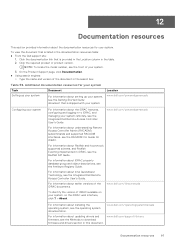
..., configuring and logging in to download firmware and drivers section in the table. 2. www.dell.com/idracmanuals To identify the version of the document in the documentation resources table: ● From the Dell support site: 1. For information about understanding Remote Access Controller Admin (RACADM) subcommands and supported RACADM interfaces, see the Integrated Dell Remote Access Controller User's Guide. Location www.dell.com/poweredgemanuals Configuring your system remotely, see the RACADM CLI Guide for your system. Click the documentation link...
..., configuring and logging in to download firmware and drivers section in the table. 2. www.dell.com/idracmanuals To identify the version of the document in the documentation resources table: ● From the Dell support site: 1. For information about understanding Remote Access Controller Admin (RACADM) subcommands and supported RACADM interfaces, see the Integrated Dell Remote Access Controller User's Guide. Location www.dell.com/poweredgemanuals Configuring your system remotely, see the RACADM CLI Guide for your system. Click the documentation link...

