

Owner's Manual (PDF)
Page 4
...-Board Shield 31 Prerequisites 31 Procedure 31 11 Replacing the System-Board Shield 33 Procedure 33 Postrequisites 33 12 Removing the Power-Supply Unit 35 Prerequisites 35 Procedure 35 13 Replacing the Power-Supply Unit 37 Procedure 37 Postrequisites 37 14 Removing the Memory Module(s 39 Prerequisites 39 Procedure 39 15 Replacing the Memory...
...-Board Shield 31 Prerequisites 31 Procedure 31 11 Replacing the System-Board Shield 33 Procedure 33 Postrequisites 33 12 Removing the Power-Supply Unit 35 Prerequisites 35 Procedure 35 13 Replacing the Power-Supply Unit 37 Procedure 37 Postrequisites 37 14 Removing the Memory Module(s 39 Prerequisites 39 Procedure 39 15 Replacing the Memory...
Owner's Manual (PDF)
Page 5
...-Drive Cage 55 Prerequisites 55 Procedure 55 23 Replacing the Hard-Drive Cage 57 Procedure 57 Postrequisites 57 24 Removing the Power-Supply Fan 59 Prerequisites 59 Procedure 59 25 Replacing the Power-Supply Fan 61 Procedure 61 Postrequisites 61 26 Removing the TV-Tuner Mini-Card 63 Prerequisites 63 Procedure 63 27 Replacing...
...-Drive Cage 55 Prerequisites 55 Procedure 55 23 Replacing the Hard-Drive Cage 57 Procedure 57 Postrequisites 57 24 Removing the Power-Supply Fan 59 Prerequisites 59 Procedure 59 25 Replacing the Power-Supply Fan 61 Procedure 61 Postrequisites 61 26 Removing the TV-Tuner Mini-Card 63 Prerequisites 63 Procedure 63 27 Replacing...
Owner's Manual (PDF)
Page 15
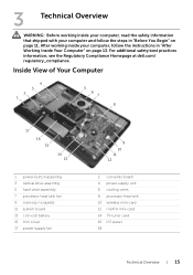
... Regulatory Compliance Homepage at dell.com/ regulatory_compliance. Inside View of Your Computer 4 3 2 1 5 6 7 8 17 16 15 14 13 1 power-button assembly 3 optical-drive assembly 5 hard-drive assembly 7 processor heat-sink fan 9 memory module(s) 11 system board 13 coin-cell battery 15 trim cover 17 power-supply fan 9 10 11 12 2 converter board 4 power-supply unit 6 cooling vents...
... Regulatory Compliance Homepage at dell.com/ regulatory_compliance. Inside View of Your Computer 4 3 2 1 5 6 7 8 17 16 15 14 13 1 power-button assembly 3 optical-drive assembly 5 hard-drive assembly 7 processor heat-sink fan 9 memory module(s) 11 system board 13 coin-cell battery 15 trim cover 17 power-supply fan 9 10 11 12 2 converter board 4 power-supply unit 6 cooling vents...

Owner's Manual (PDF)
Page 35
...You Begin" on page 11. Removing the Power-Supply Unit | 35 See "Removing the Trim Cover" on page 47. 3 Remove the system-board shield. For additional safety best practices information, see the Regulatory Compliance Homepage at dell.com/ regulatory_compliance. See "Removing the Back ...Cover" on page 31. 4 Remove the trim cover. 12 Removing the Power-Supply Unit WARNING: Before working inside your computer, read the safety information...
...You Begin" on page 11. Removing the Power-Supply Unit | 35 See "Removing the Trim Cover" on page 47. 3 Remove the system-board shield. For additional safety best practices information, see the Regulatory Compliance Homepage at dell.com/ regulatory_compliance. See "Removing the Back ...Cover" on page 31. 4 Remove the trim cover. 12 Removing the Power-Supply Unit WARNING: Before working inside your computer, read the safety information...
Owner's Manual (PDF)
Page 36
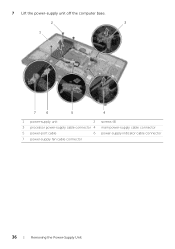
7 Lift the power-supply unit off the computer base. 2 3 1 7 6 5 4 1 power-supply unit 2 screws (4) 3 processor power-supply cable connector 4 main power-supply cable connector 5 power-port cable 6 power-supply indicator cable connector 7 power-supply fan cable connector 36 | Removing the Power-Supply Unit
7 Lift the power-supply unit off the computer base. 2 3 1 7 6 5 4 1 power-supply unit 2 screws (4) 3 processor power-supply cable connector 4 main power-supply cable connector 5 power-port cable 6 power-supply indicator cable connector 7 power-supply fan cable connector 36 | Removing the Power-Supply Unit

Owner's Manual (PDF)
Page 37
... the power-supply indicator cable to the power-supply unit. 4 Connect the power-port cable to the power-supply unit. 5 Route the processor and main power-supply cables through their routing guides. 6 Connect the processor and main power-supply cables to the system board. Replacing the Power-Supply Unit | 37 For additional safety best practices information, see the Regulatory Compliance Homepage at dell.com...
... the power-supply indicator cable to the power-supply unit. 4 Connect the power-port cable to the power-supply unit. 5 Route the processor and main power-supply cables through their routing guides. 6 Connect the processor and main power-supply cables to the system board. Replacing the Power-Supply Unit | 37 For additional safety best practices information, see the Regulatory Compliance Homepage at dell.com...

Owner's Manual (PDF)
Page 38
38 | Replacing the Power-Supply Unit
38 | Replacing the Power-Supply Unit
Owner's Manual (PDF)
Page 59
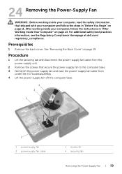
...working inside your computer, read the safety information that secure the power-supply fan to the computer base. 3 Gently lift the power-supply fan and ease the power-supply fan cable from the power-supply unit. 2 Remove the screws that shipped with your computer, ... 1 Lift the securing tab and disconnect the power-supply fan cable from under the I/O-board assembly. 4 Lift the power-supply fan off the computer base. 4 3 2 1 1 power-supply fan 3 power-supply fan cable 2 screws (2) 4 securing tab Removing the Power-Supply Fan | 59 For additional safety best practices information...
...working inside your computer, read the safety information that secure the power-supply fan to the computer base. 3 Gently lift the power-supply fan and ease the power-supply fan cable from the power-supply unit. 2 Remove the screws that shipped with your computer, ... 1 Lift the securing tab and disconnect the power-supply fan cable from under the I/O-board assembly. 4 Lift the power-supply fan off the computer base. 4 3 2 1 1 power-supply fan 3 power-supply fan cable 2 screws (2) 4 securing tab Removing the Power-Supply Fan | 59 For additional safety best practices information...

Owner's Manual (PDF)
Page 60
60 | Removing the Power-Supply Fan
60 | Removing the Power-Supply Fan
Owner's Manual (PDF)
Page 61
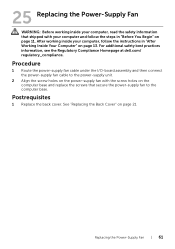
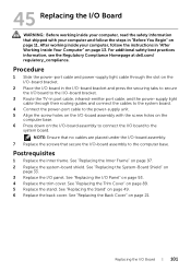
...information, see the Regulatory Compliance Homepage at dell.com/ regulatory_compliance. Procedure 1 Route the power-supply fan cable under the I/O-board assembly and then connect the power-supply fan cable to the power-supply unit. 2 Align the screw holes on the power-supply fan with your computer and follow the ...screws that shipped with the screw holes on page 21. 25 Replacing the Power-Supply Fan WARNING: Before working inside your computer, read the safety information that secure the power-supply fan to the computer base. After working inside your computer, follow the steps...
...information, see the Regulatory Compliance Homepage at dell.com/ regulatory_compliance. Procedure 1 Route the power-supply fan cable under the I/O-board assembly and then connect the power-supply fan cable to the power-supply unit. 2 Align the screw holes on the power-supply fan with your computer and follow the ...screws that shipped with the screw holes on page 21. 25 Replacing the Power-Supply Fan WARNING: Before working inside your computer, read the safety information that secure the power-supply fan to the computer base. After working inside your computer, follow the steps...

Owner's Manual (PDF)
Page 62
62 | Replacing the Power-Supply Fan
62 | Replacing the Power-Supply Fan
Owner's Manual (PDF)
Page 99
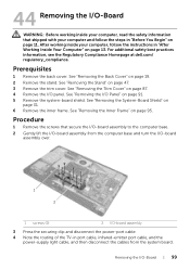
... 1 2 1 screws (9) 2 I/O-board assembly 3 Press the securing clip and disconnect the power-port cable. 4 Note the routing of the TV-in port cable, infrared-emitter port cable, and the power-supply light cable, and then disconnect the cables from the system board. See "Removing the Back ... Your Computer" on page 47. 3 Remove the trim cover. For additional safety best practices information, see the Regulatory Compliance Homepage at dell.com/ regulatory_compliance. See "Removing the Stand" on page 13. After working inside your computer and follow the instructions in "Before You...
... 1 2 1 screws (9) 2 I/O-board assembly 3 Press the securing clip and disconnect the power-port cable. 4 Note the routing of the TV-in port cable, infrared-emitter port cable, and the power-supply light cable, and then disconnect the cables from the system board. See "Removing the Back ... Your Computer" on page 47. 3 Remove the trim cover. For additional safety best practices information, see the Regulatory Compliance Homepage at dell.com/ regulatory_compliance. See "Removing the Stand" on page 13. After working inside your computer and follow the instructions in "Before You...
Owner's Manual (PDF)
Page 100
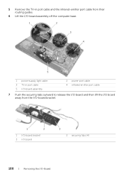
5 Remove the TV-in port cable and the infrared-emitter port cable from their routing guides. 6 Lift the I/O-board assembly off the computer base. 1 2 3 4 5 1 power-supply light cable 3 TV-in port cable 5 I/O-board assembly 2 power-port cable 4 infrared-emitter port cable 7 Push the securing tabs outward to release the I/O board and then lift the I/O board away from the I/O-board bracket. 1 2 1 I/O-board bracket 3 I/O board 3 2 securing tabs (4) 100 | Removing the I/O-Board
5 Remove the TV-in port cable and the infrared-emitter port cable from their routing guides. 6 Lift the I/O-board assembly off the computer base. 1 2 3 4 5 1 power-supply light cable 3 TV-in port cable 5 I/O-board assembly 2 power-port cable 4 infrared-emitter port cable 7 Push the securing tabs outward to release the I/O board and then lift the I/O board away from the I/O-board bracket. 1 2 1 I/O-board bracket 3 I/O board 3 2 securing tabs (4) 100 | Removing the I/O-Board
Owner's Manual (PDF)
Page 101
... the I/O-board bracket. 3 Route the TV-in port cable, infrared-emitter port cable, and the power-supply light cable through their routing guides and connect the cables to the system board. 4 Connect the power-port cable to the power-supply unit. 5 Align the screw holes on the I/O-board assembly with your computer and follow the... computer base. 6 Press down on the I/O-board assembly to connect the I /O Board | 101 For additional safety best practices information, see the Regulatory Compliance Homepage at dell.com/ regulatory_compliance. Replacing the I /O board to the computer base.
... the I/O-board bracket. 3 Route the TV-in port cable, infrared-emitter port cable, and the power-supply light cable through their routing guides and connect the cables to the system board. 4 Connect the power-port cable to the power-supply unit. 5 Align the screw holes on the I/O-board assembly with your computer and follow the... computer base. 6 Press down on the I/O-board assembly to connect the I /O Board | 101 For additional safety best practices information, see the Regulatory Compliance Homepage at dell.com/ regulatory_compliance. Replacing the I /O board to the computer base.

Owner's Manual (PDF)
Page 112
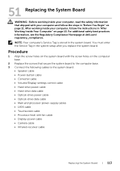
...-settings control cable • Hard-drive data cable • Hard-drive power cable • Optical-drive data cable • Optical-drive power cable • Main and processor power-supply cables • LVDS cable • Touchscreen cable • Processor heat-sink fan cable • Display-power cable • Camera cable • Infrared-receiver cable NOTE: For...
...-settings control cable • Hard-drive data cable • Hard-drive power cable • Optical-drive data cable • Optical-drive power cable • Main and processor power-supply cables • LVDS cable • Touchscreen cable • Processor heat-sink fan cable • Display-power cable • Camera cable • Infrared-receiver cable NOTE: For...
Owner's Manual (PDF)
Page 113
...the system board with the screw holes on page 11. For additional safety best practices information, see the Regulatory Compliance Homepage at dell.com/ regulatory_compliance. You must enter the Service Tag in "Before You Begin" on the computer base. 2 Replace the screws ...control cable • Hard-drive power cable • Hard-drive data cable • Optical-drive power cable • Optical-drive data cable • Main and processor power-supply cables • LVDS cable • Touchscreen cable • Processor heat-sink fan cable • Display-power cable • Camera cable ...
...the system board with the screw holes on page 11. For additional safety best practices information, see the Regulatory Compliance Homepage at dell.com/ regulatory_compliance. You must enter the Service Tag in "Before You Begin" on the computer base. 2 Replace the screws ...control cable • Hard-drive power cable • Hard-drive data cable • Optical-drive power cable • Optical-drive data cable • Main and processor power-supply cables • LVDS cable • Touchscreen cable • Processor heat-sink fan cable • Display-power cable • Camera cable ...
Owner's Manual (PDF)
Page 127
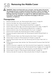
...Prerequisites 1 Remove the back cover. See "Removing the Trim Cover" on page 79. 12 Remove the processor heat-sink fan. See "Removing the Power-Supply Unit" on page 123. See "Removing the Side I /O-board. After working inside your computer and follow the instructions in "After Working Inside ...steps in "Before You Begin" on page 11. See "Removing the System-Board Shield" on page 75. 13 Remove the power-supply fan. See "Removing the Power-Supply Fan" on page 59. 14 Remove the power-supply unit. For additional safety best practices information, see the Regulatory Compliance Homepage at...
...Prerequisites 1 Remove the back cover. See "Removing the Trim Cover" on page 79. 12 Remove the processor heat-sink fan. See "Removing the Power-Supply Unit" on page 123. See "Removing the Side I /O-board. After working inside your computer and follow the instructions in "After Working Inside ...steps in "Before You Begin" on page 11. See "Removing the System-Board Shield" on page 75. 13 Remove the power-supply fan. See "Removing the Power-Supply Fan" on page 59. 14 Remove the power-supply unit. For additional safety best practices information, see the Regulatory Compliance Homepage at...
Owner's Manual (PDF)
Page 132
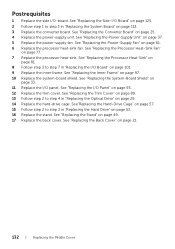
...panel. See "Replacing the Back Cover" on page 93. 12 Replace the trim cover. See "Replacing the Inner Frame" on page 37. 5 Replace the power-supply fan. See "Replacing the Trim Cover" on page 89. 13 Follow step 2 to step 7 in "Replacing the Optical Drive" on page 29. 14 Replace... the Stand" on page 33. 11 Replace the I /O Panel" on page 21. 132 | Replacing the Middle Cover See "Replacing the Power-Supply Fan" on page 25. 4 Replace the power-supply unit. See "Replacing the Side-I /O-board. See "Replacing the Converter Board" on page 61. 6 Replace the processor heat-sink fan. See...
...panel. See "Replacing the Back Cover" on page 93. 12 Replace the trim cover. See "Replacing the Inner Frame" on page 37. 5 Replace the power-supply fan. See "Replacing the Trim Cover" on page 89. 13 Follow step 2 to step 7 in "Replacing the Optical Drive" on page 29. 14 Replace... the Stand" on page 33. 11 Replace the I /O Panel" on page 21. 132 | Replacing the Middle Cover See "Replacing the Power-Supply Fan" on page 25. 4 Replace the power-supply unit. See "Replacing the Side-I /O-board. See "Replacing the Converter Board" on page 61. 6 Replace the processor heat-sink fan. See...


