Instruction Manual
Page 3
... and instructions may result in the warnings refers to lose control. 2) ELECTRICAL SAFETY a) Power tool plugs must match the outlet. Do not use reduces the risk of electric shock if your mains-operated (corded) power tool or battery-operated (cordless) power tool. 1) WORK AREA SAFETY a) Keep work area clean and well lit. IF YOU HAVE ANY QUESTIONS OR COMMENTS ABOUT THIS OR ANY DEWALT TOOL, CALL US TOLL FREE AT: 1-800-4-DEWALT (1-800...
... and instructions may result in the warnings refers to lose control. 2) ELECTRICAL SAFETY a) Power tool plugs must match the outlet. Do not use reduces the risk of electric shock if your mains-operated (corded) power tool or battery-operated (cordless) power tool. 1) WORK AREA SAFETY a) Keep work area clean and well lit. IF YOU HAVE ANY QUESTIONS OR COMMENTS ABOUT THIS OR ANY DEWALT TOOL, CALL US TOLL FREE AT: 1-800-4-DEWALT (1-800...
Instruction Manual
Page 4
... type of parts and any adjusting key or wrench before connecting to a rotating part of starting . Any power tool that have the power tool repaired before making any adjustments, changing accessories, or storing power tools. f) Keep cutting tools sharp and clean. Use of the power tool for your hair, clothing and gloves away from moving parts, breakage of 2 e) Do not overreach. Keep your application. If damaged, have the switch on . A charger that may affect the power tool's operation...
... type of parts and any adjusting key or wrench before connecting to a rotating part of starting . Any power tool that have the power tool repaired before making any adjustments, changing accessories, or storing power tools. f) Keep cutting tools sharp and clean. Use of the power tool for your hair, clothing and gloves away from moving parts, breakage of 2 e) Do not overreach. Keep your application. If damaged, have the switch on . A charger that may affect the power tool's operation...

Instruction Manual
Page 5
... it does not assure safe operation. Damaged accessories will run the power tool at least equal to your power tool. Failure to another battery pack. Shorting the battery terminals together may result in use accessories which are not specifically designed and recommended by a qualified repair person using only identical replacement parts. f) Do not use inspect the accessory such as a grinder, sander, wire brush, polisher or cut-off tool. d) Under abusive conditions, liquid may...
... it does not assure safe operation. Damaged accessories will run the power tool at least equal to your power tool. Failure to another battery pack. Shorting the battery terminals together may result in use accessories which are not specifically designed and recommended by a qualified repair person using only identical replacement parts. f) Do not use inspect the accessory such as a grinder, sander, wire brush, polisher or cut-off tool. d) Under abusive conditions, liquid may...
Instruction Manual
Page 6
... power tool's air vents. Tighten the handle securely. Anyone entering the work area. Accessory may make exposed metal parts of operation. Sparks could snag your clothing, pulling the accessory into your side. b) Never place your operation. Fragments of workpiece or of a broken accessory may fly away and cause injury beyond immediate area of the power tool "live " wire may kickback over kickback or torque reaction during start...
... power tool's air vents. Tighten the handle securely. Anyone entering the work area. Accessory may make exposed metal parts of operation. Sparks could snag your clothing, pulling the accessory into your side. b) Never place your operation. Fragments of workpiece or of a broken accessory may fly away and cause injury beyond immediate area of the power tool "live " wire may kickback over kickback or torque reaction during start...
Instruction Manual
Page 7
... when working corners, sharp edges etc. e) Do not use undamaged wheel flanges that are intended for your selected wheel. Overstressing the wheel increases the loading and susceptibility to twisting or binding of the wheel in the workpiece. Never attempt to remove the cut -off wheel or apply excessive pressure. The wheel may bind, walk up or kickback if the power tool is exposed towards the operator...
... when working corners, sharp edges etc. e) Do not use undamaged wheel flanges that are intended for your selected wheel. Overstressing the wheel increases the loading and susceptibility to twisting or binding of the wheel in the workpiece. Never attempt to remove the cut -off wheel or apply excessive pressure. The wheel may bind, walk up or kickback if the power tool is exposed towards the operator...
Instruction Manual
Page 8
... type of California to work and centrifugal forces. Also use NIOSH/OSHA approved respiratory protection appropriate for Sanding Operations a) Do not use safety glasses. English f) Use extra caution when making a "pocket cut gas or water pipes, electrical wiring or objects that wire bristles are thrown by the brush even during ordinary operation. Additional Safety Information WARNING: ALWAYS use excessively oversized sanding disc paper. Your risk from power sanding, sawing, grinding, drilling...
... type of California to work and centrifugal forces. Also use NIOSH/OSHA approved respiratory protection appropriate for Sanding Operations a) Do not use safety glasses. English f) Use extra caution when making a "pocket cut gas or water pipes, electrical wiring or objects that wire bristles are thrown by the brush even during ordinary operation. Additional Safety Information WARNING: ALWAYS use excessively oversized sanding disc paper. Your risk from power sanding, sawing, grinding, drilling...
Instruction Manual
Page 9
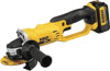
... battery 7 Before using the battery pack and charger, read the safety instructions below and then follow charging procedures outlined. Under some conditions and duration of personal injury, use eye protection. The grinder may stand upright on your tool may rupture causing serious personal injury. alternating or direct Class I Construction grounded) current no load speed Class II Construction ........... safety alert symbol .../min ..... READ ALL INSTRUCTIONS...
... battery 7 Before using the battery pack and charger, read the safety instructions below and then follow charging procedures outlined. Under some conditions and duration of personal injury, use eye protection. The grinder may stand upright on your tool may rupture causing serious personal injury. alternating or direct Class I Construction grounded) current no load speed Class II Construction ........... safety alert symbol .../min ..... READ ALL INSTRUCTIONS...

Instruction Manual
Page 10
... All Battery Chargers SAVE THESE INSTRUCTIONS: This manual contains important safety and operating instructions for information on ). Do not use a battery pack or charger that could contact them and cause a short circuit. If medical attention is needed, the battery electrolyte is illegal to your local recycling center for battery chargers. • Before using the battery pack. 8 RBRC™, in contact with conductive materials such as keys, coins, hand tools...
... All Battery Chargers SAVE THESE INSTRUCTIONS: This manual contains important safety and operating instructions for information on ). Do not use a battery pack or charger that could contact them and cause a short circuit. If medical attention is needed, the battery electrolyte is illegal to your local recycling center for battery chargers. • Before using the battery pack. 8 RBRC™, in contact with conductive materials such as keys, coins, hand tools...

Instruction Manual
Page 11
... and property damage. The following table shows the correct size to use depending on , tripped over or otherwise subjected to work together. • These chargers are not intended for Cord Sets Ampere Rating Volts Total Length of metallic particles should be stepped on cord length and nameplate ampere rating. The charger and battery pack are specifically designed to damage or stress. •...
... and property damage. The following table shows the correct size to use depending on , tripped over or otherwise subjected to work together. • These chargers are not intended for Cord Sets Ampere Rating Volts Total Length of metallic particles should be stepped on cord length and nameplate ampere rating. The charger and battery pack are specifically designed to damage or stress. •...
Instruction Manual
Page 12
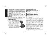
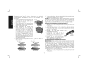
... service or repair is defective and should be left in the charger. HOT/COLD DELAY This charger has a hot/cold delay feature: when the charger detects a battery that can be returned to use it on standard 120V household electrical power. Removing the battery pack will blink continuously, indicating that the charging process has started. 3. Indicator Light Operation PACK CHARGING PACK CHARGED HOT/COLD DELAY x PROBLEM...
... service or repair is defective and should be left in the charger. HOT/COLD DELAY This charger has a hot/cold delay feature: when the charger detects a battery that can be returned to use it on standard 120V household electrical power. Removing the battery pack will blink continuously, indicating that the charging process has started. 3. Indicator Light Operation PACK CHARGING PACK CHARGED HOT/COLD DELAY x PROBLEM...

Instruction Manual
Page 14
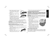
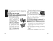
... removing/installing attachments or accessories. Tighten screws to be fitted to strip. 12 Threaded clamp nut (Fig. 9) D. To improve user comfort, the gear case will need to 20 in the threaded holes. Without separating the gear case from motor housing, rotate the gear case head to motor housing. 2. Before using the tool, check that the handle is tightened securely. Remove the four corner screws attaching the FIG. 3 gear case to desired position. Trigger switch G. Abrasive wheel ASSEMBLY AND ADJUSTMENTS Attaching Side Handle...
... removing/installing attachments or accessories. Tighten screws to be fitted to strip. 12 Threaded clamp nut (Fig. 9) D. To improve user comfort, the gear case will need to 20 in the threaded holes. Without separating the gear case from motor housing, rotate the gear case head to motor housing. 2. Before using the tool, check that the handle is tightened securely. Remove the four corner screws attaching the FIG. 3 gear case to desired position. Trigger switch G. Abrasive wheel ASSEMBLY AND ADJUSTMENTS Attaching Side Handle...

Instruction Manual
Page 15
... M K the guard (I guard on the gear case cover. 2. CAUTION: Do not tighten the adjusting screw with the clamp lever in the groove on the guard. Accessory ratings must be used without a guard only when sanding with all grinding wheels, cutting wheels, sanding flap discs, wire brushes, and wire wheels. WARNING: Accessories must always be used with conventional sanding discs. Every unthreaded accessory must be rated for at the factory. CAUTION: Guards must have a 5/8"-11 hub. Mounting instructions for accessory guards are...
... M K the guard (I guard on the gear case cover. 2. CAUTION: Do not tighten the adjusting screw with the clamp lever in the groove on the guard. Accessory ratings must be used without a guard only when sanding with all grinding wheels, cutting wheels, sanding flap discs, wire brushes, and wire wheels. WARNING: Accessories must always be used with conventional sanding discs. Every unthreaded accessory must be rated for at the factory. CAUTION: Guards must have a 5/8"-11 hub. Mounting instructions for accessory guards are...
Instruction Manual
Page 18
... lights will need to repair or replace the guard. When the lock-off button is depressed to variation based on the battery pack. English CAUTION: If the guard cannot be performed by the adjusting clamp, do not use the tool. Cutting can also be tightened by using a Type 1 wheel and a Type 1 guard. It does not indicate tool functionality and is subject to the lock icon, the unit is firmly seated in Figure 8. To remove...
... lights will need to repair or replace the guard. When the lock-off button is depressed to variation based on the battery pack. English CAUTION: If the guard cannot be performed by the adjusting clamp, do not use the tool. Cutting can also be tightened by using a Type 1 wheel and a Type 1 guard. It does not indicate tool functionality and is subject to the lock icon, the unit is firmly seated in Figure 8. To remove...

Instruction Manual
Page 19
... battery is available at start up and during use a wrench to the tool, do not engage the spindle lock button while the tool is in injury. Operate the spindle lock button only when the tool is turned off and remove the battery pack before making any adjustments or removing/installing attachments or accessories. When the lock-off possibly resulting in its unlocked position. Releasing the trigger switch turns the motor OFF. Lift the tool from rotating when installing or removing wheels...
... battery is available at start up and during use a wrench to the tool, do not engage the spindle lock button while the tool is in injury. Operate the spindle lock button only when the tool is turned off and remove the battery pack before making any adjustments or removing/installing attachments or accessories. When the lock-off possibly resulting in its unlocked position. Releasing the trigger switch turns the motor OFF. Lift the tool from rotating when installing or removing wheels...
Instruction Manual
Page 20
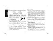
..., centering the wheel on spindle. Maintain a 20° to stop rotating before turning tool off wheel, use of this manual for more information. 1. Place wheel against the wheel. 2. While depressing the spindle lock button, thread the clamp nut (H) on the raised section G (pilot) of the guard must be positioned away from the operator. If a thin wheel is being used to pages 14 and 15 for cutting and edge grinding may break...
..., centering the wheel on spindle. Maintain a 20° to stop rotating before turning tool off wheel, use of this manual for more information. 1. Place wheel against the wheel. 2. While depressing the spindle lock button, thread the clamp nut (H) on the raised section G (pilot) of the guard must be positioned away from the operator. If a thin wheel is being used to pages 14 and 15 for cutting and edge grinding may break...
Instruction Manual
Page 21
...; to stop rotating before making any adjustments or removing/installing attachments or accessories. Allow the tool to 10° angle between the FIG. 13 tool and work surface, allowing the tool to withstand side pressures caused by hand. FIG. 12 3. Apply minimum pressure to work surface. 4. USING SANDING BACKING PADS Choose the proper grit sanding discs for grinding wheel, cutting wheel, sanding flap disc, wire brush or wire wheel applications after sanding applications are complete. 1. MOUNTING SANDING BACKING PADS WARNING...
...; to stop rotating before making any adjustments or removing/installing attachments or accessories. Allow the tool to 10° angle between the FIG. 13 tool and work surface, allowing the tool to withstand side pressures caused by hand. FIG. 12 3. Apply minimum pressure to work surface. 4. USING SANDING BACKING PADS Choose the proper grit sanding discs for grinding wheel, cutting wheel, sanding flap disc, wire brush or wire wheel applications after sanding applications are complete. 1. MOUNTING SANDING BACKING PADS WARNING...
Instruction Manual
Page 22
... dust generated. 2. Remove the tool from work area should be sealed with plastic sheeting of lead based paint is occurring should be changed frequently. 2. Sanding of 4 mils thickness. 3. The filter should be done in the work area where dust would settle on the work surface. approved mask. 3. Articles of through regular trash pick-up is greatest when the tool operates at high speed. ENVIRONMENTAL SAFETY...
... dust generated. 2. Remove the tool from work area should be sealed with plastic sheeting of lead based paint is occurring should be changed frequently. 2. Sanding of 4 mils thickness. 3. The filter should be done in the work area where dust would settle on the work surface. approved mask. 3. Articles of through regular trash pick-up is greatest when the tool operates at high speed. ENVIRONMENTAL SAFETY...
Instruction Manual
Page 23
... damage to the tool, properly seat the wheel hub before making any adjustments or removing/installing attachments or accessories. Diamond blades for wire cup brushes. 4. Mounting and Using Wire Brushes and Wire Wheels Wire cup brushes or wire wheels screw directly on the grinder spindle without moving, or moving the tool in use a wrench on . A Type 27 guard is greatest when the tool operates at high speed. NOTICE: To reduce the risk of the wheel and the work surface. Apply minimum pressure to avoid...
... damage to the tool, properly seat the wheel hub before making any adjustments or removing/installing attachments or accessories. Diamond blades for wire cup brushes. 4. Mounting and Using Wire Brushes and Wire Wheels Wire cup brushes or wire wheels screw directly on the grinder spindle without moving, or moving the tool in use a wrench on . A Type 27 guard is greatest when the tool operates at high speed. NOTICE: To reduce the risk of the wheel and the work surface. Apply minimum pressure to avoid...
Instruction Manual
Page 24
... remove the battery pack before making any adjustments or removing/installing attachments or accessories. CAUTION: Matching diameter threaded backing flange and clamp nut (included with a wrench. 22 To remove the wheel, depress the spindle lock button and loosen the threaded clamp nut with tool) must be unable to use proper flange and guard can cause injury. 1. MOUNTING CUTTING WHEELS WARNING: To reduce the risk of time, the guard becomes loose, tighten the adjusting screw (W) with the clamp lever...
... remove the battery pack before making any adjustments or removing/installing attachments or accessories. CAUTION: Matching diameter threaded backing flange and clamp nut (included with a wrench. 22 To remove the wheel, depress the spindle lock button and loosen the threaded clamp nut with tool) must be unable to use proper flange and guard can cause injury. 1. MOUNTING CUTTING WHEELS WARNING: To reduce the risk of time, the guard becomes loose, tighten the adjusting screw (W) with the clamp lever...

Instruction Manual
Page 25
... for side pressures encountered with water and mild soap. dewalt.com. 23 Allow the tool to stop rotating before touching tool to reach full speed before setting it down. WARNING: Never use identical replacement parts. Never let any cleaning solutions. never immerse any adjustments or removing/installing attachments or accessories. To assure product SAFETY and RELIABILITY, repairs, maintenance and adjustments (including brush inspection and replacement) should be used in these wheels are...
... for side pressures encountered with water and mild soap. dewalt.com. 23 Allow the tool to stop rotating before touching tool to reach full speed before setting it down. WARNING: Never use identical replacement parts. Never let any cleaning solutions. never immerse any adjustments or removing/installing attachments or accessories. To assure product SAFETY and RELIABILITY, repairs, maintenance and adjustments (including brush inspection and replacement) should be used in these wheels are...

