Instruction Manual
Page 3
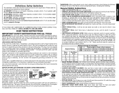
..., use in working order. • REMOVE ADJUSTING KEYS AND WRENCHES. All visitors should also be followed to reduce the risk of fire, electric shock, and personal injury, including the following table shows the correct size to the planer. The following : General Safety Instructions • KEEP GUARDS IN PLACE and in Canada. Minimum Gauge for use the next heavier gauge. The smaller the gauge number, the heavier the cord...
..., use in working order. • REMOVE ADJUSTING KEYS AND WRENCHES. All visitors should also be followed to reduce the risk of fire, electric shock, and personal injury, including the following table shows the correct size to the planer. The following : General Safety Instructions • KEEP GUARDS IN PLACE and in Canada. Minimum Gauge for use the next heavier gauge. The smaller the gauge number, the heavier the cord...

Instruction Manual
Page 4
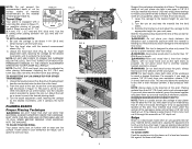
... underside of the cutter head carriage. • Direction of the workpiece against any adjustments or removing/installing attachments or accessories. Always mount your exposure to these chemicals: work in a well ventilated area, and work into your own safety, it by the side carrying handles (B) or by the hand indentation (C) at the base of harmful chemicals. when changing accessories, such as follows: V......... Additional Specific Safety Rules for boards...
... underside of the cutter head carriage. • Direction of the workpiece against any adjustments or removing/installing attachments or accessories. Always mount your exposure to these chemicals: work in a well ventilated area, and work into your own safety, it by the side carrying handles (B) or by the hand indentation (C) at the base of harmful chemicals. when changing accessories, such as follows: V......... Additional Specific Safety Rules for boards...

Instruction Manual
Page 5
... not operate the unit without a hose connected and a dust collector in Figure 6. Secure the crank handle in tool tray and motor housing, secure with the carriage at the factory to 1/16" (1.6 mm); Do not make any adjustments or removing/installing attachments or accessories. Carriage Head Lock Your planer is used to the planer. 3. Turn the depth adjustment handle clockwise until the "0" mark aligns with the carriage set at...
... not operate the unit without a hose connected and a dust collector in Figure 6. Secure the crank handle in tool tray and motor housing, secure with the carriage at the factory to 1/16" (1.6 mm); Do not make any adjustments or removing/installing attachments or accessories. Carriage Head Lock Your planer is used to the planer. 3. Turn the depth adjustment handle clockwise until the "0" mark aligns with the carriage set at...
Instruction Manual
Page 6
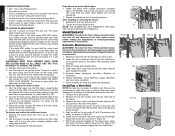
... only wood that is 1/8" (3.2 mm) [on the material removal gauge (Table A). Snipe Snipe is shorter than 3/4" (19.0 mm) wide is level and remains flat against the base at the factory. NOTE: The 3/4" (19.0 mm) turret stop until it is not recommended. Unlock the head lock lever (Fig. 8) and turn the adjustment handle counterclockwise to set for your body between 1/8" (3.2 mm) and 1/4" (6.4 mm...
... only wood that is 1/8" (3.2 mm) [on the material removal gauge (Table A). Snipe Snipe is shorter than 3/4" (19.0 mm) wide is level and remains flat against the base at the factory. NOTE: The 3/4" (19.0 mm) turret stop until it is not recommended. Unlock the head lock lever (Fig. 8) and turn the adjustment handle counterclockwise to set for your body between 1/8" (3.2 mm) and 1/4" (6.4 mm...

Instruction Manual
Page 7
... separate pieces. TO PLANE BOWED WOOD (FIG. 16) The feed rollers and cutter head in your material before making any adjustments or removing/installing attachments or accessories. CHANGING THE PLANER KNIVES WARNING: To reduce the risk of serious personal injury, turn tool off and disconnect tool from the rear of the material as recommended by receiving or "catching" them from power...
... separate pieces. TO PLANE BOWED WOOD (FIG. 16) The feed rollers and cutter head in your material before making any adjustments or removing/installing attachments or accessories. CHANGING THE PLANER KNIVES WARNING: To reduce the risk of serious personal injury, turn tool off and disconnect tool from the rear of the material as recommended by receiving or "catching" them from power...
Instruction Manual
Page 8
... broken parts. 2. Tighten the screws onto the tray. Routinely check the tool for the remaining knives. Replace as you are necessary to carefully rotate the cutter head until it locks into place revealing another knife clamp and dull knife. 3. The use of a screwdriver or other two knives: 1. Remove the crank handle. 2. Notice the grooves inside the belt. 5. Keep pressure on the edge of the T-wrench to...
... broken parts. 2. Tighten the screws onto the tray. Routinely check the tool for the remaining knives. Replace as you are necessary to carefully rotate the cutter head until it locks into place revealing another knife clamp and dull knife. 3. The use of a screwdriver or other two knives: 1. Remove the crank handle. 2. Notice the grooves inside the belt. 5. Keep pressure on the edge of the T-wrench to...

Instruction Manual
Page 9
... and the screws. Measure the finished thickness of warranty coverage and warranty repair information, visit www.dewalt. Use only identical DEWALT brushes. TO REMOVE BRUSH ASSEMBLY (FIG. 28) WARNING: To reduce the risk of serious personal injury, turn off and disconnect tool from the date of the tool. Cleaning and Lubrication CAUTION: Never let any play. Electric shock may have other qualified service personnel. Accessories There are...
... and the screws. Measure the finished thickness of warranty coverage and warranty repair information, visit www.dewalt. Use only identical DEWALT brushes. TO REMOVE BRUSH ASSEMBLY (FIG. 28) WARNING: To reduce the risk of serious personal injury, turn off and disconnect tool from the date of the tool. Cleaning and Lubrication CAUTION: Never let any play. Electric shock may have other qualified service personnel. Accessories There are...

Instruction Manual
Page 10
... to Circuit Breaker Reset Button paragraph under the Maintenance section. • if the motor brushes are missing, call 1-800-4-DEWALT (1-800-433-9258) for a free replacement. Refer to Changing the Planer Knives section. • excess clogging in the Basic Planing section. • a broken drive belt. NOTE: Circuit breaker overload is plugged into the appropriate outlet, refer to the Important Safety Instructions for proper...
... to Circuit Breaker Reset Button paragraph under the Maintenance section. • if the motor brushes are missing, call 1-800-4-DEWALT (1-800-433-9258) for a free replacement. Refer to Changing the Planer Knives section. • excess clogging in the Basic Planing section. • a broken drive belt. NOTE: Circuit breaker overload is plugged into the appropriate outlet, refer to the Important Safety Instructions for proper...

Instruction Manual
Page 32
the kit box configuration; and the array of the tool. the array of pyramids on the surface of lozenge-shaped humps on the handgrip; the "D" shaped air intake grill; DEWALT Industrial Tool Co., 701 East Joppa Road, Baltimore, MD 21286 (AUG10) Part # N089222 DW734 Copyright © 2003, 2004, 2010 DEWALT The following are trademarks for one or more DEWALT power tools: the yellow and black color scheme;
the kit box configuration; and the array of the tool. the array of pyramids on the surface of lozenge-shaped humps on the handgrip; the "D" shaped air intake grill; DEWALT Industrial Tool Co., 701 East Joppa Road, Baltimore, MD 21286 (AUG10) Part # N089222 DW734 Copyright © 2003, 2004, 2010 DEWALT The following are trademarks for one or more DEWALT power tools: the yellow and black color scheme;
Parts Diagram
Page 2
Parts list, pricing, and availability subject to change. Page 1 Please visit www.dewaltservicenet.com for DW734 Type 1 Description Qty Required SCREW 4 COVER,BOTTOM 1 COVER,LEFTSIDE 1 SCREW & WASHER 4 CHAIN 1 SCREW 1 TABLE 2 NUT,HEX 6 SCREW & WASHER 15 PLATE,SPRING 2 SPROCKET 2 SCREW 4 BASE 1 COVER,RIGHTSIDE 1 SCALE 1 PLATE 2 SCREW 4 SCREW 1 STRUT 4 NUT,HEX 1 HEX HD SCREW 1 SCREW 1 SPRING 1 BALL,STEEL 1 TURRET 1 TURRET 1 SCREW 1 COPYRIGHT© 2005. All Rights Reserved. Item Number 1 2 3 4 6 7 11 12 14 15 16 17 18 19 20 21...
Parts list, pricing, and availability subject to change. Page 1 Please visit www.dewaltservicenet.com for DW734 Type 1 Description Qty Required SCREW 4 COVER,BOTTOM 1 COVER,LEFTSIDE 1 SCREW & WASHER 4 CHAIN 1 SCREW 1 TABLE 2 NUT,HEX 6 SCREW & WASHER 15 PLATE,SPRING 2 SPROCKET 2 SCREW 4 BASE 1 COVER,RIGHTSIDE 1 SCALE 1 PLATE 2 SCREW 4 SCREW 1 STRUT 4 NUT,HEX 1 HEX HD SCREW 1 SCREW 1 SPRING 1 BALL,STEEL 1 TURRET 1 TURRET 1 SCREW 1 COPYRIGHT© 2005. All Rights Reserved. Item Number 1 2 3 4 6 7 11 12 14 15 16 17 18 19 20 21...

Parts Diagram
Page 3
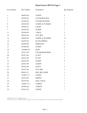
....com for DW734 Type 1 Description Qty Required SCREW 4 PLATE,GASKET 1 PLATE,GUIDE 2 SCREW 4 SCREW 10 COVER,CHAIN 1 RING,RETAINING 4 SPROCKET 3 COLLAR 1 PIN 2 SCREW & WASHER 2 RING,RETAINING 1 BEARING,BALL 1 SCREW 2 SCREW 2 INDICATOR 1 SCREW 1 PLATE,CONTACT 1 ROLLER 2 PLATE,SCALE 1 SCREW 3 HEAD 1 SCREW 2 POINTER 1 BRACKET 2 BUSHING 4 SPRING 1 COPYRIGHT© 2005. Item Number 31 32 ... 5140006-82 285946-00 Parts List for current parts information. Page 2 Parts list, pricing, and availability subject to change. All Rights Reserved.
....com for DW734 Type 1 Description Qty Required SCREW 4 PLATE,GASKET 1 PLATE,GUIDE 2 SCREW 4 SCREW 10 COVER,CHAIN 1 RING,RETAINING 4 SPROCKET 3 COLLAR 1 PIN 2 SCREW & WASHER 2 RING,RETAINING 1 BEARING,BALL 1 SCREW 2 SCREW 2 INDICATOR 1 SCREW 1 PLATE,CONTACT 1 ROLLER 2 PLATE,SCALE 1 SCREW 3 HEAD 1 SCREW 2 POINTER 1 BRACKET 2 BUSHING 4 SPRING 1 COPYRIGHT© 2005. Item Number 31 32 ... 5140006-82 285946-00 Parts List for current parts information. Page 2 Parts list, pricing, and availability subject to change. All Rights Reserved.

Parts Diagram
Page 4
...16 285975-00 Parts List for current parts information. Parts list, pricing, and availability subject to change. Page 3 Please visit www.dewaltservicenet.com for DW734 Type 1 Description Qty Required SPRING 1 COVER,PULLEY 1 STUD,THREADED 1 NUT,HEX 1 BRACKET,FRT ROD 2 RING,RETAINING 2 ROD ASSY.,CAN 1 SPRING 2 SCREW & WASHER 4 BRACKET,REARROD 2 CHAIN 2 SPRING 3 LOCK LEVER 1 CUTTER HEAD 1 BEARING,BALL 1 RING,RETAINING 1 PULLEY 1 NUT 1 BELT 1 KEY 1 BLADE CLAMP 3 SCREW 1 BLADE 3 BLADE 3 HARDWARE BAG 1 SCREW 24 SEAL,DUST 1 COPYRIGHT©...
...16 285975-00 Parts List for current parts information. Parts list, pricing, and availability subject to change. Page 3 Please visit www.dewaltservicenet.com for DW734 Type 1 Description Qty Required SPRING 1 COVER,PULLEY 1 STUD,THREADED 1 NUT,HEX 1 BRACKET,FRT ROD 2 RING,RETAINING 2 ROD ASSY.,CAN 1 SPRING 2 SCREW & WASHER 4 BRACKET,REARROD 2 CHAIN 2 SPRING 3 LOCK LEVER 1 CUTTER HEAD 1 BEARING,BALL 1 RING,RETAINING 1 PULLEY 1 NUT 1 BELT 1 KEY 1 BLADE CLAMP 3 SCREW 1 BLADE 3 BLADE 3 HARDWARE BAG 1 SCREW 24 SEAL,DUST 1 COPYRIGHT©...

Parts Diagram
Page 5
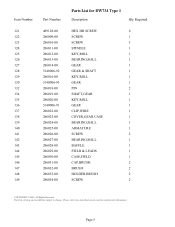
... List for current parts information. Please visit www.dewaltservicenet.com for DW734 Type 1 Description Qty Required DEFLECTOR,CHIP 1 SEAL,DUST 1 TRAY 1 SCREW 2 HANDLE 2 RING,RETAINING 4 TOP COVER 1 SCREW 4 HANDLE ASSY 1 SCREW 1 SWITCH,ON/OFF 1 SCREW 2 COVER,SWITCH 1 SCREW & WASHER 2 SCREW 4 WASHER,EX TOOTH 3 PLATE,SWITCH 1 HOUSING,SWITCH 1 PIN 3 PLATE 1 SEAL,DUST 1 BEARING,BALL 1 CASE,GEAR 1 RELIEF,STRAIN 1 CLAMP,CORD 1 CIRCUIT BREAKER 1 SCREW & WASHER 3 COPYRIGHT© 2005. Parts list, pricing, and availability subject to change...
... List for current parts information. Please visit www.dewaltservicenet.com for DW734 Type 1 Description Qty Required DEFLECTOR,CHIP 1 SEAL,DUST 1 TRAY 1 SCREW 2 HANDLE 2 RING,RETAINING 4 TOP COVER 1 SCREW 4 HANDLE ASSY 1 SCREW 1 SWITCH,ON/OFF 1 SCREW 2 COVER,SWITCH 1 SCREW & WASHER 2 SCREW 4 WASHER,EX TOOTH 3 PLATE,SWITCH 1 HOUSING,SWITCH 1 PIN 3 PLATE 1 SEAL,DUST 1 BEARING,BALL 1 CASE,GEAR 1 RELIEF,STRAIN 1 CLAMP,CORD 1 CIRCUIT BREAKER 1 SCREW & WASHER 3 COPYRIGHT© 2005. Parts list, pricing, and availability subject to change...
Parts Diagram
Page 6
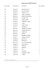
...-00 286032-00 286033-00 286034-00 Parts List for current parts information. Parts list, pricing, and availability subject to change. Please visit www.dewaltservicenet.com for DW734 Type 1 Description Qty Required HEX HD SCREW 6 SCREW 1 SCREW 3 SPINDLE 1 KEY,ROLL 1 BEARING,BALL 1 GEAR 1 GEAR & SHAFT 1 KEY,ROLL 1 GEAR 1 PIN 2 SHAFT,GEAR 1 KEY,ROLL 1 GEAR 1 CLIP,WIRE 1 COVER,GEAR CASE 1 BEARING,BALL 1 ARMATURE 1 SCREW 2 BEARING,BALL 1 BAFFLE 1 FIELD & LEADS 1 CASE,FIELD 1 CAP,BRUSH 2 BRUSH 2 HOLDER,BRUSH 2 SCREW 2 COPYRIGHT© 2005.
...-00 286032-00 286033-00 286034-00 Parts List for current parts information. Parts list, pricing, and availability subject to change. Please visit www.dewaltservicenet.com for DW734 Type 1 Description Qty Required HEX HD SCREW 6 SCREW 1 SCREW 3 SPINDLE 1 KEY,ROLL 1 BEARING,BALL 1 GEAR 1 GEAR & SHAFT 1 KEY,ROLL 1 GEAR 1 PIN 2 SHAFT,GEAR 1 KEY,ROLL 1 GEAR 1 CLIP,WIRE 1 COVER,GEAR CASE 1 BEARING,BALL 1 ARMATURE 1 SCREW 2 BEARING,BALL 1 BAFFLE 1 FIELD & LEADS 1 CASE,FIELD 1 CAP,BRUSH 2 BRUSH 2 HOLDER,BRUSH 2 SCREW 2 COPYRIGHT© 2005.
Parts Diagram
Page 7
Parts list, pricing, and availability subject to change. All Rights Reserved. Page 6 Please visit www.dewaltservicenet.com for DW734 Type 1 Description Qty Required MOTOR PULLEY 1 PLATE,DEWALT 1 CORD/9'/14-3 SJ 1 LABEL,WARNING 1 WRENCH,OPEN END 1 NAMEPLATE 1 LABEL,INSTR. 1 WARNING LABEL 1 LABEL 1 LABEL,FEED 1 TERMINAL 1 TERMINAL,FEMALE 5 TERMINAL,MALE 1 SCREW,M3 2 SPRING 1 RUBBER BUMPER 2 SCREW,TAPTITE 6 BRACKET 2 SPROCKET 1 VACUUM ADAPTOR 1 DUST HOOD 1 WRENCH 1 WRENCH 1 PIN 6 WASHER 4 WARNING LABEL 1 SCREW 3 COPYRIGHT©...
Parts list, pricing, and availability subject to change. All Rights Reserved. Page 6 Please visit www.dewaltservicenet.com for DW734 Type 1 Description Qty Required MOTOR PULLEY 1 PLATE,DEWALT 1 CORD/9'/14-3 SJ 1 LABEL,WARNING 1 WRENCH,OPEN END 1 NAMEPLATE 1 LABEL,INSTR. 1 WARNING LABEL 1 LABEL 1 LABEL,FEED 1 TERMINAL 1 TERMINAL,FEMALE 5 TERMINAL,MALE 1 SCREW,M3 2 SPRING 1 RUBBER BUMPER 2 SCREW,TAPTITE 6 BRACKET 2 SPROCKET 1 VACUUM ADAPTOR 1 DUST HOOD 1 WRENCH 1 WRENCH 1 PIN 6 WASHER 4 WARNING LABEL 1 SCREW 3 COPYRIGHT©...
Parts Diagram
Page 8
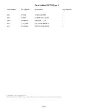
Page 7 Parts list, pricing, and availability subject to change. Please visit www.dewaltservicenet.com for DW734 Type 1 Description Qty Required TUBE GREASE 1 LUBRICANT-4LBS 1 GREASE.14 OZ. 1 SRT GAGE BLOCK 1 SRT 26LEAF GAGE 1 COPYRIGHT© 2005. All Rights Reserved. Item Number 800 800 800 836 836 Part Number 875914 875667 286445-00 233957-00 233801-00 Parts List for current parts information.
Page 7 Parts list, pricing, and availability subject to change. Please visit www.dewaltservicenet.com for DW734 Type 1 Description Qty Required TUBE GREASE 1 LUBRICANT-4LBS 1 GREASE.14 OZ. 1 SRT GAGE BLOCK 1 SRT 26LEAF GAGE 1 COPYRIGHT© 2005. All Rights Reserved. Item Number 800 800 800 836 836 Part Number 875914 875667 286445-00 233957-00 233801-00 Parts List for current parts information.


