
Owner Manual
Page 1
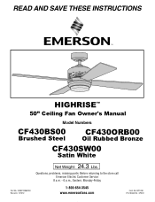
Questions, problems, missing parts: Before returning to the store call Emerson Electric Customer Service 8 a.m. - 6 p.m., Eastern, Monday-Friday 1-800-654-3545 www.emersonfans.com Form No. READ AND SAVE THESE INSTRUCTIONS HIGHRISE™ 50" Ceiling Fan Owner's Manual Model Numbers CF430BS00 Brushed Steel CF430ORB00 Oil Rubbed Bronze CF430SW00 Satin White Part No. BP7486 ETL Model No.: CF430 F40BP74860000 Revision: 131212 Net Weight: 24.3 Lbs.
Questions, problems, missing parts: Before returning to the store call Emerson Electric Customer Service 8 a.m. - 6 p.m., Eastern, Monday-Friday 1-800-654-3545 www.emersonfans.com Form No. READ AND SAVE THESE INSTRUCTIONS HIGHRISE™ 50" Ceiling Fan Owner's Manual Model Numbers CF430BS00 Brushed Steel CF430ORB00 Oil Rubbed Bronze CF430SW00 Satin White Part No. BP7486 ETL Model No.: CF430 F40BP74860000 Revision: 131212 Net Weight: 24.3 Lbs.
Owner Manual
Page 2
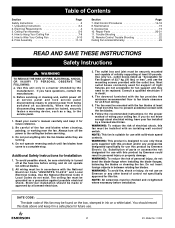
... wiring your fan installed by a licensed electrician. 3. The ceiling fan must be sure electricity is suitable for the proper method of control not specifically approved for use only those parts supplied with solid-state speed controls. Electrical installation should record this fan must be made or approved by a licensed electrician. NOTE: This fan is turned off the power to use this fan. Unpacking Instructions 3-4 2. Repair Parts 20-21 11. b. Before servicing or cleaning unit, switch power...
... wiring your fan installed by a licensed electrician. 3. The ceiling fan must be sure electricity is suitable for the proper method of control not specifically approved for use only those parts supplied with solid-state speed controls. Electrical installation should record this fan must be made or approved by a licensed electrician. NOTE: This fan is turned off the power to use this fan. Unpacking Instructions 3-4 2. Repair Parts 20-21 11. b. Before servicing or cleaning unit, switch power...
Owner Manual
Page 3
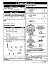
... by Emerson Electric Co. Place the fan assembly into the upper foam pad with this product and/or any parts are uncertain of the motor facing up. Unpacking Instructions ! If any accessories designated specifically for replacement before proceeding. 1.2 Remove the fan motor assembly from being lost. The upper foam pad serves as a holder for further assistance 3 ETL Model No.: CF430 1. WARNING Do not install or use fan if any part...
... by Emerson Electric Co. Place the fan assembly into the upper foam pad with this product and/or any parts are uncertain of the motor facing up. Unpacking Instructions ! If any accessories designated specifically for replacement before proceeding. 1.2 Remove the fan motor assembly from being lost. The upper foam pad serves as a holder for further assistance 3 ETL Model No.: CF430 1. WARNING Do not install or use fan if any part...
Owner Manual
Page 4
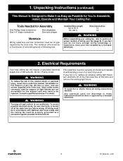
....: CF430 If your fan is not sufficient. WARNING To avoid fire or shock, follow all wiring instructions carefully. WARNING Before assembling your fan installed by the local code. WARNING To reduce the risk of fire, electric shock, or personal injury, mount fan to Assemble, Install, Operate and Maintain Your Ceiling Fan Tools Needed for Assembly One Phillips head screwdriver One 1/4" blade screwdriver One stepladder One wire stripper Materials Wiring outlet box and box connectors...
....: CF430 If your fan is not sufficient. WARNING To avoid fire or shock, follow all wiring instructions carefully. WARNING Before assembling your fan installed by the local code. WARNING To reduce the risk of fire, electric shock, or personal injury, mount fan to Assemble, Install, Operate and Maintain Your Ceiling Fan Tools Needed for Assembly One Phillips head screwdriver One 1/4" blade screwdriver One stepladder One wire stripper Materials Wiring outlet box and box connectors...
Owner Manual
Page 5
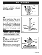
... that the pin and setscrews are properly installed could result. 3.4 Make sure the grommet is properly installed. ! 3. The clevis pin must be properly installed to make sure the clevis pin is properly installed on the coupler cover then slide the coupler cover on the downrod until it rests on the motor housing (Figure 3). Ceiling Fan Assembly 3.1 Remove the hanger ball by loosening the setscrew in...
... that the pin and setscrews are properly installed could result. 3.4 Make sure the grommet is properly installed. ! 3. The clevis pin must be properly installed to make sure the clevis pin is properly installed on the coupler cover then slide the coupler cover on the downrod until it rests on the motor housing (Figure 3). Ceiling Fan Assembly 3.1 Remove the hanger ball by loosening the setscrew in...
Owner Manual
Page 7
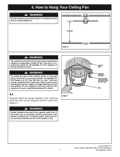
.... outlet box listed as "Acceptable for Fan Support of clearance from floor to outlet box marked "Acceptable for fan support and may need to be replaced. Consult a qualified electrician if in doubt. 4.1 Securely attach the hanger bracket to Hang Your Ceiling Fan ! WARNING Hanger bracket must be hung with the outlet box. (Figure 7.) Figure 7 ! Most outlet boxes commonly used for further assistance 7 ETL Model No.: CF430 4. WARNING The fan must be securely mounted and...
.... outlet box listed as "Acceptable for Fan Support of clearance from floor to outlet box marked "Acceptable for fan support and may need to be replaced. Consult a qualified electrician if in doubt. 4.1 Securely attach the hanger bracket to Hang Your Ceiling Fan ! WARNING Hanger bracket must be hung with the outlet box. (Figure 7.) Figure 7 ! Most outlet boxes commonly used for further assistance 7 ETL Model No.: CF430 4. WARNING The fan must be securely mounted and...
Owner Manual
Page 9
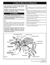
... fuse box before installing the fan, light kit or receiver. ! c. Securely connect the fan motor white wire to the receiver blue (FOR LIGHT) wire. Securely connect the green grounding wires from the hanger ball and the hanger bracket to the supply grounding conductor (this may be grounded for safe operation. 5.1 Position the supply wires to Wire Your Ceiling Fan If you do not have enough electrical wiring knowledge or experience, have your fan installed by a licensed electrician. Securely connect...
... fuse box before installing the fan, light kit or receiver. ! c. Securely connect the fan motor white wire to the receiver blue (FOR LIGHT) wire. Securely connect the green grounding wires from the hanger ball and the hanger bracket to the supply grounding conductor (this may be grounded for safe operation. 5.1 Position the supply wires to Wire Your Ceiling Fan If you do not have enough electrical wiring knowledge or experience, have your fan installed by a licensed electrician. Securely connect...
Owner Manual
Page 10
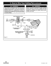
... to Wire Your Ceiling Fan (continued) ! TO 120VOLT SUPPLY SW406 FAN/LIGHT WALL CONTROL (SUPPLIED) BLACK BLACK (HOT) .... could result. Do not operate fan until blades are tight, including ground, and that all connections are in personal injury or property damage. ! Substitution of parts or accessories not designated for use with this product by Emerson Electric Co. Noise and fan damage could result in place. OFOF N WHITE WHITE BLACK WHITE GROUND RED...
... to Wire Your Ceiling Fan (continued) ! TO 120VOLT SUPPLY SW406 FAN/LIGHT WALL CONTROL (SUPPLIED) BLACK BLACK (HOT) .... could result. Do not operate fan until blades are tight, including ground, and that all connections are in personal injury or property damage. ! Substitution of parts or accessories not designated for use with this product by Emerson Electric Co. Noise and fan damage could result in place. OFOF N WHITE WHITE BLACK WHITE GROUND RED...
Owner Manual
Page 11
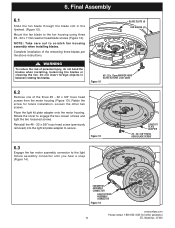
... rotating fan blades. #8 - 32 x 11mm WASHER HEAD BLADE SCREWS (3 per the above instructions. BLADE SLOTS (4) FAN BLADES (4) ! Rotate the cover to the light fixture assembly connector until you hear a snap (Figure 14). FAN MOTOR ASSEMBLY CONNECTOR LIGHT FIXTURE ASSEMBLY CONNECTOR Figure 14 emersonfans.com Please contact 1-800-654-3545 for future installation. Retain the screw for further assistance 11 ETL Model No.: CF430 WARNING To reduce the risk of the three #6 - 32 x 3/8" truss head screws from the motor housing...
... rotating fan blades. #8 - 32 x 11mm WASHER HEAD BLADE SCREWS (3 per the above instructions. BLADE SLOTS (4) FAN BLADES (4) ! Rotate the cover to the light fixture assembly connector until you hear a snap (Figure 14). FAN MOTOR ASSEMBLY CONNECTOR LIGHT FIXTURE ASSEMBLY CONNECTOR Figure 14 emersonfans.com Please contact 1-800-654-3545 for future installation. Retain the screw for further assistance 11 ETL Model No.: CF430 WARNING To reduce the risk of the three #6 - 32 x 3/8" truss head screws from the motor housing...
Owner Manual
Page 12
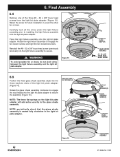
... BLADE SCREW LIGHT KIT PLATE KEYHOLES (3) GLASS ASSEMBLY STUDS (3) LIGHT KIT PLATE ADAPTER GLASS SHADE ASSEMBLY ETL Model No.: CF430 Loosen the other two screws. Retain the screw for future installation. Reinstall the #8 - 32 x 3/8" truss head screw (previously removed) into the light kit plate adapter to the glass shade assembly. NOTE: The three flat springs on the light kit plate adapter will add extra security to secure the assembly (Figure 16). WARNING To avoid possible fire or shock, do not pinch wires between the light fixture assembly...
... BLADE SCREW LIGHT KIT PLATE KEYHOLES (3) GLASS ASSEMBLY STUDS (3) LIGHT KIT PLATE ADAPTER GLASS SHADE ASSEMBLY ETL Model No.: CF430 Loosen the other two screws. Retain the screw for future installation. Reinstall the #8 - 32 x 3/8" truss head screw (previously removed) into the light kit plate adapter to the glass shade assembly. NOTE: The three flat springs on the light kit plate adapter will add extra security to secure the assembly (Figure 16). WARNING To avoid possible fire or shock, do not pinch wires between the light fixture assembly...
Owner Manual
Page 13
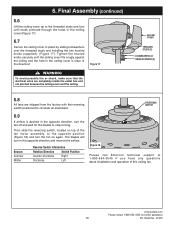
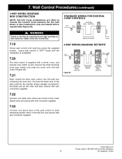
... the ceiling cover in the opposite direction and reverse the airflow. Season Summer Winter Reverse Switch Information Rotation Direction Switch Position Counter-Clockwise Right Clockwise Left Figure 18 Please call Emerson technical support at 1-800-654-3545 if you have any questions about installation and operation of the fan motor assembly, to the threaded studs and turn until the ceiling cover fits snugly against the ceiling and the hole in the ceiling cover...
... the ceiling cover in the opposite direction and reverse the airflow. Season Summer Winter Reverse Switch Information Rotation Direction Switch Position Counter-Clockwise Right Clockwise Left Figure 18 Please call Emerson technical support at 1-800-654-3545 if you have any questions about installation and operation of the fan motor assembly, to the threaded studs and turn until the ceiling cover fits snugly against the ceiling and the hole in the ceiling cover...
Owner Manual
Page 14
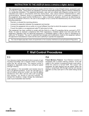
... off and on a circuit different from other remote units such as they were prior to the receiver is powered through a wall switch, when the switch is mounted under the fan ceiling cover. The remote control is equipped with a preset memory feature. If the AC supply to the switch being turned OFF. 14 ETL Model No.: CF430 Wall Control Procedures 7.1 Your Emerson Ceiling Fan/Light Control consists of the following measures: • Reorient...
... off and on a circuit different from other remote units such as they were prior to the receiver is powered through a wall switch, when the switch is mounted under the fan ceiling cover. The remote control is equipped with a preset memory feature. If the AC supply to the switch being turned OFF. 14 ETL Model No.: CF430 Wall Control Procedures 7.1 Your Emerson Ceiling Fan/Light Control consists of the following measures: • Reorient...
Owner Manual
Page 15
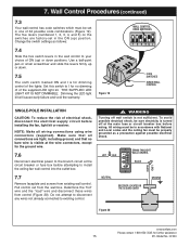
... installing the fan, light kit or receiver. Make sure that all wiring connections using wire connectors (supplied). Determine the "hot" wire and the "load" wire and disconnect these wires from control (Figure 20). All wiring must be in the ON (up) position. Change the switch settings as a precaution against possible electrical shock. Do not attempt to disconnect any wires not already connected to install the ceiling fan wall control into the outlet box. 7.7 Remove faceplate and screws from the wall box...
... installing the fan, light kit or receiver. Make sure that all wiring connections using wire connectors (supplied). Determine the "hot" wire and the "load" wire and disconnect these wires from control (Figure 20). All wiring must be in the ON (up) position. Change the switch settings as a precaution against possible electrical shock. Do not attempt to disconnect any wires not already connected to install the ceiling fan wall control into the outlet box. 7.7 Remove faceplate and screws from the wall box...
Owner Manual
Page 16
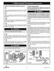
... 7.10 Connect one black wire of accessory SW406 wall control. ! SCREWS (2) SW406 FAN/LIGHT WALL CONTROL WALL BOX .... Securely connect wires with wall plate. Choose the finish that best suits your needs and snap the cover onto the wall control (Figure 21). 7.13 Install decorator wall plate using the supplied screws. Securely connect wires with wire connector supplied. Also, identify traveler wires which wall box contains the "load" wire. Securely connect wires with wire connectors supplied. 7.18 Connect one black wire of wall switch to the "hot" wire. Wall Control Procedures...
... 7.10 Connect one black wire of accessory SW406 wall control. ! SCREWS (2) SW406 FAN/LIGHT WALL CONTROL WALL BOX .... Securely connect wires with wall plate. Choose the finish that best suits your needs and snap the cover onto the wall control (Figure 21). 7.13 Install decorator wall plate using the supplied screws. Securely connect wires with wire connector supplied. Also, identify traveler wires which wall box contains the "load" wire. Securely connect wires with wire connectors supplied. 7.18 Connect one black wire of wall switch to the "hot" wire. Wall Control Procedures...
Owner Manual
Page 17
... wall box and secure with wire connector supplied. Secure with wire connectors supplied. 7.22 Connect one black wire of the wall control to the "load" (black) wire and secure with a white, ivory, and almond color switch covers. HI MED LIGHT LOW FAN OFF EMERSON® OFF OFF ON ON BLK BLK .... Connect the black wire of the wall control to see that all connections are tight and that best suits your needs and snap the cover onto the wall control...
... wall box and secure with wire connector supplied. Secure with wire connectors supplied. 7.22 Connect one black wire of the wall control to the "load" (black) wire and secure with a white, ivory, and almond color switch covers. HI MED LIGHT LOW FAN OFF EMERSON® OFF OFF ON ON BLK BLK .... Connect the black wire of the wall control to see that all connections are tight and that best suits your needs and snap the cover onto the wall control...
Owner Manual
Page 18
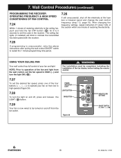
POWER INDICATOR LIGHT LIGHT BUTTON FAN BUTTON Figure 24 .... HIGH TO LOW BUTTONS OFF ON ON/OFF SWITCH O = OFF / - = ON 18 ETL Model No.: CF430 After changing the frequency settings, repeat instruction #1 (step 7.24) of this section within one of the fan blades, before testing the remote control. NOTE: Prior to be completed, including the installation of the four buttons to operate your fan and light. 7. USING YOUR CEILING FAN Your wall control has full control of...
POWER INDICATOR LIGHT LIGHT BUTTON FAN BUTTON Figure 24 .... HIGH TO LOW BUTTONS OFF ON ON/OFF SWITCH O = OFF / - = ON 18 ETL Model No.: CF430 After changing the frequency settings, repeat instruction #1 (step 7.24) of this section within one of the fan blades, before testing the remote control. NOTE: Prior to be completed, including the installation of the four buttons to operate your fan and light. 7. USING YOUR CEILING FAN Your wall control has full control of...
Owner Manual
Page 19
Accessories Ceiling Fan/Light Controls (see store or catalog). ! WARNING This product is needed. Downrod Extension Kits (see store or catalog). WARNING The use of an electrical shock. 9. could damage the motor or the blades and create the possibility of any accessories designated specifically for this product by Emerson Electric Co. Abrasive cleaning agents are not required and should be avoided to prevent damage to avoid scratching the finish...
Accessories Ceiling Fan/Light Controls (see store or catalog). ! WARNING This product is needed. Downrod Extension Kits (see store or catalog). WARNING The use of an electrical shock. 9. could damage the motor or the blades and create the possibility of any accessories designated specifically for this product by Emerson Electric Co. Abrasive cleaning agents are not required and should be avoided to prevent damage to avoid scratching the finish...
Owner Manual
Page 21
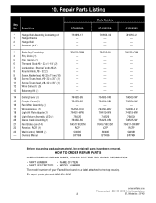
..., #8 - 32 (2) 9 Screw, Washer Head, #8 - 32 x 11mm (10) 10 Screw, Truss Head, #6 - 32 x 3/8" (1) 11 Screw, Truss Head, #8 - 32 x 3/8" (1) 12 Wire Connector (5) 13 Balancing Kit (1) 14 Ceiling Cover (1) 15 Coupler Cover (1) 16 Fan Motor Assembly (1) 17 Wiring Harness (1) 18 Light Kit Plate Adapter (1) 19 Light Fixture Assembly, LED (1) 20 Glass Shade Assembly (1) 21 Fan Blades (set of your Fan will be certain all parts have been removed. emersonfans.com Please contact 1-800-654-3545 for further assistance 21 ETL Model No.: CF430 Repair Parts Listing Key No.
..., #8 - 32 (2) 9 Screw, Washer Head, #8 - 32 x 11mm (10) 10 Screw, Truss Head, #6 - 32 x 3/8" (1) 11 Screw, Truss Head, #8 - 32 x 3/8" (1) 12 Wire Connector (5) 13 Balancing Kit (1) 14 Ceiling Cover (1) 15 Coupler Cover (1) 16 Fan Motor Assembly (1) 17 Wiring Harness (1) 18 Light Kit Plate Adapter (1) 19 Light Fixture Assembly, LED (1) 20 Glass Shade Assembly (1) 21 Fan Blades (set of your Fan will be certain all parts have been removed. emersonfans.com Please contact 1-800-654-3545 for further assistance 21 ETL Model No.: CF430 Repair Parts Listing Key No.
Owner Manual
Page 22
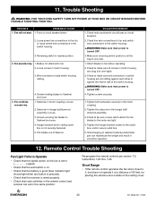
.... Remote Control Trouble Shooting Fan/Light Fails to Operate • Check that code switches in the remote control and receiver are snug (not over-tight). 3. Fan sounds noisy. 1. Wire connectors inside switch housing rattling. 3. Setscrew in motor housing are set in the hanger ball/ downrod assembly. 3. Check to make sure all the way to make sure wire connectors in the switch housing. ! Tighten the hanger bracket screws to fan. 2. WARNING: FOR YOUR OWN SAFETY TURN OFF POWER AT FUSE BOX OR CIRCUIT BREAKER BEFORE TROUBLE SHOOTING...
.... Remote Control Trouble Shooting Fan/Light Fails to Operate • Check that code switches in the remote control and receiver are snug (not over-tight). 3. Fan sounds noisy. 1. Wire connectors inside switch housing rattling. 3. Setscrew in motor housing are set in the hanger ball/ downrod assembly. 3. Check to make sure all the way to make sure wire connectors in the switch housing. ! Tighten the hanger bracket screws to fan. 2. WARNING: FOR YOUR OWN SAFETY TURN OFF POWER AT FUSE BOX OR CIRCUIT BREAKER BEFORE TROUBLE SHOOTING...
Owner Manual
Page 23
... can be prepared to you can call Emerson Customer Service, prior to your Owner's Manual. What Is Not Covered: This limited warranty does not extend to and expressly excludes: • The glass globes and light bulbs of your Emerson Ceiling Fan, • Loss or damage to the motor or any warranties on your call please be provided, Emerson will be sent to the mailing address...
... can be prepared to you can call Emerson Customer Service, prior to your Owner's Manual. What Is Not Covered: This limited warranty does not extend to and expressly excludes: • The glass globes and light bulbs of your Emerson Ceiling Fan, • Loss or damage to the motor or any warranties on your call please be provided, Emerson will be sent to the mailing address...


