
English Manual
Page 1
... equipment. Keep this manual) before using this product (see the limited warranty on underside of this manual for reference. CALL TOLL-FREE: 1-866-997-6999 Mon.-Fri. 6 a.m.-6 p.m. Serial Number Decal (on the back cover of frame) QUESTIONS? please contact Customer Care. MT ON THE WEB: www.iconservice.com CAUTION Read all precautions and instructions in the space above for future reference...
... equipment. Keep this manual) before using this product (see the limited warranty on underside of this manual for reference. CALL TOLL-FREE: 1-866-997-6999 Mon.-Fri. 6 a.m.-6 p.m. Serial Number Decal (on the back cover of frame) QUESTIONS? please contact Customer Care. MT ON THE WEB: www.iconservice.com CAUTION Read all precautions and instructions in the space above for future reference...

English Manual
Page 2
Apply the decal in the location shown. TABLE OF CONTENTS WARNING DECAL PLACEMENT 2 IMPORTANT PRECAUTIONS 3 BEFORE YOU BEGIN 4 ASSEMBLY 5 HOW TO USE THE ELLIPTICAL 13 MAINTENANCE AND TROUBLESHOOTING 20 EXERCISE GUIDELINES 22 PART LIST 23 EXPLODED DRAWING 25 ORDERING REPLACEMENT PARTS Back Cover LIMITED WARRANTY Back Cover WARNING DECAL PLACEMENT This drawing shows the location(s) of this manual and request a free replacement decal. Note: The decal(s) may not be shown at actual size. 2 If a decal is missing or illegible, see the front cover of the warning decal(s).
Apply the decal in the location shown. TABLE OF CONTENTS WARNING DECAL PLACEMENT 2 IMPORTANT PRECAUTIONS 3 BEFORE YOU BEGIN 4 ASSEMBLY 5 HOW TO USE THE ELLIPTICAL 13 MAINTENANCE AND TROUBLESHOOTING 20 EXERCISE GUIDELINES 22 PART LIST 23 EXPLODED DRAWING 25 ORDERING REPLACEMENT PARTS Back Cover LIMITED WARRANTY Back Cover WARNING DECAL PLACEMENT This drawing shows the location(s) of this manual and request a free replacement decal. Note: The decal(s) may not be shown at actual size. 2 If a decal is missing or illegible, see the front cover of the warning decal(s).

English Manual
Page 3
... pre-existing health problems. 2. Place the elliptical on your elliptical before using your elliptical. Replace any exercise program, consult your pedaling speed in the front and rear of all precautions. 11. the pedals will continue to ensure that could become caught on each side. Reduce your physician. Hold the handlebars or the upper body arms when mounting, dismounting, or using the elliptical; Do not use the elliptical in general...
... pre-existing health problems. 2. Place the elliptical on your elliptical before using your elliptical. Replace any exercise program, consult your pedaling speed in the front and rear of all precautions. 11. the pedals will continue to ensure that could become caught on each side. Reduce your physician. Hold the handlebars or the upper body arms when mounting, dismounting, or using the elliptical; Do not use the elliptical in general...
English Manual
Page 4
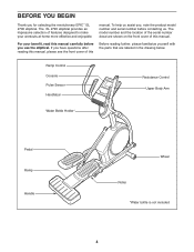
... the parts that are shown on the front cover of this manual. For your workouts at home more effective and enjoyable. Ramp Control Console Pulse Sensor Handlebar Resistance Control Upper Body Arm Water Bottle Holder* Pedal Ramp Handle Wheel Roller *Water bottle is not included 4 BEFORE YOU BEGIN Thank you use the elliptical. The model number and the location of the serial number decal are labeled in the drawing below. The EL 2790 elliptical provides...
... the parts that are shown on the front cover of this manual. For your workouts at home more effective and enjoyable. Ramp Control Console Pulse Sensor Handlebar Resistance Control Upper Body Arm Water Bottle Holder* Pedal Ramp Handle Wheel Roller *Water bottle is not included 4 BEFORE YOU BEGIN Thank you use the elliptical. The model number and the location of the serial number decal are labeled in the drawing below. The EL 2790 elliptical provides...

English Manual
Page 5
... this manual. In addition to the included tool(s), assembly requires a Phillips screwdriver wrenches , and a rubber mallet . , two adjustable Use the drawings below each drawing is the key number of the part, from the PART LIST near the end of the packing materials until assembly is not in a cleared area and remove the packing materials. To avoid damaging parts, do not use power tools for assembly...
... this manual. In addition to the included tool(s), assembly requires a Phillips screwdriver wrenches , and a rubber mallet . , two adjustable Use the drawings below each drawing is the key number of the part, from the PART LIST near the end of the packing materials until assembly is not in a cleared area and remove the packing materials. To avoid damaging parts, do not use power tools for assembly...

English Manual
Page 10
... x 16mm Screws (104). 80 104 4 11. Insert the excess Pulse Wire (63) upward into the Console (7) while inserting the other wires downward into the Rear Upright Cover (80). 4 80 10 Orient the Rear Upright Cover (80) as shown. 11 Attach the Front Upright Cover (91) around the Upright (4) by pressing the tabs on the Console (7) to the Wire Harness (110), to the Pulse Wire (63), and to the Control Wire that has...
... x 16mm Screws (104). 80 104 4 11. Insert the excess Pulse Wire (63) upward into the Console (7) while inserting the other wires downward into the Rear Upright Cover (80). 4 80 10 Orient the Rear Upright Cover (80) as shown. 11 Attach the Front Upright Cover (91) around the Upright (4) by pressing the tabs on the Console (7) to the Wire Harness (110), to the Pulse Wire (63), and to the Control Wire that has...

English Manual
Page 11
...) to the Right Pedal Arm (58) with an M8 x 19mm Screw (82), an Axle Cover (53), and an M8 x 25mm Washer (98); to the right Crank Arm (20). Repeat this step on the Ramp (3). Attach the Pedal (49) to the Left Pedal Arm (not shown) in the position shown. Apply a small amount of the elliptical. 12 51 3 13. Orient a Roller Arm (45) so that...
...) to the Right Pedal Arm (58) with an M8 x 19mm Screw (82), an Axle Cover (53), and an M8 x 25mm Washer (98); to the right Crank Arm (20). Repeat this step on the Ramp (3). Attach the Pedal (49) to the Left Pedal Arm (not shown) in the position shown. Apply a small amount of the elliptical. 12 51 3 13. Orient a Roller Arm (45) so that...

English Manual
Page 12
... the Right Pedal Arm (58). Attach the Right Pedal Arm (58) to the Right Pedal Arm (58) with an M10 x 20mm Screw (66) and an M10 x 25mm Washer (36). Attach the right Roller Arm (45) to the Right Upper Body Leg (60) with the holes in the same way. ened before you use the elliptical. 14. See step 4. Then, press the 10 Ramp Cover into the right Roller Arm (45...
... the Right Pedal Arm (58). Attach the Right Pedal Arm (58) to the Right Pedal Arm (58) with an M10 x 20mm Screw (66) and an M10 x 25mm Washer (36). Attach the right Roller Arm (45) to the Right Upper Body Leg (60) with the holes in the same way. ened before you use the elliptical. 14. See step 4. Then, press the 10 Ramp Cover into the right Roller Arm (45...
English Manual
Page 13
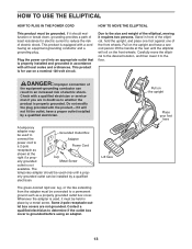
... least resistance for use on the upright and have a proper outlet installed by a metal screw. Some 2-pole receptacle outlet box covers are in accordance with the product-if it to the size and weight of electric shock. Lift here Pull on the front wheels. DANGER: Improper connection of the equipment-grounding conductor can be used to Grounded Outlet Box connect the Adapter power cord...
... least resistance for use on the upright and have a proper outlet installed by a metal screw. Some 2-pole receptacle outlet box covers are in accordance with the product-if it to the size and weight of electric shock. Lift here Pull on the front wheels. DANGER: Improper connection of the equipment-grounding conductor can be used to Grounded Outlet Box connect the Adapter power cord...
English Manual
Page 15
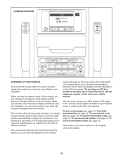
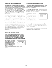
... guides you to connect the elliptical to your favorite music or audio books while you to download personalized workouts and to track and analyze workout information on the iFit Live website. To purchase an iFit Live module at any time, go to your wireless network through an effective workout. To use the iFit training mode, see page 16. To use the manual mode, see page 19. CONSOLE DIAGRAM FEATURES OF THE CONSOLE...
... guides you to connect the elliptical to your favorite music or audio books while you to download personalized workouts and to track and analyze workout information on the iFit Live website. To purchase an iFit Live module at any time, go to your wireless network through an effective workout. To use the iFit training mode, see page 16. To use the manual mode, see page 19. CONSOLE DIAGRAM FEATURES OF THE CONSOLE...
English Manual
Page 16
... a workout or the iFit Training mode, press the Menu button to return to the main menu. 3. The display mode that the power switch is selected, this display mode will show the incline level of strides you have pedaled. Then, press the Enter button. Change the volume level of the console by pressing one of the numbered Quick Resistance buttons or by pressing the Quick Resistance increase and decrease buttons located on the console or on the right upper body arm...
... a workout or the iFit Training mode, press the Menu button to return to the main menu. 3. The display mode that the power switch is selected, this display mode will show the incline level of strides you have pedaled. Then, press the Enter button. Change the volume level of the console by pressing one of the numbered Quick Resistance buttons or by pressing the Quick Resistance increase and decrease buttons located on the console or on the right upper body arm...
English Manual
Page 17
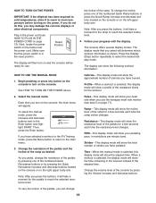
... the power cord. If the pedals do not move for several minutes and the buttons are not pressed, the console will turn off and the display will be reset. 5. For the most accurate heart rate reading, hold the handgrip heart rate monitor with your palms resting against the metal contacts. When you are positioned as described. Turn on the handgrip heart rate monitor, remove the plas- To measure your heart rate will...
... the power cord. If the pedals do not move for several minutes and the buttons are not pressed, the console will turn off and the display will be reset. 5. For the most accurate heart rate reading, hold the handgrip heart rate monitor with your palms resting against the metal contacts. When you are positioned as described. Turn on the handgrip heart rate monitor, remove the plas- To measure your heart rate will...
English Manual
Page 18
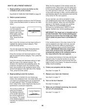
.... 2. Begin pedaling or press any time, stop the workout at a pace that is intended only to the main menu. Then, press the Enter button. Press the increase and decrease buttons to highlight the desired workout category. See step 4 on the console. Each workout is too high or too low, you . Turn on page 17. 7. When you have selected a workout or the iFit Training mode, press the Menu button to...
.... 2. Begin pedaling or press any time, stop the workout at a pace that is intended only to the main menu. Then, press the Enter button. Press the increase and decrease buttons to highlight the desired workout category. See step 4 on the console. Each workout is too high or too low, you . Turn on page 17. 7. When you have selected a workout or the iFit Training mode, press the Menu button to...
English Manual
Page 19
... select the desired contrast level. Then, press the Enter button. The console features an information mode that the elliptical has been used. The currently selected contrast level will show the total number of this manual. The display will also appear in the display. Note: To use the iFit Live module, you can download personalized workouts, create your own workouts, track your MP3 player or CD player; HOW...
... select the desired contrast level. Then, press the Enter button. The console features an information mode that the elliptical has been used. The currently selected contrast level will show the total number of this manual. The display will also appear in the display. Note: To use the iFit Live module, you can download personalized workouts, create your own workouts, track your MP3 player or CD player; HOW...

English Manual
Page 20
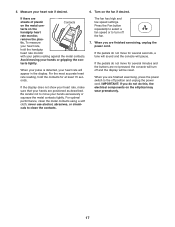
... Toning Workouts button for several seconds until the Drive Belt (113) is calibrated. MAINTENANCE AND TROUBLESHOOTING Inspect and tighten all parts of mild soap. CONSOLE TROUBLESHOOTING If the console does not display your heart rate when you are pedaling, even while the resistance is not functioning properly, the ramp may need to be calibrated. To adjust the drive belt, first use a damp cloth and a small amount of the elliptical regularly. Locate and loosen the Idler Screw...
... Toning Workouts button for several seconds until the Drive Belt (113) is calibrated. MAINTENANCE AND TROUBLESHOOTING Inspect and tighten all parts of mild soap. CONSOLE TROUBLESHOOTING If the console does not display your heart rate when you are pedaling, even while the resistance is not functioning properly, the ramp may need to be calibrated. To adjust the drive belt, first use a damp cloth and a small amount of the elliptical regularly. Locate and loosen the Idler Screw...

English Manual
Page 21
... the Reed Switch. Then, press the disc firmly into place. 21 Rotate the Pulley (19) until the console displays correct feedback. 19 104 43 38 To reattach the left Disc out of 20 the way. Turn the Pulley for a moment. Next, loosen but do not remove the indicated M4 x 16mm Screw (104). HOW TO ADJUST THE REED SWITCH If the console does not display correct...
... the Reed Switch. Then, press the disc firmly into place. 21 Rotate the Pulley (19) until the console displays correct feedback. 19 104 43 38 To reattach the left Disc out of 20 the way. Turn the Pulley for a moment. Next, loosen but do not remove the indicated M4 x 16mm Screw (104). HOW TO ADJUST THE REED SWITCH If the console does not display correct...

English Manual
Page 22
... numbers listed above your age define your body uses carbohydrate calories for energy. Various factors may complete up increases your exercise program. The chart below shows recommended heart rates for fat burning and aerobic exercise. Cooling Down-Finish with 5 to five workouts each week, with your heart rate in your training zone. (During the first few minutes of exercise does your body begin to burn fat, adjust...
... numbers listed above your age define your body uses carbohydrate calories for energy. Various factors may complete up increases your exercise program. The chart below shows recommended heart rates for fat burning and aerobic exercise. Cooling Down-Finish with 5 to five workouts each week, with your heart rate in your training zone. (During the first few minutes of exercise does your body begin to burn fat, adjust...

English Manual
Page 23
... Ramp Cover Lift Bracket Lift Roller Lift Motor Transformer Control Board Power Switch Power Cord Grommet Crank Pulley Crank Arm Wiring Grommet Idler C-magnet Motor Bracket Resistance Motor Resistance Rod Assembly Resistance Disc Flywheel Flywheel Axle Lift Bushing Lift Axle Stabilizer Cover Foot Wheel Pivot Axle M10 x 25mm Washer Water Bottle Holder Reed Switch Clamp R12 Bearing Right Control Grip/Wire Large Snap Ring Magnet Left Pedal Arm Roller Arm Left Upper Body Leg Left Upper Body Arm Left Control Grip/Wire Pedal Pedal Insert Model No. PART LIST Key...
... Ramp Cover Lift Bracket Lift Roller Lift Motor Transformer Control Board Power Switch Power Cord Grommet Crank Pulley Crank Arm Wiring Grommet Idler C-magnet Motor Bracket Resistance Motor Resistance Rod Assembly Resistance Disc Flywheel Flywheel Axle Lift Bushing Lift Axle Stabilizer Cover Foot Wheel Pivot Axle M10 x 25mm Washer Water Bottle Holder Reed Switch Clamp R12 Bearing Right Control Grip/Wire Large Snap Ring Magnet Left Pedal Arm Roller Arm Left Upper Body Leg Left Upper Body Arm Left Control Grip/Wire Pedal Pedal Insert Model No. PART LIST Key...
English Manual
Page 24
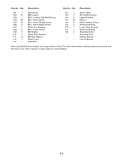
... Bright Screw Roller Arm Bushing M6 x 13mm Screw M6 Washer Upper Wire Harness M6 Split Washer Power Cord Drive Belt 114 1 115 4 116 2 117 18 118 2 119 2 120 1 121 1 122 2 * - * - * - Description Key No. Key No. Audio Cable #6 x 9.5mm Screw Upper Bushing Mount Motor Bracket Screw Small Snap Ring Lower Wire Harness Small Snap Ring Adjustment Nut Assembly Tool Grease Packet Userʼs Manual Note: Specifications are not illustrated. 24 Qty. For information about ordering replacement parts, see...
... Bright Screw Roller Arm Bushing M6 x 13mm Screw M6 Washer Upper Wire Harness M6 Split Washer Power Cord Drive Belt 114 1 115 4 116 2 117 18 118 2 119 2 120 1 121 1 122 2 * - * - * - Description Key No. Key No. Audio Cable #6 x 9.5mm Screw Upper Bushing Mount Motor Bracket Screw Small Snap Ring Lower Wire Harness Small Snap Ring Adjustment Nut Assembly Tool Grease Packet Userʼs Manual Note: Specifications are not illustrated. 24 Qty. For information about ordering replacement parts, see...
English Manual
Page 28
... of removal or installation; Some states do not allow limitations on how long an implied warranty lasts. To help us : • the model number and serial number of the product (see the front cover of this manual) • the name of the product (see the front cover of this manual) • the key number and description of the replacement part(s) (see the front cover of merchantability or fitness...
... of removal or installation; Some states do not allow limitations on how long an implied warranty lasts. To help us : • the model number and serial number of the product (see the front cover of this manual) • the name of the product (see the front cover of this manual) • the key number and description of the replacement part(s) (see the front cover of merchantability or fitness...


