

Owners Manual
Page 3
... 34.0 cm 93.0 cm P.O. BOX 4137 • 1300 EAST VALENCIA DRIVE • FULLERTON, CALIFORNIA 92634 NOTE: See accompanying limited warranty folder System Metric System U.S. • MA6 MIXER AMPLIFIER OPERATION INSTRUCTION MANUAL BY d MADE IN U.S.A.iSts°1.° • it141 zittl;id . PHYSICAL DIMENSIONS (APPROXIMATE, FOR SHIPPING PURPOSES) MIXER AMPLIFIER SPEAKER COLUMN U.S.
... 34.0 cm 93.0 cm P.O. BOX 4137 • 1300 EAST VALENCIA DRIVE • FULLERTON, CALIFORNIA 92634 NOTE: See accompanying limited warranty folder System Metric System U.S. • MA6 MIXER AMPLIFIER OPERATION INSTRUCTION MANUAL BY d MADE IN U.S.A.iSts°1.° • it141 zittl;id . PHYSICAL DIMENSIONS (APPROXIMATE, FOR SHIPPING PURPOSES) MIXER AMPLIFIER SPEAKER COLUMN U.S.
Owners Manual
Page 5
... 7 1 Power On/Off Switch 7 1 Speaker Output 7 1 Speaker Fuse 7 1 Accessory AC Outlet 7 3 3 Line Cord Receptable Circuit Breaker 7 7 3 SECTION II 3 Setting Up The System 8 3 Speaker Placement 8 3 Speaker Connection 8 3 Microphones 8 3 AC Power Cord 8 3 Preliminary Control Settings 9 5 Final Control Adjustments 9 5 Volume 9 5 Tone 9 5 Master Section Reverb Return and Effects 5 Return Switches 9 5 Emphasizing One Instrument on 5 the Monitor...
... 7 1 Power On/Off Switch 7 1 Speaker Output 7 1 Speaker Fuse 7 1 Accessory AC Outlet 7 3 3 Line Cord Receptable Circuit Breaker 7 7 3 SECTION II 3 Setting Up The System 8 3 Speaker Placement 8 3 Speaker Connection 8 3 Microphones 8 3 AC Power Cord 8 3 Preliminary Control Settings 9 5 Final Control Adjustments 9 5 Volume 9 5 Tone 9 5 Master Section Reverb Return and Effects 5 Return Switches 9 5 Emphasizing One Instrument on 5 the Monitor...

Owners Manual
Page 6
... Response Curves 9 Master Section Effects, Direct Inputs, Reverb Jacks • 6 6 10 Rear Panel 7 11 Typical Stage Setup 8 12 Speaker Connections 8 13 Effects Jack Connections 10 15 Typical Speaker, Monitor, and Tape Recording Connections 11 16 MA6 System with Auxiliary and Monitor Speakers 11 17 Bi-Amp Connections 12 18 Tape Recording 12...
... Response Curves 9 Master Section Effects, Direct Inputs, Reverb Jacks • 6 6 10 Rear Panel 7 11 Typical Stage Setup 8 12 Speaker Connections 8 13 Effects Jack Connections 10 15 Typical Speaker, Monitor, and Tape Recording Connections 11 16 MA6 System with Auxiliary and Monitor Speakers 11 17 Bi-Amp Connections 12 18 Tape Recording 12...
Owners Manual
Page 7
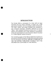
...a Thiele aligned vented enclosure. BEFORE ATTEMPTING TO USE THE SYSTEM, FAMILIARIZE YOURSELF WITH THE INFORMATION CONTAINED IN THIS MANUAL. • • INTRODUCTION The Fender MA6 is composed of the various controls and jacks (in total, the unit has 55 controls and 24 connectors and ...jacks). Each speaker enclosure contains two 12" special design cone speakers and a high frequency compression • driver with six input channels and...
...a Thiele aligned vented enclosure. BEFORE ATTEMPTING TO USE THE SYSTEM, FAMILIARIZE YOURSELF WITH THE INFORMATION CONTAINED IN THIS MANUAL. • • INTRODUCTION The Fender MA6 is composed of the various controls and jacks (in total, the unit has 55 controls and 24 connectors and ...jacks). Each speaker enclosure contains two 12" special design cone speakers and a high frequency compression • driver with six input channels and...

Owners Manual
Page 8
Although only one channel of six) Block Diagram See Figure 4 for the par- Normally, once the Gain Control has been set . Item 1) This adjusts the gain of the microphone preamplifier, allowing adjustment of the input signal. ticular input source to -noise ratio for frequency... 1) and the Master Control (Fig. 2). The gain control affects both the Main and the Monitor mixes. Item 6) is just flickering, the control is properly set , it will not need to be turned down until the light just flickers, to avoid audible distortion. INPUT CHANNEL CONTROL FUNCTIONS Gain Control (Fig. 3 -...
Although only one channel of six) Block Diagram See Figure 4 for the par- Normally, once the Gain Control has been set . Item 1) This adjusts the gain of the microphone preamplifier, allowing adjustment of the input signal. ticular input source to -noise ratio for frequency... 1) and the Master Control (Fig. 2). The gain control affects both the Main and the Monitor mixes. Item 6) is just flickering, the control is properly set , it will not need to be turned down until the light just flickers, to avoid audible distortion. INPUT CHANNEL CONTROL FUNCTIONS Gain Control (Fig. 3 -...
Owners Manual
Page 13
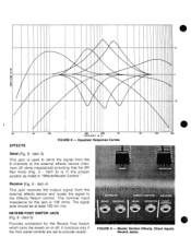
.... 3 - The nominal input impedance for the Reverb Foot Switch which turns the reverb on or off. It functions only if the front panel controls are set to provide reverb. ,EifECTS CEJVE VERB OOT rrcti FIGURE 9 - Master Section Effects, Direct Inputs, Reverb Jacks +10 AMPLITUDE IN dB 0 10 5 20 50 EFFECTS 100...
.... 3 - The nominal input impedance for the Reverb Foot Switch which turns the reverb on or off. It functions only if the front panel controls are set to provide reverb. ,EifECTS CEJVE VERB OOT rrcti FIGURE 9 - Master Section Effects, Direct Inputs, Reverb Jacks +10 AMPLITUDE IN dB 0 10 5 20 50 EFFECTS 100...
Owners Manual
Page 14
... for use in the event of internal amplifier failure. Item 7) Two jacks wired in the mixer cover for connection of the speakers should not be replaced only with the speaker jacks. Total impedance of the speaker systems to the Mixer, disconnecting the internal reverb unit. Item 10) Connection for the detachable...
... for use in the event of internal amplifier failure. Item 7) Two jacks wired in the mixer cover for connection of the speakers should not be replaced only with the speaker jacks. Total impedance of the speaker systems to the Mixer, disconnecting the internal reverb unit. Item 10) Connection for the detachable...

Owners Manual
Page 15
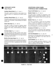
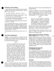
... with no damage to two-prong adapter. Item 2). Item 10). If necessary, use of volume. E STANDARD SPEAKER CONNECTION NO. 1 FROM SPEAKER JACK (1) MA6 MIXER S P A K STANDARD SPEAKER CONNECTION NO. 2 • FIGURE 12 - An accessory AC outlet (Fig. 10 - The use a three-prong to...the microphones (Fig. 11) will cause a loss of shielded guitar cords for speaker connections. Typical Stage Setup FROM SPEAKER 12) JACKS os P E A MA6 A K MIXER K. • SECTION II SETTING UP THE SYSTEM Speaker Placement Placing the speakers forward of the Mixer, marked "Speaker."
... with no damage to two-prong adapter. Item 2). Item 10). If necessary, use of volume. E STANDARD SPEAKER CONNECTION NO. 1 FROM SPEAKER JACK (1) MA6 MIXER S P A K STANDARD SPEAKER CONNECTION NO. 2 • FIGURE 12 - An accessory AC outlet (Fig. 10 - The use a three-prong to...the microphones (Fig. 11) will cause a loss of shielded guitar cords for speaker connections. Typical Stage Setup FROM SPEAKER 12) JACKS os P E A MA6 A K MIXER K. • SECTION II SETTING UP THE SYSTEM Speaker Placement Placing the speakers forward of the Mixer, marked "Speaker."
Owners Manual
Page 16
...Fig. 6 - Item 8). Item 6) to the full clockwise position. Equalizers The MA6 has two 5-band graphic equalizers (Fig. 7 Item 1 and 2) one for the Main speakers and one of the overload warning light. Set both the Main and Monitor speakers. If the VU Meter does not light up of... 8). 7. Set all Channel, Main, and Monitor Level controls ("faders") to feedback or ring. Item 3) (Fig. 6 - Turn Gain controls to almost the "off in , switches the internal (or external, if used to adjust the tonal quality to suit the acoustics of the MA6 P.A. These equalizers are producing ...
...Fig. 6 - Item 8). Item 6) to the full clockwise position. Equalizers The MA6 has two 5-band graphic equalizers (Fig. 7 Item 1 and 2) one for the Main speakers and one of the overload warning light. Set both the Main and Monitor speakers. If the VU Meter does not light up of... 8). 7. Set all Channel, Main, and Monitor Level controls ("faders") to feedback or ring. Item 3) (Fig. 6 - Turn Gain controls to almost the "off in , switches the internal (or external, if used to adjust the tonal quality to suit the acoustics of the MA6 P.A. These equalizers are producing ...

Owners Manual
Page 17
... can be connected to be used as the master unit, connect the Main channel output of an Additional Mixer (Fig. 13) The Fender MA6 can also be used for several functions. Important vocal range. Sometimes cutting 2 kHz slightly can also be used for the Monitor speakers. MONITOR...System to an external power amp for tape recording (Fig. 15). If they are required, this control adds presence or better definition of the MA6 as "cleaning up" the vocals by minimizing bass frequencies from a miked acoustic guitar, as well as Submasters. Effects Jack Connections Maximum shelf ...
... can be connected to be used as the master unit, connect the Main channel output of an Additional Mixer (Fig. 13) The Fender MA6 can also be used for several functions. Important vocal range. Sometimes cutting 2 kHz slightly can also be used for the Monitor speakers. MONITOR...System to an external power amp for tape recording (Fig. 15). If they are required, this control adds presence or better definition of the MA6 as "cleaning up" the vocals by minimizing bass frequencies from a miked acoustic guitar, as well as Submasters. Effects Jack Connections Maximum shelf ...

Owners Manual
Page 18
...crossover, and connect the "high" output of the additional Power Amp. • Bi-Amping with an additional P.A. MA6 System with the same type. To record the main channel signal, connect the tape recorder to the additional P.A. amplifier... To play back pre-recorded tapes, connect the tape recorder to the Effects Receive jack (Fig. 9 - Item 1 and 2) or to one of less than 4 ohms. Replace the fuse only with Auxiliary and Monitor Speakers MAIN SPEAKERS AUXILIARY M S A P 6 E A K E R U M S A P 6 E A K E R H POWER AMP 'PRE AMP "SPEAKER" OUT" OUT "MONITOR OUT" A' S...
...crossover, and connect the "high" output of the additional Power Amp. • Bi-Amping with an additional P.A. MA6 System with the same type. To record the main channel signal, connect the tape recorder to the additional P.A. amplifier... To play back pre-recorded tapes, connect the tape recorder to the Effects Receive jack (Fig. 9 - Item 1 and 2) or to one of less than 4 ohms. Replace the fuse only with Auxiliary and Monitor Speakers MAIN SPEAKERS AUXILIARY M S A P 6 E A K E R U M S A P 6 E A K E R H POWER AMP 'PRE AMP "SPEAKER" OUT" OUT "MONITOR OUT" A' S...

Owners Manual
Page 19
AMP OUT T J "MONITOR OUT" POWER AMP MONITOR SPEAKER MAS MIXER MONITOR SPEAKER FIGURE 17 - Bi-Amp Connections • **No S P E A K E R H TAPE RECORDER • 110--..111 S P "SPEAKER" E K "PRE AMP OUT" MA6 MIXER H -MONITOR OUT" POWER AMP MONITOR SPEAKER MONITOR SPEAKER FIGURE 18 - Tape Recording • SPEAKER (HIGH) SPEAKER (HIGH) SPEAKER (LOW) SPEAKER "POWER AMP IN" LOW ELECTRONIC CROSSOVER SPEAKER (LOW) HIGH POWER AMP PRE.
AMP OUT T J "MONITOR OUT" POWER AMP MONITOR SPEAKER MAS MIXER MONITOR SPEAKER FIGURE 17 - Bi-Amp Connections • **No S P E A K E R H TAPE RECORDER • 110--..111 S P "SPEAKER" E K "PRE AMP OUT" MA6 MIXER H -MONITOR OUT" POWER AMP MONITOR SPEAKER MONITOR SPEAKER FIGURE 18 - Tape Recording • SPEAKER (HIGH) SPEAKER (HIGH) SPEAKER (LOW) SPEAKER "POWER AMP IN" LOW ELECTRONIC CROSSOVER SPEAKER (LOW) HIGH POWER AMP PRE.

Owners Manual
Page 20
... provide the desired 4 ohm amplifier load. • • FIGURE 19 - • SECTION III 6 CHANNEL PA SPEAKER SYSTEM 12 HF Speaker Enclosure System (Fig. 19) The Fender MA6 Public Address System is supplied with two speaker enclosures. An internal crossover network provides the correct frequency input to the speakers is 8 ohms. The two...
... provide the desired 4 ohm amplifier load. • • FIGURE 19 - • SECTION III 6 CHANNEL PA SPEAKER SYSTEM 12 HF Speaker Enclosure System (Fig. 19) The Fender MA6 Public Address System is supplied with two speaker enclosures. An internal crossover network provides the correct frequency input to the speakers is 8 ohms. The two...
