
Owners Manual
Page 3
BOX 4137 • 1300 EAST VALENCIA DRIVE • FULLERTON, CALIFORNIA 92634 NOTE: See accompanying limited warranty folder. MA8S MIXER STEREO AMPLIFIER OPERATION INSTRUCTION MANUAL BY MADE IN U.S.A. Weight Width Depth Height PHYSICAL DIMENSIONS (APPROXIMATE, FOR SHIPPING PURPOSES) MIXER AMPLIFIER U.S. System Metric System 50 Pounds 22.67 kg 25 Inches 63.0 cm 23 Inches 58.0 cm 7.5 Inches 19.0 cm SPEAKER COLUMN U.S. System Metric System 62 Pounds 28.0 kg 19 Inches 48.0 cm 13.5 Inches 34.0 cm 36.5 Inches 93.0 cm P.O.
BOX 4137 • 1300 EAST VALENCIA DRIVE • FULLERTON, CALIFORNIA 92634 NOTE: See accompanying limited warranty folder. MA8S MIXER STEREO AMPLIFIER OPERATION INSTRUCTION MANUAL BY MADE IN U.S.A. Weight Width Depth Height PHYSICAL DIMENSIONS (APPROXIMATE, FOR SHIPPING PURPOSES) MIXER AMPLIFIER U.S. System Metric System 50 Pounds 22.67 kg 25 Inches 63.0 cm 23 Inches 58.0 cm 7.5 Inches 19.0 cm SPEAKER COLUMN U.S. System Metric System 62 Pounds 28.0 kg 19 Inches 48.0 cm 13.5 Inches 34.0 cm 36.5 Inches 93.0 cm P.O.

Owners Manual
Page 4
COPYRIGHT © 1978 CBS MUSICAL INSTRUMENTS, A DIVISION OF CBS INC.
COPYRIGHT © 1978 CBS MUSICAL INSTRUMENTS, A DIVISION OF CBS INC.
Owners Manual
Page 5
...Amp Input Connectors Auxiliary Connectors (Front Panel) Direct Inputs Left Right Monitor Effects Send Receive Reverb Foot Switch Jack Auxiliary Jacks Power Amp Input Jacks Left Channel and Right Channel Pre-Amp Output Jacks Left Channel and Right Channel Monitor (Pre-Amp) Output Jacks Additional Rear Panel Controls and Connections 1 Power On/Off Switch 1 Left Output and Right Output 1 Speaker Fuses 1 Accessory AC Outlet 1 Line Cord Receptacle 3 Circuit Breaker 3 SECTION II 3 SETTING UP THE SYSTEM 3 Stereo Sound 3 System Connections 3 Speaker Placement Speaker Connections...
...Amp Input Connectors Auxiliary Connectors (Front Panel) Direct Inputs Left Right Monitor Effects Send Receive Reverb Foot Switch Jack Auxiliary Jacks Power Amp Input Jacks Left Channel and Right Channel Pre-Amp Output Jacks Left Channel and Right Channel Monitor (Pre-Amp) Output Jacks Additional Rear Panel Controls and Connections 1 Power On/Off Switch 1 Left Output and Right Output 1 Speaker Fuses 1 Accessory AC Outlet 1 Line Cord Receptacle 3 Circuit Breaker 3 SECTION II 3 SETTING UP THE SYSTEM 3 Stereo Sound 3 System Connections 3 Speaker Placement Speaker Connections...

Owners Manual
Page 6
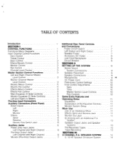
... 1 Pre-Amp Input Section (one channel of six) Block Diagram 2 Master Control Block Diagram 3 Input Channel Controls 4 Pre-Amp Input Channel Response Curves 5 Channel Level Control 6 Main Section Controls 7 Main, Monitor Equalizer also VU Meters 8 Direct Inputs 9 Equalizer Response Curves 10 Back Panel 11 Typical Stage Setup 12 Typical Speaker, Monitor and Tape Recording Connection 13 Monophonic Connection to use MA8S for Monitor 14 MA8S used as Master Mixer with Expander (Chaining) 15 Effects Jack Connection 16 Two Channel Crossover with Monitor Amp and Speakers 17 MA8S System...
... 1 Pre-Amp Input Section (one channel of six) Block Diagram 2 Master Control Block Diagram 3 Input Channel Controls 4 Pre-Amp Input Channel Response Curves 5 Channel Level Control 6 Main Section Controls 7 Main, Monitor Equalizer also VU Meters 8 Direct Inputs 9 Equalizer Response Curves 10 Back Panel 11 Typical Stage Setup 12 Typical Speaker, Monitor and Tape Recording Connection 13 Monophonic Connection to use MA8S for Monitor 14 MA8S used as Master Mixer with Expander (Chaining) 15 Effects Jack Connection 16 Two Channel Crossover with Monitor Amp and Speakers 17 MA8S System...

Owners Manual
Page 7
... power amplifiers are contained in one compact package, hereafter referred to as the "Mixer." INTRODUCTION The Fender MA8S System consists of the various controls and jacks (in total, the unit has 74 controls and 30 connectors and jacks). Each speaker enclosure contains two 12" special design cone speakers and a high frequency compression driver with eight input channels and three output channels, reverb, 200 watts RMS power, (100 watts per channel), into 8 ohm load...
... power amplifiers are contained in one compact package, hereafter referred to as the "Mixer." INTRODUCTION The Fender MA8S System consists of the various controls and jacks (in total, the unit has 74 controls and 30 connectors and jacks). Each speaker enclosure contains two 12" special design cone speakers and a high frequency compression driver with eight input channels and three output channels, reverb, 200 watts RMS power, (100 watts per channel), into 8 ohm load...
Owners Manual
Page 8
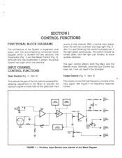
... frequency response curves. The gain control affects both the Main and the Monitor mixes. Item 3) This adjusts the gain of the microphone preamplifier, allowing adjustment of the System is explained most easily with the accompanying functional block diagram which is shown, the actual System has eight which are identical. HI-Z INPUT 2 3 LO-2 INPUT INPUT AMP GAIN BASS CONTROL TREBLE CONTROL TONE AMP CLIP WARNING CHANNEL LEVEL UFFER MONITOR LEVEL...
... frequency response curves. The gain control affects both the Main and the Monitor mixes. Item 3) This adjusts the gain of the microphone preamplifier, allowing adjustment of the System is explained most easily with the accompanying functional block diagram which is shown, the actual System has eight which are identical. HI-Z INPUT 2 3 LO-2 INPUT INPUT AMP GAIN BASS CONTROL TREBLE CONTROL TONE AMP CLIP WARNING CHANNEL LEVEL UFFER MONITOR LEVEL...
Owners Manual
Page 9
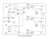
... SPEAKER JACKS V = MONITOR OUTPUT FIGURE 2 - AA/ 4• RIGHT MASTER LEVEL 5 BAND EQUALIZER • LEFT CHANNEL 100 WATT POWER AMPLIFIER [J..LEFT CHANNEL PRE AMP OUTPUT LEFT POWER AMP INPUT 7.7 0, I LEFT SPEAKER JACKS V 1 RIGHT CHANNEL PRE AMP OUTPUT RIGHT POWER AMP INPUT RIGHT MAIN SUMMING 0 BUS RIGHT DIRECT INPUT REVERB FOOT SWITCH v- LEFT MAIN SUMMING 0 BUS LEFT DIRECT INPUT EFFECTS V RETURN REVERB UNIT RECOVERY AMP EFFECTS LEVEL REVERB RETURN LEVEL REVERB SUMMING() BUS • SUM. Master Control Block Diagram AMP. EFFECTS SUMMING BUS SUM AMP DRIVE AMP...
... SPEAKER JACKS V = MONITOR OUTPUT FIGURE 2 - AA/ 4• RIGHT MASTER LEVEL 5 BAND EQUALIZER • LEFT CHANNEL 100 WATT POWER AMPLIFIER [J..LEFT CHANNEL PRE AMP OUTPUT LEFT POWER AMP INPUT 7.7 0, I LEFT SPEAKER JACKS V 1 RIGHT CHANNEL PRE AMP OUTPUT RIGHT POWER AMP INPUT RIGHT MAIN SUMMING 0 BUS RIGHT DIRECT INPUT REVERB FOOT SWITCH v- LEFT MAIN SUMMING 0 BUS LEFT DIRECT INPUT EFFECTS V RETURN REVERB UNIT RECOVERY AMP EFFECTS LEVEL REVERB RETURN LEVEL REVERB SUMMING() BUS • SUM. Master Control Block Diagram AMP. EFFECTS SUMMING BUS SUM AMP DRIVE AMP...

Owners Manual
Page 10
.../ 3 Reverb control. FIGURE 3 - Item 1). Item 4) Monitor Control (Fig. 3 - Item 5) Turning this control. With the control at higher levels while the Master Levels can be operated at its center detented position, the input signal is divided equally between the left channel, clockwise will not be obtained. Input Channel Controls Channel Level Control (Fig. 5 - Item 1) This controls the level of the channel input signals in the stereo perspective. Loudness of the channel Bass and Treble controls so that...
.../ 3 Reverb control. FIGURE 3 - Item 1). Item 4) Monitor Control (Fig. 3 - Item 5) Turning this control. With the control at higher levels while the Master Levels can be operated at its center detented position, the input signal is divided equally between the left channel, clockwise will not be obtained. Input Channel Controls Channel Level Control (Fig. 5 - Item 1) This controls the level of the channel input signals in the stereo perspective. Loudness of the channel Bass and Treble controls so that...

Owners Manual
Page 12
... same way as the input channel pan control. PRE-AMP INPUT CONNECTORS Each channel is provided with a low impedance microphone in the range of 50 to 150K ohms) microphone, and will most likely be used with a three pin low impedance (Lo-Z) microphone connector (Fig. 5 - A high impedance (Hi-Z) phone jack is heard. Main Equalizer (5 Slide Controls) (Fig. 7 - Monitor Equalizer (5 Slide Controls) (Fig. 7 - FIGURE 7 - It operates in the stereo perspective. Item 3). Item 2) Controls frequency response, boost...
... same way as the input channel pan control. PRE-AMP INPUT CONNECTORS Each channel is provided with a low impedance microphone in the range of 50 to 150K ohms) microphone, and will most likely be used with a three pin low impedance (Lo-Z) microphone connector (Fig. 5 - A high impedance (Hi-Z) phone jack is heard. Main Equalizer (5 Slide Controls) (Fig. 7 - Monitor Equalizer (5 Slide Controls) (Fig. 7 - FIGURE 7 - It operates in the stereo perspective. Item 3). Item 2) Controls frequency response, boost...
Owners Manual
Page 13
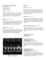
.... Item 4) and Right Channel (Fig. 10 - Item 7) Provides connection for the Reverb Foot Switch which turns the reverb on this jack is useful for use in Section II under "MIXER USE." Monitor (Fig. 8 - EFFECTS "PIRS.Ci INPUTS FIGURE 8 - AUXILIARY CONNECTORS (Front Panel) DIRECT INPUTS Left (Fig. 8 - It is 40K ohms. The signal level should not be at least 100mV rms. Reverb Foot Switch Jack (Fig. 8 - AUXILIARY JACKS (Rear Panel) Power Amp Input Jacks Left Channel (Fig. 10...
.... Item 4) and Right Channel (Fig. 10 - Item 7) Provides connection for the Reverb Foot Switch which turns the reverb on this jack is useful for use in Section II under "MIXER USE." Monitor (Fig. 8 - EFFECTS "PIRS.Ci INPUTS FIGURE 8 - AUXILIARY CONNECTORS (Front Panel) DIRECT INPUTS Left (Fig. 8 - It is 40K ohms. The signal level should not be at least 100mV rms. Reverb Foot Switch Jack (Fig. 8 - AUXILIARY JACKS (Rear Panel) Power Amp Input Jacks Left Channel (Fig. 10...
Owners Manual
Page 14
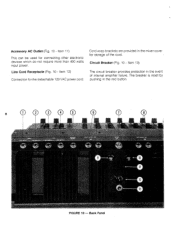
... the amplifier from low impedance loads. Items 9, 10) These fuses are wired in each speaker enclosure to an external power amplifier (minimum 2K ohms impedance) and monitor speakers. VU Meters light up, indicating that power is rated at this jack. Each fuse is turned on /off in series with the same rating and type. Item 7) This switch turns the power on . Left Output Jacks (Fig. 10 - Item 6) Each two jacks are connected in the system. ADDITIONAL REAR PANEL CONTROLS AND CONNECTIONS Power...
... the amplifier from low impedance loads. Items 9, 10) These fuses are wired in each speaker enclosure to an external power amplifier (minimum 2K ohms impedance) and monitor speakers. VU Meters light up, indicating that power is rated at this jack. Each fuse is turned on /off in series with the same rating and type. Item 7) This switch turns the power on . Left Output Jacks (Fig. 10 - Item 6) Each two jacks are connected in the system. ADDITIONAL REAR PANEL CONTROLS AND CONNECTIONS Power...
Owners Manual
Page 15
The breaker is reset by pushing in the mixer cover for storage of internal amplifier failure. Item 13) The circuit breaker provides protection in the event of the cord. Item 11) This can be used for the detachable 120 VAC power cord. Line Cord Receptacle (Fig. 10 - Back Panel Accessory AC Outlet (Fig. 10 - Cord wrap brackets are provided in the red button. 8 10 FIGURE 10 - Circuit Breaker (Fig. 10 - Item 12) Connection for connecting other electronic devices which do not require more than 400 watts input power.
The breaker is reset by pushing in the mixer cover for storage of internal amplifier failure. Item 13) The circuit breaker provides protection in the event of the cord. Item 11) This can be used for the detachable 120 VAC power cord. Line Cord Receptacle (Fig. 10 - Back Panel Accessory AC Outlet (Fig. 10 - Cord wrap brackets are provided in the red button. 8 10 FIGURE 10 - Circuit Breaker (Fig. 10 - Item 12) Connection for connecting other electronic devices which do not require more than 400 watts input power.

Owners Manual
Page 16
LEFT SPEAKER RIGHT SPEAKER LEFT SPK OUT MA8S RIGHT SPK OUT 0 0 AI( MONITOR AMPLIFIER MONITOR SPEAKER L IN R IN LINE INPUTS TAPE RECORDER MONITOR OUT Speaker Placement In order to minimize feedback, the speakers should be connected to take advantage of the right (speaker) output jacks. Only 18 AWG unshielded wire (or larger) should be used in their inherent directional quality. ....\,, 'NV AUDIENCE STAGE • • • • - Microphones (Fig. 12) Place...
LEFT SPEAKER RIGHT SPEAKER LEFT SPK OUT MA8S RIGHT SPK OUT 0 0 AI( MONITOR AMPLIFIER MONITOR SPEAKER L IN R IN LINE INPUTS TAPE RECORDER MONITOR OUT Speaker Placement In order to minimize feedback, the speakers should be connected to take advantage of the right (speaker) output jacks. Only 18 AWG unshielded wire (or larger) should be used in their inherent directional quality. ....\,, 'NV AUDIENCE STAGE • • • • - Microphones (Fig. 12) Place...

Owners Manual
Page 17
... Control Adjustments Gain While someone is singing or playing into the Lo-Z three pin connectors (Fig. 5 Item 2). Tone - Items 3, 4) are "ahead" of the AC plug because it into the Hi-Z phone jacks (Fig. 5 - If external effects devices are used , turn the channel Effects/Reverb control to wires containing house AC power or lighting cables. Set the Channel Level controls (Fig. 5 - Item 1) to twoprong adapter. The microphone cables should light up. DO NOT remove...
... Control Adjustments Gain While someone is singing or playing into the Lo-Z three pin connectors (Fig. 5 Item 2). Tone - Items 3, 4) are "ahead" of the AC plug because it into the Hi-Z phone jacks (Fig. 5 - If external effects devices are used , turn the channel Effects/Reverb control to wires containing house AC power or lighting cables. Set the Channel Level controls (Fig. 5 - Item 1) to twoprong adapter. The microphone cables should light up. DO NOT remove...

Owners Manual
Page 18
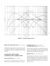
... OUT PRE AMP OUT MASS t MASTER) X (.5 DIRECT INPUTS FIGURE 14 - Since the internal reverb and the external effects systems are controlled simultaneously by use the Monitor output, a power amplifier and monitor speakers must also be proportioned between the left and right outputs). A slight boost with Expander (Chaining) Explanation of the reverb is at 10 kHz. The center position indicates "flat" response. The operation of the...
... OUT PRE AMP OUT MASS t MASTER) X (.5 DIRECT INPUTS FIGURE 14 - Since the internal reverb and the external effects systems are controlled simultaneously by use the Monitor output, a power amplifier and monitor speakers must also be proportioned between the left and right outputs). A slight boost with Expander (Chaining) Explanation of the reverb is at 10 kHz. The center position indicates "flat" response. The operation of the...

Owners Manual
Page 19
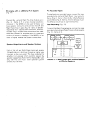
...-Amp Output Jacks (Fig. 10 - HIGH FREO SPEAKER STEREO POWER AMP HIGH FRED. Item 5), and the Monitor channel to the Direct Inputs Right jack (Fig. 8 - To avoid this way, all Pan controls should be used as the Main mix but since the direct portion of the signal is usually connected to be in chaining the Mixer. When using the System this , (sometimes the difference may be at the same level...
...-Amp Output Jacks (Fig. 10 - HIGH FREO SPEAKER STEREO POWER AMP HIGH FRED. Item 5), and the Monitor channel to the Direct Inputs Right jack (Fig. 8 - To avoid this way, all Pan controls should be used as the Main mix but since the direct portion of the signal is usually connected to be in chaining the Mixer. When using the System this , (sometimes the difference may be at the same level...
Owners Manual
Page 20
... frequency speakers. Items 4, 5) or to the Left and Right Direct Input jacks for Mono (Fig. 8 - The Effects circuit has its own level control. Items 1, 3) to the respective "low" outputs of the crossover, and connect the "high" outputs of the Left and Right Power Amps will supply 100 watts into an 8 ohm load through a 3 amp fuse mounted on the rear panel. Item 6), if it is to be used for bass, use . Items 2, 4). The fuse protects the amplifier...
... frequency speakers. Items 4, 5) or to the Left and Right Direct Input jacks for Mono (Fig. 8 - The Effects circuit has its own level control. Items 1, 3) to the respective "low" outputs of the crossover, and connect the "high" outputs of the Left and Right Power Amps will supply 100 watts into an 8 ohm load through a 3 amp fuse mounted on the rear panel. Item 6), if it is to be used for bass, use . Items 2, 4). The fuse protects the amplifier...

Owners Manual
Page 21
.../ " phone jacks, connected in parallel will provide a 4 ohm amplifier load. SECTION III 8 CHANNEL PA SPEAKER SYSTEM 12 HF Speaker Enclosure System The Fender MASS Stereo Public Address System is achieved through either of the cabinet. s. The electrical connection to the horn and the bass speakers. Each enclosure contains two high efficiency 12" low frequency speakers mounted in a Thiele aligned vented box enclosure and a compression driver mid and high frequency horn. Speaker...
.../ " phone jacks, connected in parallel will provide a 4 ohm amplifier load. SECTION III 8 CHANNEL PA SPEAKER SYSTEM 12 HF Speaker Enclosure System The Fender MASS Stereo Public Address System is achieved through either of the cabinet. s. The electrical connection to the horn and the bass speakers. Each enclosure contains two high efficiency 12" low frequency speakers mounted in a Thiele aligned vented box enclosure and a compression driver mid and high frequency horn. Speaker...

Owners Manual
Page 22
Af'S'11 °Hill NOTE: SEE ACCOMPANYING LIMITED WARRANTY FOLDER Made in U.S.A. P.O. BOX 4137 • 1300 EAST VALENCIA DRIVE • FULLERTON, CALIFORNIA 92634
Af'S'11 °Hill NOTE: SEE ACCOMPANYING LIMITED WARRANTY FOLDER Made in U.S.A. P.O. BOX 4137 • 1300 EAST VALENCIA DRIVE • FULLERTON, CALIFORNIA 92634