Product Manual
Page 2
... nearest Fluke authorized service center to obtain return authorization information, then send the product to that Service Center with a description of purchase. FLUKE IS NOT LIABLE FOR ANY SPECIAL, INDIRECT, INCIDENTAL OR CONSEQUENTIAL DAMAGES OR LOSSES, ARISING FROM ANY CAUSE OR THEORY. P.O. This warranty does not cover fuses, disposable batteries, or damage from the date of the problem.
... nearest Fluke authorized service center to obtain return authorization information, then send the product to that Service Center with a description of purchase. FLUKE IS NOT LIABLE FOR ANY SPECIAL, INDIRECT, INCIDENTAL OR CONSEQUENTIAL DAMAGES OR LOSSES, ARISING FROM ANY CAUSE OR THEORY. P.O. This warranty does not cover fuses, disposable batteries, or damage from the date of the problem.

Product Manual
Page 3
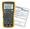
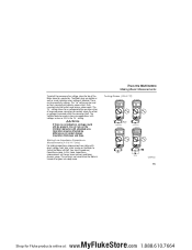
... Model 117 are in the correct terminals, LEAd is briefly displayed and an audible beep sounds when you move the rotary switch to protect against transients in an incorrect terminal. The IEC 61010-1 2nd Edition safety standard defines four measurement categories (CAT I to the presence of danger from any A (Amps) position. 1 MyFlukeStore Shop for Fluke products online...
... Model 117 are in the correct terminals, LEAd is briefly displayed and an audible beep sounds when you move the rotary switch to protect against transients in an incorrect terminal. The IEC 61010-1 2nd Edition safety standard defines four measurement categories (CAT I to the presence of danger from any A (Amps) position. 1 MyFlukeStore Shop for Fluke products online...
Product Manual
Page 4
... Fluke products online at: www. .com 1.888.610.7664 To avoid possible electric shock or personal injury, follow these guidelines: • Use the Meter only as marked on Meter, between terminals or between any terminal and earth ground. • Use caution with voltages above 30 V ac rms, 42 V ac peak, or 60 V dc. 114, 115, and 117 Users Manual...
... Fluke products online at: www. .com 1.888.610.7664 To avoid possible electric shock or personal injury, follow these guidelines: • Use the Meter only as marked on Meter, between terminals or between any terminal and earth ground. • Use caution with voltages above 30 V ac rms, 42 V ac peak, or 60 V dc. 114, 115, and 117 Users Manual...
Product Manual
Page 5
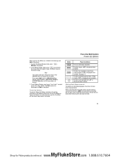
... replacement fuse specified or the protection may be damaged by this product as required by local or national authorities when working in hazardous areas. • Avoid working in hazardous locations. • Use proper protective equipment, as unsorted ~ municipal waste. Symbols B AC (Alternating Current) F DC (Direct Current) X Hazardous voltage N Battery (Low battery when shown on the display.) I Fuse T Double Insulated W Important Information...
... replacement fuse specified or the protection may be damaged by this product as required by local or national authorities when working in hazardous areas. • Avoid working in hazardous locations. • Use proper protective equipment, as unsorted ~ municipal waste. Symbols B AC (Alternating Current) F DC (Direct Current) X Hazardous voltage N Battery (Low battery when shown on the display.) I Fuse T Double Insulated W Important Information...
Product Manual
Page 6
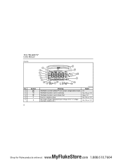
A B C D E 4 Symbol w s R O Y 6 5 4 3 2 1 16 15 VoltAlert 7 14 17 8 9 10 11 12 13 18 Meaning The Meter is a negative value. X Unsafe voltage. The Meter function is set to Diode Test Input is in the VoltAlert™ non-contact voltage detect mode. 114, 115, and 117 Users Manual Display No. Measured input voltage ≥30 V, or voltage overload condition (OL). The Meter function is set to Continuity. edy02f.eps Model 117 114, 115, & 117 115 & 117 114, 115, & 117 114, 115, & 117 MyFlukeStore Shop for Fluke products online at: www. .com 1.888.610.7664
A B C D E 4 Symbol w s R O Y 6 5 4 3 2 1 16 15 VoltAlert 7 14 17 8 9 10 11 12 13 18 Meaning The Meter is a negative value. X Unsafe voltage. The Meter function is set to Diode Test Input is in the VoltAlert™ non-contact voltage detect mode. 114, 115, and 117 Users Manual Display No. Measured input voltage ≥30 V, or voltage overload condition (OL). The Meter function is set to Continuity. edy02f.eps Model 117 114, 115, & 117 115 & 117 114, 115, & 117 114, 115, & 117 MyFlukeStore Shop for Fluke products online at: www. .com 1.888.610.7664
Product Manual
Page 7
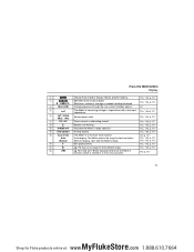
... for the selected range. 114, 115, & 117 R LEAd W Test lead alert. User sets the Meter's range. 114, 115, & 117 P + Bar graph polarity 114, 115, & 117 Q 0L W The input is rotated to or from any A position. 115 & 117 5 MyFlukeStore Shop for best resolution. 114, 115, & 117 Manual Manual ranging. Display freezes present reading. 114, 115, & 117 G M MIN MAX AVG mode enabled. The Meter selects the range for Fluke products online at: www...
... for the selected range. 114, 115, & 117 R LEAd W Test lead alert. User sets the Meter's range. 114, 115, & 117 P + Bar graph polarity 114, 115, & 117 Q 0L W The input is rotated to or from any A position. 115 & 117 5 MyFlukeStore Shop for best resolution. 114, 115, & 117 Manual Manual ranging. Display freezes present reading. 114, 115, & 117 G M MIN MAX AVG mode enabled. The Meter selects the range for Fluke products online at: www...
Product Manual
Page 8
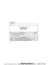
..., & 117 bAtt CAL Err EEPr Err F11 Err Error Messages Battery must be repaired before the Meter will operate. Internal error. Meter calibration is required before it will operate. Description A Input terminal for measuring voltage, continuity, resistance, capacitance, frequency and testing diodes. B Common (return) terminal for Fluke products online at: www. .com 1.888.610.7664 Internal error. Calibration required. 114, 115, and 117 Users Manual Terminals 1 V A COM 3 10 A FUSED...
..., & 117 bAtt CAL Err EEPr Err F11 Err Error Messages Battery must be repaired before the Meter will operate. Internal error. Meter calibration is required before it will operate. Description A Input terminal for measuring voltage, continuity, resistance, capacitance, frequency and testing diodes. B Common (return) terminal for Fluke products online at: www. .com 1.888.610.7664 Internal error. Calibration required. 114, 115, and 117 Users Manual Terminals 1 V A COM 3 10 A FUSED...
Product Manual
Page 9
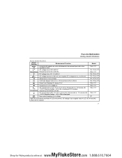
... Switch Positions Switch Position Measurement Function Model x e Hz (button) D l Automatically selects ac or dc volts based on , 10 minutes off). >10.00 A display flashes. >20 A, OL is displayed. Frequency from 45 Hz to 20 A, 30 seconds on at < 20 Ω and turns off ). >10.00 A display flashes. >20 A, OL is ac-coupled. S Farads from 1 nF to 9999 μF. 115 & 117 115 & 117 j Hz (button...
... Switch Positions Switch Position Measurement Function Model x e Hz (button) D l Automatically selects ac or dc volts based on , 10 minutes off). >10.00 A display flashes. >20 A, OL is displayed. Frequency from 45 Hz to 20 A, 30 seconds on at < 20 Ω and turns off ). >10.00 A display flashes. >20 A, OL is ac-coupled. S Farads from 1 nF to 9999 μF. 115 & 117 115 & 117 j Hz (button...
Product Manual
Page 10
... (AVG), and present readings. • To pause MIN MAX AVG recording without erasing stored values, press f. 114, 115, and 117 Users Manual Battery Saver ("Sleep Mode") The Meter automatically enters "Sleep mode" and blanks the display if there is no function change, range change, or button press for Fluke products online at least one second or turn the rotary switch. To disable backlight auto-off after 40 seconds.
... (AVG), and present readings. • To pause MIN MAX AVG recording without erasing stored values, press f. 114, 115, and 117 Users Manual Battery Saver ("Sleep Mode") The Meter automatically enters "Sleep mode" and blanks the display if there is no function change, range change, or button press for Fluke products online at least one second or turn the rotary switch. To disable backlight auto-off after 40 seconds.
Product Manual
Page 11
... invalid operation and the range does not change the range in the MIN MAX AVG or Display HOLD modes. In the Manual Range mode, press qto increment the range. Manual is displayed when enabled. Note You cannot manually change . 3. The Meter returns to Autorange and Auto is activated. Power-Up Options are canceled when you turn the Meter on, it defaults to Autorange and Auto is displayed when enabled. When you turn the Meter...
... invalid operation and the range does not change the range in the MIN MAX AVG or Display HOLD modes. In the Manual Range mode, press qto increment the range. Manual is displayed when enabled. Note You cannot manually change . 3. The Meter returns to Autorange and Auto is activated. Power-Up Options are canceled when you turn the Meter on, it defaults to Autorange and Auto is displayed when enabled. When you turn the Meter...

Product Manual
Page 13
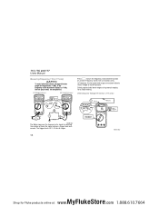
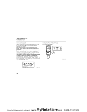
... Shop for Fluke products online at: www. .com 1.888.610.7664 edy18f.eps With the function switch in the x position, the Meter automatically selects a dc or ac voltage measurement based on the input applied between the V or + and COM jacks. Measuring AC and DC Millivolts Millivolts AC Millivolts DC DC edy03f.eps Using Auto Volts Selection (114 & 117 only...
... Shop for Fluke products online at: www. .com 1.888.610.7664 edy18f.eps With the function switch in the x position, the Meter automatically selects a dc or ac voltage measurement based on the input applied between the V or + and COM jacks. Measuring AC and DC Millivolts Millivolts AC Millivolts DC DC edy03f.eps Using Auto Volts Selection (114 & 117 only...
Product Manual
Page 14
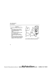
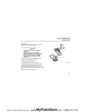
... Fuse") • Use the proper terminals, switch position, and range for your measurement. • Never place the probes in parallel with a circuit or component when the leads are plugged into the A (Amps) terminals. 1 A 2 3 edy08f.eps Turn circuit power off, break the circuit, insert the Meter in series with the circuit, and then turn circuit power on. 12 MyFlukeStore Shop for Fluke...
... Fuse") • Use the proper terminals, switch position, and range for your measurement. • Never place the probes in parallel with a circuit or component when the leads are plugged into the A (Amps) terminals. 1 A 2 3 edy08f.eps Turn circuit power off, break the circuit, insert the Meter in series with the circuit, and then turn circuit power on. 12 MyFlukeStore Shop for Fluke...
Product Manual
Page 16
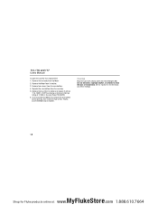
... frequency of a signal by counting the number of the measured signal is 0 V, 0 A for all ranges. 14 VoltAlert edy13f.eps MyFlukeStore Shop for frequencies >1 kHz. 114, 115, and 117 Users Manual Measuring Frequency (115 & 117 only) XWWarning To avoid electrical shock, disregard the bar graph for Fluke products online at: www. .com 1.888.610.7664 AC Voltage Frequency AC Current Frequency VoltAlert Hz Press g to turn the frequency...
... frequency of a signal by counting the number of the measured signal is 0 V, 0 A for all ranges. 14 VoltAlert edy13f.eps MyFlukeStore Shop for frequencies >1 kHz. 114, 115, and 117 Users Manual Measuring Frequency (115 & 117 only) XWWarning To avoid electrical shock, disregard the bar graph for Fluke products online at: www. .com 1.888.610.7664 AC Voltage Frequency AC Current Frequency VoltAlert Hz Press g to turn the frequency...
Product Manual
Page 17
... indication, voltage could still be used on the VoltAlert detector with voltages as low as visual indication when voltage is detected. Operation may be effected by differences in bare wire applications with shielded wire. This setting is not saved when the Meter is recessed within the connector itself. The "Hi" setting allows for Fluke products online at: www. .com 1.888...
... indication, voltage could still be used on the VoltAlert detector with voltages as low as visual indication when voltage is detected. Operation may be effected by differences in bare wire applications with shielded wire. This setting is not saved when the Meter is recessed within the connector itself. The "Hi" setting allows for Fluke products online at: www. .com 1.888...
Product Manual
Page 18
The number of −30 V turns on the negative sign and the segments up to the left. In the 60 V range, for making peak and null adjustments. An input of segments indicates the measured value and is useful for example (see ...digital display, the bar graph is relative to the middle of the selected range. In frequency, the bar graph and range annunciator indicates the underlying voltage or current up to the full-scale value of the scale. Testing the Fuse (115 & 117 only) Test fuse as shown below ), the major divisions on an analog meter. 114, 115, and 117 Users Manual Using...
The number of −30 V turns on the negative sign and the segments up to the left. In the 60 V range, for making peak and null adjustments. An input of segments indicates the measured value and is useful for example (see ...digital display, the bar graph is relative to the middle of the selected range. In frequency, the bar graph and range annunciator indicates the underlying voltage or current up to the full-scale value of the scale. Testing the Fuse (115 & 117 only) Test fuse as shown below ), the major divisions on an analog meter. 114, 115, and 117 Users Manual Using...
Product Manual
Page 19
... from the Meter before opening the case or battery door. • Use ONLY a fuse with the amperage, interrupt voltage, and speed ratings specified. True-rms Multimeters Maintenance Fuse edy11f.eps 17 MyFlukeStore Shop for battery replacement: 1. Do not attempt to separate it is then inserted into the case. 5. Lift the door straight up to install the battery directly into the...
... from the Meter before opening the case or battery door. • Use ONLY a fuse with the amperage, interrupt voltage, and speed ratings specified. True-rms Multimeters Maintenance Fuse edy11f.eps 17 MyFlukeStore Shop for battery replacement: 1. Do not attempt to separate it is then inserted into the case. 5. Lift the door straight up to install the battery directly into the...
Product Manual
Page 20
... 117 Users Manual To open the case for Fluke products online at: www. .com 1.888.610.7664 Do not use abrasives, isopropyl alcohol, or solvents to the case top, then install the two screws. Use only Fluke PN 803293. 6. Cleaning Wipe the case with an 11 A, 1000 V, FAST fuse having a minimum interrupt rating of 17,000 A. To re-assemble the Meter...
... 117 Users Manual To open the case for Fluke products online at: www. .com 1.888.610.7664 Do not use abrasives, isopropyl alcohol, or solvents to the case top, then install the two screws. Use only Fluke PN 803293. 6. Cleaning Wipe the case with an 11 A, 1000 V, FAST fuse having a minimum interrupt rating of 17,000 A. To re-assemble the Meter...
Product Manual
Page 21
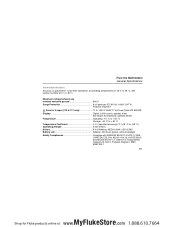
...Multimeters General Specifications General Specifications Accuracy is specified for 1 year after calibration, at operating temperatures ... 19 MyFlukeStore Shop for A input (115 & 117 only 11 A, 1000 V FAST 17 kA Fuse (Fluke PN 803293) Display Digital: 6,000 counts, updates 4/sec Bar Graph: 33 segments, updates 32/sec Temperature Operating: -10 °C to +... 2 W Fuse for Fluke products online at 0 % to + 60 °C Temperature Coefficient 0.1 x (specified accuracy)/°C (28 °C) Operating Altitude 2,000 meters Battery 9 Volt Alkaline, NEDA 1604A / IEC 6LR61 Battery Life Alkaline...
...Multimeters General Specifications General Specifications Accuracy is specified for 1 year after calibration, at operating temperatures ... 19 MyFlukeStore Shop for A input (115 & 117 only 11 A, 1000 V FAST 17 kA Fuse (Fluke PN 803293) Display Digital: 6,000 counts, updates 4/sec Bar Graph: 33 segments, updates 32/sec Temperature Operating: -10 °C to +... 2 W Fuse for Fluke products online at 0 % to + 60 °C Temperature Coefficient 0.1 x (specified accuracy)/°C (28 °C) Operating Altitude 2,000 meters Battery 9 Volt Alkaline, NEDA 1604A / IEC 6LR61 Battery Life Alkaline...
Product Manual
Page 22
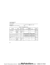
...and 117 Users Manual Certifications UL, P, CSA, TÜV, ; (N10140), VDE IP Rating (dust and water protection IP42 Table 1. Accuracy Specifications Function Range Resolution Accuracy ± ([% of Reading] + [Counts]) DC millivolts DC Volts 600.0 mV 6.000 V 60.00 V 600.0 V Auto-V LoZ... V 0.5 % + 2 0.5 % + 2 DC, 45 to 500 Hz 2.0 % + 3 45 to 500 Hz 1.0 % + 3 500 Hz to 1 kHz 4.0 % + 3 500 Hz to 1 kHz 2.0 % + 3 1.0 % + 3 2.0 % + 3 Model 114, 115, 117 114, 115, 117 114, 117 114, 115, 117 114, 115, 117 20 MyFlukeStore Shop for Fluke products online at: www. .com 1.888.610.7664
...and 117 Users Manual Certifications UL, P, CSA, TÜV, ; (N10140), VDE IP Rating (dust and water protection IP42 Table 1. Accuracy Specifications Function Range Resolution Accuracy ± ([% of Reading] + [Counts]) DC millivolts DC Volts 600.0 mV 6.000 V 60.00 V 600.0 V Auto-V LoZ... V 0.5 % + 2 0.5 % + 2 DC, 45 to 500 Hz 2.0 % + 3 45 to 500 Hz 1.0 % + 3 500 Hz to 1 kHz 4.0 % + 3 500 Hz to 1 kHz 2.0 % + 3 1.0 % + 3 2.0 % + 3 Model 114, 115, 117 114, 115, 117 114, 117 114, 115, 117 114, 115, 117 20 MyFlukeStore Shop for Fluke products online at: www. .com 1.888.610.7664
Product Manual
Page 24
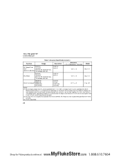
... decreasing linearly to 1.5 at : www. .com 1.888.610.7664 114, 115, and 117 Users Manual Table 1 Accuracy Specifications (cont.) Function Range Resolution Accuracy ± ([% of Reading] + [Counts]) Model AC Amps Truerms[1] (45 Hz to 500 Hz) 6.000 A 10.00 A[3] 20 ...117 Notes: [1] All ac ranges except Auto-V LoZ are shorted together. Auto-V LoZ is ac-coupled and specified from 45 Hz to 5 kHz. [3] >10 A unspecified. 22 MyFlukeStore Shop for Fluke products online at full scale. Because inputs below 1 % of range are dc-coupled. [2] AC Volts Hz is specified from 1 % to display...
... decreasing linearly to 1.5 at : www. .com 1.888.610.7664 114, 115, and 117 Users Manual Table 1 Accuracy Specifications (cont.) Function Range Resolution Accuracy ± ([% of Reading] + [Counts]) Model AC Amps Truerms[1] (45 Hz to 500 Hz) 6.000 A 10.00 A[3] 20 ...117 Notes: [1] All ac ranges except Auto-V LoZ are shorted together. Auto-V LoZ is ac-coupled and specified from 45 Hz to 5 kHz. [3] >10 A unspecified. 22 MyFlukeStore Shop for Fluke products online at full scale. Because inputs below 1 % of range are dc-coupled. [2] AC Volts Hz is specified from 1 % to display...


