Fluke 1520 MegOhmMeter Datasheet
Page 1
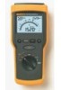
Fluke 1520 MegOhmMeter Technical Data The Fluke 1520 MegOhmMeter is greater than 30V ac or 30V dc. • AC/DC voltage measurement up to 600V • Lo-Ohms function for testing connections • ...
Fluke 1520 MegOhmMeter Technical Data The Fluke 1520 MegOhmMeter is greater than 30V ac or 30V dc. • AC/DC voltage measurement up to 600V • Lo-Ohms function for testing connections • ...
Fluke 1520 MegOhmMeter Datasheet
Page 2
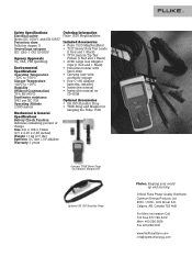
...108 x 72mm (9.5 x 4.25 x 2.85 inches) Weight 1.1 kg (2.5 lbs) Batteries 4 C size 1.5V alkaline Warranty 3 years Ordering Information Fluke 1520 MegOhmMeter Included Accessories • Fluke 1520 MegOhmMeter • TL27 Heavy Duty Test Leads (1 Red and 1 Black) • TP74 Lantern Tip Test Probes (1 Red and 1 Black) •...8226; SH 100 Shoulder Strap • TPAK Strap and Magnet for hanging the Fluke 1520 Optional TPAK Meter Strap and Magnet Hanging Kit Optional SH 100 Shoulder Strap Fluke. Safety Specifications Electrical safety Meets IEC 1010-1 and EN 61557 Protection class Pollution...
...108 x 72mm (9.5 x 4.25 x 2.85 inches) Weight 1.1 kg (2.5 lbs) Batteries 4 C size 1.5V alkaline Warranty 3 years Ordering Information Fluke 1520 MegOhmMeter Included Accessories • Fluke 1520 MegOhmMeter • TL27 Heavy Duty Test Leads (1 Red and 1 Black) • TP74 Lantern Tip Test Probes (1 Red and 1 Black) •...8226; SH 100 Shoulder Strap • TPAK Strap and Magnet for hanging the Fluke 1520 Optional TPAK Meter Strap and Magnet Hanging Kit Optional SH 100 Shoulder Strap Fluke. Safety Specifications Electrical safety Meets IEC 1010-1 and EN 61557 Protection class Pollution...
FE 1520 Users Manual
Page 6
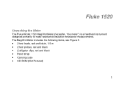
Fluke 1520 Unpacking the Meter The Fluke Model 1520 MegOhmMeter (hereafter, "the meter") is a handheld instrument designed primarily to make resistance/insulation resistance measurements. The MegOhmMeter includes the following items, see Figure 1: • 2 test leads, red and black, 1.5 m • 2 test probes, red and black • 2 alligator clips, red and black • Hand strap • Carrying case • CD ROM (Not Pictured) 1
Fluke 1520 Unpacking the Meter The Fluke Model 1520 MegOhmMeter (hereafter, "the meter") is a handheld instrument designed primarily to make resistance/insulation resistance measurements. The MegOhmMeter includes the following items, see Figure 1: • 2 test leads, red and black, 1.5 m • 2 test probes, red and black • 2 alligator clips, red and black • Hand strap • Carrying case • CD ROM (Not Pictured) 1
FE 1520 Users Manual
Page 9
... not use the Meter if it looks damaged. • Be careful when working alone. • Inspect the test leads for damaged insulation or exposed metal. Fluke 1520 Users Manual W Safety Information Use of additional operating circuits connected in a manner not specified by the manufacturer may impair safety features/protection provided by transient...
... not use the Meter if it looks damaged. • Be careful when working alone. • Inspect the test leads for damaged insulation or exposed metal. Fluke 1520 Users Manual W Safety Information Use of additional operating circuits connected in a manner not specified by the manufacturer may impair safety features/protection provided by transient...
FE 1520 Users Manual
Page 11
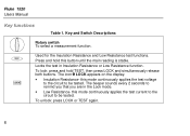
... in the Lock mode. • Low Resistance- The beeper sounds every 2 seconds to be tested. The icon V LOCK appears on the display. • Insulation Resistance- Fluke 1520 Users Manual Key functions Table 1. To unlock: press LOCK or TEST again. 6 Key and Switch Descriptions T L Rotary switch To select a measurement function.
... in the Lock mode. • Low Resistance- The beeper sounds every 2 seconds to be tested. The icon V LOCK appears on the display. • Insulation Resistance- Fluke 1520 Users Manual Key functions Table 1. To unlock: press LOCK or TEST again. 6 Key and Switch Descriptions T L Rotary switch To select a measurement function.
FE 1520 Users Manual
Page 13
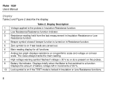
Display Description 1 Voltage applied to a function. Displays briefly when the Meter is locked in Resistance function. 5 Zero symbol is present on a linear scale. Fluke 1520 Users Manual Display Table 2 and Figure 2 describe the display. The value always tracks the main reading. 8 High voltage warning symbol flashes if voltage ≥ 30 V ...
Display Description 1 Voltage applied to a function. Displays briefly when the Meter is locked in Resistance function. 5 Zero symbol is present on a linear scale. Fluke 1520 Users Manual Display Table 2 and Figure 2 describe the display. The value always tracks the main reading. 8 High voltage warning symbol flashes if voltage ≥ 30 V ...
FE 1520 Users Manual
Page 15
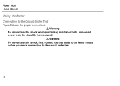
Warning To prevent electric shock when performing resistance tests, remove all W power from the circuit to the circuit under test. 10 Warning To prevent electric shock, first connect the test leads to the Meter inputs before you make connection to be measured. Fluke 1520 Users Manual Using the Meter Connecting to the Circuit Under Test W Figure 3 shows the proper connections.
Warning To prevent electric shock when performing resistance tests, remove all W power from the circuit to the circuit under test. 10 Warning To prevent electric shock, first connect the test leads to the Meter inputs before you make connection to be measured. Fluke 1520 Users Manual Using the Meter Connecting to the Circuit Under Test W Figure 3 shows the proper connections.
FE 1520 Users Manual
Page 17
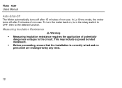
W Measuring Insulation Resistance Warning • Measuring insulation resistance requires the application of potentially dangerous voltages to the desired function. Fluke 1520 Users Manual Auto-Shut-Off The Meter automatically turns off after 15 minutes of non-use . In Lo Ohms mode, the meter turns off after 5 minutes of non-use . This may include exposed bonded metalwork. • Before proceeding, ensure that the installation is correctly wired and no personnel are endangered by any tests. 12 To turn the meter back on, turn the rotary switch to OFF, then to the circuit.
W Measuring Insulation Resistance Warning • Measuring insulation resistance requires the application of potentially dangerous voltages to the desired function. Fluke 1520 Users Manual Auto-Shut-Off The Meter automatically turns off after 15 minutes of non-use . In Lo Ohms mode, the meter turns off after 5 minutes of non-use . This may include exposed bonded metalwork. • Before proceeding, ensure that the installation is correctly wired and no personnel are endangered by any tests. 12 To turn the meter back on, turn the rotary switch to OFF, then to the circuit.
FE 1520 Users Manual
Page 19
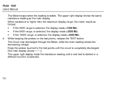
... selected, the display reads >1000 MΩ. • If the 500V range, is selected, the display reads >2000 MΩ. • If the 1000V range, is stable. Fluke 1520 Users Manual The Meter beeps when the reading is selected, the display reads >4000 MΩ. 4.
... selected, the display reads >1000 MΩ. • If the 500V range, is selected, the display reads >2000 MΩ. • If the 1000V range, is stable. Fluke 1520 Users Manual The Meter beeps when the reading is selected, the display reads >4000 MΩ. 4.
FE 1520 Users Manual
Page 21
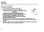
... test lead resistance (see Table 1). 2. acf06f.eps 3. The upper right display holds the resistance reading until a new test is started or a different function is displayed. 4. Fluke 1520 Users Manual Measuring Low Resistance To measure low resistance: 1. Connect the probes to the circuit to be measured. A single beep indicates a stable reading.
... test lead resistance (see Table 1). 2. acf06f.eps 3. The upper right display holds the resistance reading until a new test is started or a different function is displayed. 4. Fluke 1520 Users Manual Measuring Low Resistance To measure low resistance: 1. Connect the probes to the circuit to be measured. A single beep indicates a stable reading.
FE 1520 Users Manual
Page 23
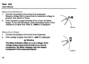
... the resistance is higher than 660 V, >660 V is approximately 30 Ω or less, the Meter beeps. Connect the probes to the circuit to be measured. Fluke 1520 Users Manual Measuring Resistance 1. To turn off the beeper, press the beeper button. Measuring Voltage 1. Connect the probes to the circuit to be measured. Measure...
... the resistance is higher than 660 V, >660 V is approximately 30 Ω or less, the Meter beeps. Connect the probes to the circuit to be measured. Fluke 1520 Users Manual Measuring Resistance 1. To turn off the beeper, press the beeper button. Measuring Voltage 1. Connect the probes to the circuit to be measured. Measure...
FE 1520 Users Manual
Page 25
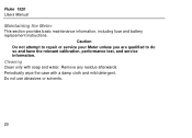
Periodically wipe the case with soap and water. Caution Do not attempt to repair or service your Meter unless you are qualified to do so and have the relevant calibration, performance test, and service information. Cleaning Clean only with a damp cloth and mild detergent. Remove any residue afterwards. Fluke 1520 Users Manual Maintaining the Meter This section provides basic maintenance information, including fuse and battery replacement instructions. Do not use abrasives or solvents. 20
Periodically wipe the case with soap and water. Caution Do not attempt to repair or service your Meter unless you are qualified to do so and have the relevant calibration, performance test, and service information. Cleaning Clean only with a damp cloth and mild detergent. Remove any residue afterwards. Fluke 1520 Users Manual Maintaining the Meter This section provides basic maintenance information, including fuse and battery replacement instructions. Do not use abrasives or solvents. 20
FE 1520 Users Manual
Page 27
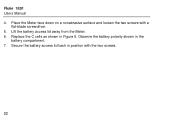
Fluke 1520 Users Manual 4. Lift the battery access lid away from the Meter. 6. Replace the C cells as shown in the battery compartment. 7. Secure the battery access lid back in position with a flat-blade screwdriver. 5. Place the Meter face down on a nonabrasive surface and loosen the two screws with the two screws. 22 Observe the battery polarity shown in Figure 5.
Fluke 1520 Users Manual 4. Lift the battery access lid away from the Meter. 6. Replace the C cells as shown in the battery compartment. 7. Secure the battery access lid back in position with a flat-blade screwdriver. 5. Place the Meter face down on a nonabrasive surface and loosen the two screws with the two screws. 22 Observe the battery polarity shown in Figure 5.
FE 1520 Users Manual
Page 29
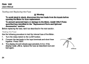
... the rotary switch to test the internal fuse of the Meter. 1. Connect the test leads to the Meter, install ONLY Fluke specified fuse identified in the next section. acf06f.eps 24 Fluke 1520 Users Manual W Testing and Replacing the Fuse Warning To avoid electric shock, disconnect the test leads from the inputs before...
... the rotary switch to test the internal fuse of the Meter. 1. Connect the test leads to the Meter, install ONLY Fluke specified fuse identified in the next section. acf06f.eps 24 Fluke 1520 Users Manual W Testing and Replacing the Fuse Warning To avoid electric shock, disconnect the test leads from the inputs before...
FE 1520 Users Manual
Page 31
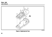
Fluke 1520 Users Manual Figure 6. Replacing the Fuse acf11f.eps 26
Fluke 1520 Users Manual Figure 6. Replacing the Fuse acf11f.eps 26
FE 1520 Users Manual
Page 33
Fluke 1520 Users Manual Principle of Measurement for Resistance The Meter measures resistance by performing the following calculation: R = V (Ohm's Law) I Service Centers To locate an authorized service center, visit us on the World Wide Web: www.fluke.com or call Fluke using any of the circuit. The resistance is ... the resultant potential across the circuit, and then calculating the resistance of the phone numbers listed below: USA: 1-888-99-FLUKE (1-888-993-5853) Canada: 1-800-36-FLUKE (1-800-363-5853) Europe: +31 402-678-200 Japan: +81-3-3434-0181 Singapore: +65-738-5655 Anywhere in the...
Fluke 1520 Users Manual Principle of Measurement for Resistance The Meter measures resistance by performing the following calculation: R = V (Ohm's Law) I Service Centers To locate an authorized service center, visit us on the World Wide Web: www.fluke.com or call Fluke using any of the circuit. The resistance is ... the resultant potential across the circuit, and then calculating the resistance of the phone numbers listed below: USA: 1-888-99-FLUKE (1-888-993-5853) Canada: 1-800-36-FLUKE (1-800-363-5853) Europe: +31 402-678-200 Japan: +81-3-3434-0181 Singapore: +65-738-5655 Anywhere in the...
FE 1520 Users Manual
Page 35
Fluke 1520 Users Manual Size Weight Drop requirement Shock and Vibration Electrical Safety Maximum Operating Voltage Protection Levels Immunity & Emmissions ESD Mechanical Specifications 23,4 x 10 x 6,4 cm (9.2 x 3.9 x 2.5 in) 1 ...
Fluke 1520 Users Manual Size Weight Drop requirement Shock and Vibration Electrical Safety Maximum Operating Voltage Protection Levels Immunity & Emmissions ESD Mechanical Specifications 23,4 x 10 x 6,4 cm (9.2 x 3.9 x 2.5 in) 1 ...
FE 1520 Users Manual
Page 37
Fluke 1520 Users Manual Test Voltages Accuracy Nominal Current Number of measurements Circuitry Protection Display Range Measurement Range Accuracy Resolution Analog Bar Graph Open Circuit Voltage Short ...
Fluke 1520 Users Manual Test Voltages Accuracy Nominal Current Number of measurements Circuitry Protection Display Range Measurement Range Accuracy Resolution Analog Bar Graph Open Circuit Voltage Short ...
FE 1520 Users Manual
Page 39
... abnormal condition of operation or handling, including overvoltage failures caused by accident or abnormal conditions of operation or handling. Fluke 1520 Users Manual Limited Warranty & Limitation of Liability Each Fluke product is warranted to be free from defects in transit. Fluke assumes no authority to extend a greater or different warranty on the date of...
... abnormal condition of operation or handling, including overvoltage failures caused by accident or abnormal conditions of operation or handling. Fluke 1520 Users Manual Limited Warranty & Limitation of Liability Each Fluke product is warranted to be free from defects in transit. Fluke assumes no authority to extend a greater or different warranty on the date of...

FE 1520 Users Manual
Page 41
Fluke 1520 Users Manual 36
Fluke 1520 Users Manual 36


