
FE PowerLog Users Manual
Page 2
...interruption, loss of business information, or other pecuniary loss) arising out of the use of or inability to use Fluke Power Log software (Product) on a single PC or on multiple PCs. FLUKE DISCLAIMS ALL OTHER WARRANTIES, EITHER EXPRESS OR IMPLIED, BUT NOT LIMITED TO IMPLIED ...disassemble the Product. This grant of license does not include the right to use this Product, even if Fluke has been advised of the possibility of license acceptance. Fluke does not warrant any portion thereof. Fluke Corporation (Fluke) grants you a non-exclusive right to copy, modify, rent, lease...
...interruption, loss of business information, or other pecuniary loss) arising out of the use of or inability to use Fluke Power Log software (Product) on a single PC or on multiple PCs. FLUKE DISCLAIMS ALL OTHER WARRANTIES, EITHER EXPRESS OR IMPLIED, BUT NOT LIMITED TO IMPLIED ...disassemble the Product. This grant of license does not include the right to use this Product, even if Fluke has been advised of the possibility of license acceptance. Fluke does not warrant any portion thereof. Fluke Corporation (Fluke) grants you a non-exclusive right to copy, modify, rent, lease...

FE PowerLog Users Manual
Page 9
...this manual as limited instruction for connecting to a spreadsheet for Fluke models 345, 435, and 1735. These models are using the software, as well as "the instrument". This manual uses examples generated by the Fluke 345, 435, and 1735 instruments. 1 After transferring logged data to a PC for... graphical and tabular evaluation, data may be exported to Fluke power quality instruments. Power Log accepts data downloaded from...
...this manual as limited instruction for connecting to a spreadsheet for Fluke models 345, 435, and 1735. These models are using the software, as well as "the instrument". This manual uses examples generated by the Fluke 345, 435, and 1735 instruments. 1 After transferring logged data to a PC for... graphical and tabular evaluation, data may be exported to Fluke power quality instruments. Power Log accepts data downloaded from...
FE PowerLog Users Manual
Page 10
.... 2 If not, run the "launch.exe" program on the screen to install Power Log. Navigate to the Fluke website at www.fluke.com and install using the on their choice based on -screen instructions available from the website requires a short registration process before redirecting you ...installs site support in all application software installs in your choice of their computer's operating system (OS) settings. Installing from Fluke Website Installing from the product page for your instrument. System Requirements Component Free hard disk space CD-ROM drive Monitor Serial ...
.... 2 If not, run the "launch.exe" program on the screen to install Power Log. Navigate to the Fluke website at www.fluke.com and install using the on their choice based on -screen instructions available from the website requires a short registration process before redirecting you ...installs site support in all application software installs in your choice of their computer's operating system (OS) settings. Installing from Fluke Website Installing from the product page for your instrument. System Requirements Component Free hard disk space CD-ROM drive Monitor Serial ...
FE PowerLog Users Manual
Page 11
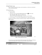
...the following menu bar with newly recorded data from the menu: Start | Programs | Fluke | Power Log | Power Log Alternatively, double-click Power Log icon shortcut on the instrument before you are using a 1735, turn on your PC. 2. The Power Log software welcome screen shown in Figure 1... displays briefly during the launch sequence. The Power Log main menu displays the communications port (COM1) and menu options. Starting Power Log To use the software: 1. Figure...
...the following menu bar with newly recorded data from the menu: Start | Programs | Fluke | Power Log | Power Log Alternatively, double-click Power Log icon shortcut on the instrument before you are using a 1735, turn on your PC. 2. The Power Log software welcome screen shown in Figure 1... displays briefly during the launch sequence. The Power Log main menu displays the communications port (COM1) and menu options. Starting Power Log To use the software: 1. Figure...
FE PowerLog Users Manual
Page 12
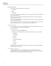
... Connections" for more menu options become available, and some, if not relevant, are unavailable, depending on which instrument you are using the data. Depending on the measured or saved data. Power Log Users Manual Main Menu Options The initial menu presents options for... the following: • Download • Open • Print Setup Once you have downloaded data into Power Log, more information about using , the window opens a series of tabs: • Summary • Spreadsheet • RMS • Statistics • Frequency/Unbalance • Power...
... Connections" for more menu options become available, and some, if not relevant, are unavailable, depending on which instrument you are using the data. Depending on the measured or saved data. Power Log Users Manual Main Menu Options The initial menu presents options for... the following: • Download • Open • Print Setup Once you have downloaded data into Power Log, more information about using , the window opens a series of tabs: • Summary • Spreadsheet • RMS • Statistics • Frequency/Unbalance • Power...
FE PowerLog Users Manual
Page 13
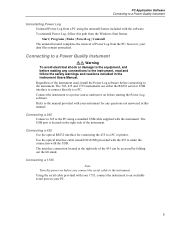
... | Programs | Fluke | PowerLog | Uninstall The uninstall wizard completes the removal of the instrument. Connecting to a Power Quality Instument WX Warning To avoid electrical shock or damage to the equipment, and before connecting to a PC. The USB port is located on your 1735, connect the instrument...before you connect the serial cable to the instrument. Refer to the manual provided with the instrument. The 345, 435 and 1735 instruments use either the RS232 serial or USB interface to connect directly to the instrument. PC Application Software Connecting to a Power Quality ...
... | Programs | Fluke | PowerLog | Uninstall The uninstall wizard completes the removal of the instrument. Connecting to a Power Quality Instument WX Warning To avoid electrical shock or damage to the equipment, and before connecting to a PC. The USB port is located on your 1735, connect the instrument...before you connect the serial cable to the instrument. Refer to the manual provided with the instrument. The 345, 435 and 1735 instruments use either the RS232 serial or USB interface to connect directly to the instrument. PC Application Software Connecting to a Power Quality ...
FE PowerLog Users Manual
Page 14
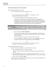
... not download data while the instrument is not already running. The Options menu allows filtering the data using Power Log with the following screen shot become available only after downloading data. The data transfer can transfer... data stored in the instrument to a PC. Note The window that opens defaults to the mode last used, or the mode the instrument was in when the data was recorded. Select a file to the DataFiles... 1. Note that you select Save Data. The menu options in the Fluke > Power Log folder. First, start Power Log if it is still logging; Select File | Open, and ...
... not download data while the instrument is not already running. The Options menu allows filtering the data using Power Log with the following screen shot become available only after downloading data. The data transfer can transfer... data stored in the instrument to a PC. Note The window that opens defaults to the mode last used, or the mode the instrument was in when the data was recorded. Select a file to the DataFiles... 1. Note that you select Save Data. The menu options in the Fluke > Power Log folder. First, start Power Log if it is still logging; Select File | Open, and ...

FE PowerLog Users Manual
Page 15
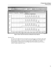
Summary Display for use in other software, such as MS Excel and database programs. Whether downloaded from a connected instrument, or opened from files, the same tabs and window options ... any notes that may be viewed and printed, or exported for User Input eto004.bmp 7 PC Application Software Analyzing Data Analyzing Data Data can be useful. Figure 2.
Summary Display for use in other software, such as MS Excel and database programs. Whether downloaded from a connected instrument, or opened from files, the same tabs and window options ... any notes that may be viewed and printed, or exported for User Input eto004.bmp 7 PC Application Software Analyzing Data Analyzing Data Data can be useful. Figure 2.

FE PowerLog Users Manual
Page 19
Figure 7 shows another way of the display window. 11 PC Application Software Analyzing Data Figure 6. eto008.bmp MAX AVG Figure 7. Histogram powerloghisto.eps Note With either the histogram or Time evolution display, filters may be selected and un-selected as needed using the radio buttons at the top of looking at harmonics data. Harmonics Time Plot with Selected Channels This tab is visible only if you captured relevant harmonics data.
Figure 7 shows another way of the display window. 11 PC Application Software Analyzing Data Figure 6. eto008.bmp MAX AVG Figure 7. Histogram powerloghisto.eps Note With either the histogram or Time evolution display, filters may be selected and un-selected as needed using the radio buttons at the top of looking at harmonics data. Harmonics Time Plot with Selected Channels This tab is visible only if you captured relevant harmonics data.

FE PowerLog Users Manual
Page 20
... the time along the X (vertical) axis, as shown in the example data in Figure 6. The method of calculation used in Figure 9, a legend explains the colors used is the measurement method defined by negative sequence components. Figure 8 shows the display indicating both the time plot and legend ...for the recorded information. Power Log Users Manual Select the Time evolution radio button to change the display to filter the information using the checkboxes at the top of the display window. Frequency/Unbalance Tab Unbalance displays the voltage unbalance (%) in the case of ...
... the time along the X (vertical) axis, as shown in the example data in Figure 6. The method of calculation used in Figure 9, a legend explains the colors used is the measurement method defined by negative sequence components. Figure 8 shows the display indicating both the time plot and legend ...for the recorded information. Power Log Users Manual Select the Time evolution radio button to change the display to filter the information using the checkboxes at the top of the display window. Frequency/Unbalance Tab Unbalance displays the voltage unbalance (%) in the case of ...
FE PowerLog Users Manual
Page 21
PC Application Software Analyzing Data Figure 9. In the example in Figure 10, the power logger in use was recorded, or screens saved by pressing the SAVE button on the top toolbar to Harmonics. Power Time Plot with Active and Reactive Power Selected eto010.bmp Screens Tab The Screens tab illustrates the screen mode in use by the logger or instrument with which the data was the Fluke 1735, and the recording mode set to display additional screens. 13 Use the right and left arrowhead buttons on the Instrument.
PC Application Software Analyzing Data Figure 9. In the example in Figure 10, the power logger in use was recorded, or screens saved by pressing the SAVE button on the top toolbar to Harmonics. Power Time Plot with Active and Reactive Power Selected eto010.bmp Screens Tab The Screens tab illustrates the screen mode in use by the logger or instrument with which the data was the Fluke 1735, and the recording mode set to display additional screens. 13 Use the right and left arrowhead buttons on the Instrument.

FE PowerLog Users Manual
Page 23
...The Print dialog box allows you to configure your selected printer. Report Writer Assistant Selection Options eto013.bmp 2. Select Initial Date/Time using the Group Interval selection box, with these steps: 1. Figure 12. Deselect any of the selected options in other Properties). 15 Limit the... time interval using the selection box in the upper right of the dialog box. 4. Click O.K. PC Application Software Printing Reports and Exporting Data Printing...
...The Print dialog box allows you to configure your selected printer. Report Writer Assistant Selection Options eto013.bmp 2. Select Initial Date/Time using the Group Interval selection box, with these steps: 1. Figure 12. Deselect any of the selected options in other Properties). 15 Limit the... time interval using the selection box in the upper right of the dialog box. 4. Click O.K. PC Application Software Printing Reports and Exporting Data Printing...

FE PowerLog Users Manual
Page 24
... a spreadsheet. Open a measurement data file, File | Export. Avoid errors in data exporting by limiting the date intervals if you can deselect any of the fields using the checkboxes at the bottom of data that can be exported, as well as type" field remains empty, with MS Excel®. 2. The "Save as...
... a spreadsheet. Open a measurement data file, File | Export. Avoid errors in data exporting by limiting the date intervals if you can deselect any of the fields using the checkboxes at the bottom of data that can be exported, as well as type" field remains empty, with MS Excel®. 2. The "Save as...
Fluke 1735 Three Phase Power Logger Datasheet
Page 2
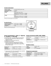
...devices Harmonics measurements - With memory for up to 15 A, 150 A, or 3000 A for extended periods. Easily customize the report. 2 Fluke Corporation 1735 Three-Phase Power Logger Create professional reports. These variable range current probes are correct, and then logging begins when you press the RECORD .... quantify energy consumption before adding loads Energy assessments - verify electrical system capacity before , and after improvements, to use The four current probes are single leads, enabling easy and quick setups. Capture voltage events using user-defined thresholds.
...devices Harmonics measurements - With memory for up to 15 A, 150 A, or 3000 A for extended periods. Easily customize the report. 2 Fluke Corporation 1735 Three-Phase Power Logger Create professional reports. These variable range current probes are correct, and then logging begins when you press the RECORD .... quantify energy consumption before adding loads Energy assessments - verify electrical system capacity before , and after improvements, to use The four current probes are single leads, enabling easy and quick setups. Capture voltage events using user-defined thresholds.

Fluke 1735 Three Phase Power Logger Datasheet
Page 3
... per °C from the reference Refers to operating temperature range, max. Temperature coefficient Intrinsic error Operating error Climatic class Housing ± 0.1 % of m. v. + 10 digit) 0.1 V 3 Fluke Corporation 1735 Three-Phase Power Logger Refers to reference temperature, max. EN60529 (refers only to the main housing without the battery compartment) RMS values are defined in...
... per °C from the reference Refers to operating temperature range, max. Temperature coefficient Intrinsic error Operating error Climatic class Housing ± 0.1 % of m. v. + 10 digit) 0.1 V 3 Fluke Corporation 1735 Three-Phase Power Logger Refers to reference temperature, max. EN60529 (refers only to the main housing without the battery compartment) RMS values are defined in...
Fluke 1735 Three Phase Power Logger Datasheet
Page 4
...Power factor) Intrinsic error Resolution Operating error ± (0.7 % of m.v. + 15 digit) 1 kW ± (1.5 % of m.v.+ 10 digit) 0.01 Hz 4 Fluke Corporation 1735 Three-Phase Power Logger conductor lock Flexi Set-Lock Power measurement (P - v. + 10 digit) Operating error: ± (1 % of m. Distorting) v Measuring range:...v Maximum range with voltage range 230 V wye connection and 150 A current range is 2.490 MW, higher displayed values possible when using Flexi Set please make sure to position the conductor opposite to the Flexi Set-lock (refer following figure). Active, S - v....
...Power factor) Intrinsic error Resolution Operating error ± (0.7 % of m.v. + 15 digit) 1 kW ± (1.5 % of m.v.+ 10 digit) 0.01 Hz 4 Fluke Corporation 1735 Three-Phase Power Logger conductor lock Flexi Set-Lock Power measurement (P - v. + 10 digit) Operating error: ± (1 % of m. Distorting) v Measuring range:...v Maximum range with voltage range 230 V wye connection and 150 A current range is 2.490 MW, higher displayed values possible when using Flexi Set please make sure to position the conductor opposite to the Flexi Set-lock (refer following figure). Active, S - v....

User Manual
Page 2
...Shipping Point). clusions of a defective product which , in material and workmanship under normal use outside the product's specified rating, or normal wear and tear of mechanical components, Fluke will not affect the validity or enforceability of repair/replacement parts when product purchased in... SPECIAL, INDIRECT, INCIDENTAL OR CONSEQUENTIAL DAMAGES OR LOSSES, INCLUDING LOSS OF DATA, ARISING FROM ANY CAUSE OR THEORY. Fluke Corporation P.O. Fluke Europe B.V. Warranty support is available only if product is two years and begins on non-defective media. Since some ...
...Shipping Point). clusions of a defective product which , in material and workmanship under normal use outside the product's specified rating, or normal wear and tear of mechanical components, Fluke will not affect the validity or enforceability of repair/replacement parts when product purchased in... SPECIAL, INDIRECT, INCIDENTAL OR CONSEQUENTIAL DAMAGES OR LOSSES, INCLUDING LOSS OF DATA, ARISING FROM ANY CAUSE OR THEORY. Fluke Corporation P.O. Fluke Europe B.V. Warranty support is available only if product is two years and begins on non-defective media. Since some ...
User Manual
Page 3
Table of Contents Title Page Introduction 1 Contacting Fluke 1 Symbols 2 Safety Instructions 3 Standard and Optional Accessories 5 Software and Information CD-ROM 7 Instrument Familiarity 7 Current Probes 7 Control Elements, Display 7 Display Symbols 8 Description of the Control Elements 9 Using the SAVE and CURSOR Keys 10 Connectors 11 USB Interface 11 Installing the USB Driver 11 Basic Adjustments...
Table of Contents Title Page Introduction 1 Contacting Fluke 1 Symbols 2 Safety Instructions 3 Standard and Optional Accessories 5 Software and Information CD-ROM 7 Instrument Familiarity 7 Current Probes 7 Control Elements, Display 7 Display Symbols 8 Description of the Control Elements 9 Using the SAVE and CURSOR Keys 10 Connectors 11 USB Interface 11 Installing the USB Driver 11 Basic Adjustments...
User Manual
Page 4
1735 Users Manual Overview 23 Meter Volts / Amps / Hz 23 Scope 23 Harmonics 23 Power 23 Events 24 Connecting the Power Logger to the Network 24 ... 45 Measurement 45 Save 46 Power Log PC Software 46 Installing Power Log Software 46 Starting Power Log 46 Using Power Log 47 Energy Recording with Fluke Power Log 49 Recording Power (Demand) with 1735 Power Logger 51 Inside the Logger 52 Line Power or Battery Mode 52 Replacing the Battery Pack 52...
1735 Users Manual Overview 23 Meter Volts / Amps / Hz 23 Scope 23 Harmonics 23 Power 23 Events 24 Connecting the Power Logger to the Network 24 ... 45 Measurement 45 Save 46 Power Log PC Software 46 Installing Power Log Software 46 Starting Power Log 46 Using Power Log 47 Energy Recording with Fluke Power Log 49 Recording Power (Demand) with 1735 Power Logger 51 Inside the Logger 52 Line Power or Battery Mode 52 Replacing the Battery Pack 52...

User Manual
Page 9
...; Connections-Blondel (Aron, Three-Element Delta) ...32 11. List of Voltage and Current 48 13. Power Logger Connectors 11 4. Fluke Power Log Screen 47 12. Split Phase Connections 29 8. Display Symbols 8 2. Three-Phase Delta Δ Connections-Blondel (Aron, Two-Element Delta)... ...31 10. Fluke Power Log Displaying Three Phases of Figures Figure Title Page 1. Control Elements 9 3. Using the Optional Mini Clamps 25 6. Three-Phase Wye Connections 30 9. Replacing the Battery Pack 53 vii
...; Connections-Blondel (Aron, Three-Element Delta) ...32 11. List of Voltage and Current 48 13. Power Logger Connectors 11 4. Fluke Power Log Screen 47 12. Split Phase Connections 29 8. Display Symbols 8 2. Three-Phase Delta Δ Connections-Blondel (Aron, Two-Element Delta)... ...31 10. Fluke Power Log Displaying Three Phases of Figures Figure Title Page 1. Control Elements 9 3. Using the Optional Mini Clamps 25 6. Three-Phase Wye Connections 30 9. Replacing the Battery Pack 53 vii


