
User Manual
Page 2
... the work. Box 9090 Everett, WA 98206-9090 U.S.A. Fluke warrants that it has been properly recorded on new and unused products to any provision of the difficulty, postage and insurance prepaid (FOB Destination). Warranty support is available only if product is submitted for importation costs of repair/replacement parts when product purchased in another country. To obtain warranty service, contact...
... the work. Box 9090 Everett, WA 98206-9090 U.S.A. Fluke warrants that it has been properly recorded on new and unused products to any provision of the difficulty, postage and insurance prepaid (FOB Destination). Warranty support is available only if product is submitted for importation costs of repair/replacement parts when product purchased in another country. To obtain warranty service, contact...

User Manual
Page 4
... Regional Voltage 2-3 Connect to Mains Power 2-4 Set the Handle Position 2-5 Power On and Standby 2-6 Warm-Up the Product 2-7 Configure the Product 2-7 Input Module and Relay Card Installation 2-8 Set Up Security 2-11 Input and Channel Configuration 3-1 Introduction...3-3 Input Wiring...3-3 The Universal Input Module 3-3 Wiring Safety and Considerations 3-4 3-Wire and 4-Wire Sense Input Configuration 3-5 Input Types and Wiring Diagrams 3-6 Input Wiring Instructions 3-7 Channel Configuration 3-9 About Channel Numbers 3-9 Basic Channel Operations 3-11 Open the Channel Setup...
... Regional Voltage 2-3 Connect to Mains Power 2-4 Set the Handle Position 2-5 Power On and Standby 2-6 Warm-Up the Product 2-7 Configure the Product 2-7 Input Module and Relay Card Installation 2-8 Set Up Security 2-11 Input and Channel Configuration 3-1 Introduction...3-3 Input Wiring...3-3 The Universal Input Module 3-3 Wiring Safety and Considerations 3-4 3-Wire and 4-Wire Sense Input Configuration 3-5 Input Types and Wiring Diagrams 3-6 Input Wiring Instructions 3-7 Channel Configuration 3-9 About Channel Numbers 3-9 Basic Channel Operations 3-11 Open the Channel Setup...

User Manual
Page 5
... Change 3-33 NPLC ...3-34 Input Impedance 3-34 Bandwidth ...3-34 Display As ...3-34 Open Detect 3-34 4 Scan/Monitor, Record, and Data 4-1 Introduction...4-3 Scan...4-3 About Scan Timing and Sampling 4-5 Configure a Scan 4-7 Trigger Type 4-8 Auto Recording 4-9 File Destination 4-9 Sample Rate 4-9 Data Security 4-10 Temperature Unit 4-11 Align Channels 4-11 Automatic Power Loss Scan Resume 4-12 Basic Scan Procedures 4-12 Start a Scan 4-12 View Scan Data...
... Change 3-33 NPLC ...3-34 Input Impedance 3-34 Bandwidth ...3-34 Display As ...3-34 Open Detect 3-34 4 Scan/Monitor, Record, and Data 4-1 Introduction...4-3 Scan...4-3 About Scan Timing and Sampling 4-5 Configure a Scan 4-7 Trigger Type 4-8 Auto Recording 4-9 File Destination 4-9 Sample Rate 4-9 Data Security 4-10 Temperature Unit 4-11 Align Channels 4-11 Automatic Power Loss Scan Resume 4-12 Basic Scan Procedures 4-12 Start a Scan 4-12 View Scan Data...
User Manual
Page 7
Current and Voltage Channel Configuration 3-18 3-5. Thermistor Channel Setup 3-22 3-9. PRT Channel Setup 3-23 3-10. Statistics ...5-6 6-1. Rear-Panel Features 1-6 1-3. Channel Types and Numbers 3-9 3-3. Math Channel Formulas 3-27 3-12. Scan Sample Rates 4-10 4-4. User-Replaceable Parts and Accessories 6-5 7-1. Instrument Setup Menu 2-7 3-1. Totalizer Channel Configuration 3-26 3-11. Scan Statistics...4-14 4-5. Fuses...2-3 2-2. The Scan Menu ...4-4 4-2. Error Messages...7-3 7-2. Front-Panel Features 1-4 1-2. Resistance Channel Configuration 3-19 ...
Current and Voltage Channel Configuration 3-18 3-5. Thermistor Channel Setup 3-22 3-9. PRT Channel Setup 3-23 3-10. Statistics ...5-6 6-1. Rear-Panel Features 1-6 1-3. Channel Types and Numbers 3-9 3-3. Math Channel Formulas 3-27 3-12. Scan Sample Rates 4-10 4-4. User-Replaceable Parts and Accessories 6-5 7-1. Instrument Setup Menu 2-7 3-1. Totalizer Channel Configuration 3-26 3-11. Scan Statistics...4-14 4-5. Fuses...2-3 2-2. The Scan Menu ...4-4 4-2. Error Messages...7-3 7-2. Front-Panel Features 1-4 1-2. Resistance Channel Configuration 3-19 ...

User Manual
Page 15
... Relay Card Installation" in data menus and also change the view of the softkey changes with each menu and is flashing. Front-Panel USB Port USB port to insert a USB drive. This date and time is used for more information and operation instructions. 1-5 Scan all active channels directed by the test setup file. Visually shows how many and which slots the Input Modules are connected to...
... Relay Card Installation" in data menus and also change the view of the softkey changes with each menu and is flashing. Front-Panel USB Port USB port to insert a USB drive. This date and time is used for more information and operation instructions. 1-5 Scan all active channels directed by the test setup file. Visually shows how many and which slots the Input Modules are connected to...

User Manual
Page 16
... or "0" key to wire and configure a channel. See "Set the Regional Voltage" in Chapter 2. See Chapter 5 for more information and operation instructions. Channel Setup is powered on how to take a screenshot of the display. Rear-Panel Features 11 3 12345 67 8 12345 6 4 5 6 7 8 9 10 hce002.eps Item Name Line Voltage Selector and Fuse Function Regional voltage selector. Manage setup files, scan data files, and DMM...
... or "0" key to wire and configure a channel. See "Set the Regional Voltage" in Chapter 2. See Chapter 5 for more information and operation instructions. Channel Setup is powered on how to take a screenshot of the display. Rear-Panel Features 11 3 12345 67 8 12345 6 4 5 6 7 8 9 10 hce002.eps Item Name Line Voltage Selector and Fuse Function Regional voltage selector. Manage setup files, scan data files, and DMM...

User Manual
Page 17
... Rear-Panel Overview Table 1-2. Rear-Panel Features (cont.) Item Name Main Power Switch Mains Power Connector Chassis Ground Serial USB Port LAN Connection Totalizer Input DIO (Digital I/O Input Ports) Function Supplies and disconnects mains power to the chassis. Terminal that accept the Input Modules. USB port used for remote operation. Network port used for the Totalizer feature. See Scan Test Setup" in a system, this...
... Rear-Panel Overview Table 1-2. Rear-Panel Features (cont.) Item Name Main Power Switch Mains Power Connector Chassis Ground Serial USB Port LAN Connection Totalizer Input DIO (Digital I/O Input Ports) Function Supplies and disconnects mains power to the chassis. Terminal that accept the Input Modules. USB port used for remote operation. Network port used for the Totalizer feature. See Scan Test Setup" in a system, this...
User Manual
Page 18
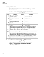
... utilization points (socket outlets and similar points) of danger. A Caution identifies conditions and procedures that can cause damage to the equipment types in this manual and on the Product. Important information. Measurement Category II is applicable to test and measuring circuits connected directly to the user. Symbols Symbol Description Symbol Description Risk of the low-voltage MAINS installation. See manual...
... utilization points (socket outlets and similar points) of danger. A Caution identifies conditions and procedures that can cause damage to the equipment types in this manual and on the Product. Important information. Measurement Category II is applicable to test and measuring circuits connected directly to the user. Symbols Symbol Description Symbol Description Risk of the low-voltage MAINS installation. See manual...

User Manual
Page 19
... the mains power cord is connected to a protective earth ground. Look for damaged insulation and measure a known voltage. • Do not exceed the Measurement Category (CAT) rating of the lowest rated individual component of wear. • Make sure the ground conductor in the mains power cord is blocked. • Use only correct measurement category (CAT), voltage, and amperage rated probes, test leads, and adapters for...
... the mains power cord is connected to a protective earth ground. Look for damaged insulation and measure a known voltage. • Do not exceed the Measurement Category (CAT) rating of the lowest rated individual component of wear. • Make sure the ground conductor in the mains power cord is blocked. • Use only correct measurement category (CAT), voltage, and amperage rated probes, test leads, and adapters for...

User Manual
Page 21
... clean the Product and replace the fuse in the rear of the Product. • Chapter 7 supplies information on error messages and how to keep the Product within specifications. • The 2638A Product CD contains the all the manuals in the manual set includes: • This 2638A Users Manual that contains feature information, operation instructions, and basic user maintenance and troubleshooting information. The Users Manual is translated into...
... clean the Product and replace the fuse in the rear of the Product. • Chapter 7 supplies information on error messages and how to keep the Product within specifications. • The 2638A Product CD contains the all the manuals in the manual set includes: • This 2638A Users Manual that contains feature information, operation instructions, and basic user maintenance and troubleshooting information. The Users Manual is translated into...
User Manual
Page 22
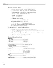
... view, print, or download the latest manual supplement, visit http://us.fluke.com/usen/support/manuals. Send the Product to Fluke for calibration or repair: 1. Calibration and Repair Information To schedule and send the Product to the Service Center. Pack and secure the Product in a shipment box with a minimum of 2 inches of the following telephone numbers: • Technical Support USA: 1-800-44-FLUKE...
... view, print, or download the latest manual supplement, visit http://us.fluke.com/usen/support/manuals. Send the Product to Fluke for calibration or repair: 1. Calibration and Repair Information To schedule and send the Product to the Service Center. Pack and secure the Product in a shipment box with a minimum of 2 inches of the following telephone numbers: • Technical Support USA: 1-800-44-FLUKE...

User Manual
Page 23
... Operations sum, difference, multiply, divide, polynomial, power, square root, reciprocal, exponential, logarithm, absolute value, average, maximum, minimum Triggers interval, external (trigger input), alarm, remote (bus), manual Battery life 5 years Memory Scan data RAM 75,000 readings with timestamp Data/Setup flash memory 20 MB Non-volatile memory life 5 years USB Host Port Standard 2.0, full speed Connector type Type A Function Memory File system FAT32 Memory capacity 32 GB USB...
... Operations sum, difference, multiply, divide, polynomial, power, square root, reciprocal, exponential, logarithm, absolute value, average, maximum, minimum Triggers interval, external (trigger input), alarm, remote (bus), manual Battery life 5 years Memory Scan data RAM 75,000 readings with timestamp Data/Setup flash memory 20 MB Non-volatile memory life 5 years USB Host Port Standard 2.0, full speed Connector type Type A Function Memory File system FAT32 Memory capacity 32 GB USB...

User Manual
Page 37
... use before mains power is equipped with a voltage selector that must be set for the region of use . See Chapter 6 for instructions on how to 100 V, 120 V, 220 V, or 240 V. Fuse Replacement and Line-Voltage Selection hce016.eps 2-3 Table 2-1. Set the Regional Voltage The Product is connected. 1 2 Figure 2-1. Each voltage selection requires a specific fuse. The selector can be set to set the voltage selector. Fuses Voltage Selector Fuse Fluke Part Number...
... use before mains power is equipped with a voltage selector that must be set for the region of use . See Chapter 6 for instructions on how to 100 V, 120 V, 220 V, or 240 V. Fuse Replacement and Line-Voltage Selection hce016.eps 2-3 Table 2-1. Set the Regional Voltage The Product is connected. 1 2 Figure 2-1. Each voltage selection requires a specific fuse. The selector can be set to set the voltage selector. Fuses Voltage Selector Fuse Fluke Part Number...

User Manual
Page 41
... change a setting, highlight the setting then use to stabilize the environmentally controlled components. Note If the incorrect language is set by accident, push then push . Selections Available English 中文 Français Deutsch Portugués Español 한국어 -- Table 2-2. This temporarily resets the language to show a comma or decimal. Shows the firmware version installed, model number...
... change a setting, highlight the setting then use to stabilize the environmentally controlled components. Note If the incorrect language is set by accident, push then push . Selections Available English 中文 Français Deutsch Portugués Español 한국어 -- Table 2-2. This temporarily resets the language to show a comma or decimal. Shows the firmware version installed, model number...
User Manual
Page 42
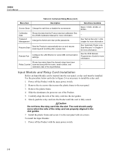
... aluminum slot protector out of the relay card into the slot guides. 6. Remote Port Configure the LAN Ethernet or serial USB communication settings. Use the procedure below and refer to Figure 2-6 as necessary to the rear panel with the name, serial number, and calibration date of the relay card are properly aligned in this chapter for more information. Install the plastic...
... aluminum slot protector out of the relay card into the slot guides. 6. Remote Port Configure the LAN Ethernet or serial USB communication settings. Use the procedure below and refer to Figure 2-6 as necessary to the rear panel with the name, serial number, and calibration date of the relay card are properly aligned in this chapter for more information. Install the plastic...
User Manual
Page 58
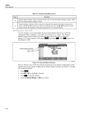
.... 2638A Users Manual Table 3-3. Channel Setup Menu (cont.) Item Function Channel status indicator. When a channel is green. Use and to highlight a channel. 3. When a channel is referred to edit the channel. 4. Push again to set to ON, it is set the channel to ON and configured. If the channel was not previously configured, the default channel settings are...
.... 2638A Users Manual Table 3-3. Channel Setup Menu (cont.) Item Function Channel status indicator. When a channel is green. Use and to highlight a channel. 3. When a channel is referred to edit the channel. 4. Push again to set to ON, it is set the channel to ON and configured. If the channel was not previously configured, the default channel settings are...
User Manual
Page 71
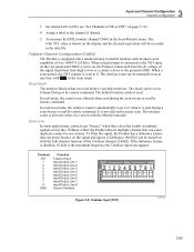
... Product counts each time the dc voltage of the signal transitions from high to low or a contact closes to the channel if desired. 5. 3 Input and Channel Configuration Channel Configuration 3. In read mode, the count is read during the scan sweep or read /reset. The mode can be set to 1048575 (20 bits). Assign a label to the ground (GND).
... Product counts each time the dc voltage of the signal transitions from high to low or a contact closes to the channel if desired. 5. 3 Input and Channel Configuration Channel Configuration 3. In read mode, the count is read during the scan sweep or read /reset. The mode can be set to 1048575 (20 bits). Assign a label to the ground (GND).
User Manual
Page 88
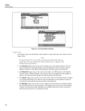
... happen on the Digital I/O port detects a high condition. There are four trigger types: Note If a Scan Count of 0 is set or if the scan interval is shorter than the scan sweep time, the scan continuously repeats until the scan is started by a front-panel softkey in the Scan/Monitor menu. This trigger type lets the user set the number of times to scan...
... happen on the Digital I/O port detects a high condition. There are four trigger types: Note If a Scan Count of 0 is set or if the scan interval is shorter than the scan sweep time, the scan continuously repeats until the scan is started by a front-panel softkey in the Scan/Monitor menu. This trigger type lets the user set the number of times to scan...

User Manual
Page 133
... and connected to the Product is malfunctioning. DO NOT replace the fuse with likely causes and solutions. Cause 2: AC mains power. Solution 2: Make sure the circuit that the Product functions abnormally, Table 7-2 can help find and solve the problem. Cause 2: Screen saver activated. Cause 2: Relay card not installed. Be sure to have the instrument model number, serial number, and regional voltage...
... and connected to the Product is malfunctioning. DO NOT replace the fuse with likely causes and solutions. Cause 2: AC mains power. Solution 2: Make sure the circuit that the Product functions abnormally, Table 7-2 can help find and solve the problem. Cause 2: Screen saver activated. Cause 2: Relay card not installed. Be sure to have the instrument model number, serial number, and regional voltage...
User Manual
Page 134
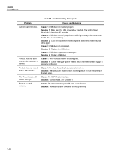
... Cause: The internal memory or USB drive is properly configured. Product is started. Solution: Contact Fluke. Solution 3: Replace the USB drive. Product does not record when I start recording or turn on . 2638A Users Manual Problem Cannot read USB drive. Product does not start to be triggered. Troubleshooting Chart (cont.) Causes and Solutions Cause 1: USB drive not installed properly. Cause 4: USB drive inoperative or damaged. Solution 4: Replace USB drive. Cause 1: The Product...
... Cause: The internal memory or USB drive is properly configured. Product is started. Solution: Contact Fluke. Solution 3: Replace the USB drive. Product does not record when I start recording or turn on . 2638A Users Manual Problem Cannot read USB drive. Product does not start to be triggered. Troubleshooting Chart (cont.) Causes and Solutions Cause 1: USB drive not installed properly. Cause 4: USB drive inoperative or damaged. Solution 4: Replace USB drive. Cause 1: The Product...


