User Manual
Page 1
All product names are subject to change without notice. Specifications are trademarks of their respective companies. All rights reserved. 2638A HYDRA Series III Data Acquisition Unit Users Manual June 2013 © 2013 Fluke Corporation.
All product names are subject to change without notice. Specifications are trademarks of their respective companies. All rights reserved. 2638A HYDRA Series III Data Acquisition Unit Users Manual June 2013 © 2013 Fluke Corporation.

User Manual
Page 3
... Page 1 Product Overview and Specifications 1-1 Introduction...1-3 Product Overview 1-3 Front and Rear-Panel Overview 1-4 Safety Information 1-8 Screen Capture Feature 1-10 About this Manual 1-11 The Product Manual Set 1-11 How to Contact Fluke 1-12 Calibration and Repair Information 1-12 General Specifications 1-12 Measurement Specifications 1-14 DC Voltage ...1-14 DC Voltage Input Characteristics 1-14 DC...
... Page 1 Product Overview and Specifications 1-1 Introduction...1-3 Product Overview 1-3 Front and Rear-Panel Overview 1-4 Safety Information 1-8 Screen Capture Feature 1-10 About this Manual 1-11 The Product Manual Set 1-11 How to Contact Fluke 1-12 Calibration and Repair Information 1-12 General Specifications 1-12 Measurement Specifications 1-14 DC Voltage ...1-14 DC Voltage Input Characteristics 1-14 DC...

User Manual
Page 4
2638A Users Manual 2 3 RTD ...1-20 RTD Temperature Accuracy 1-20 RTD Measurement Characteristics 1-20 Thermistor ...1-20 Thermistor Temperature Accuracy 1-20 Thermistor Measurement Characteristics 1-21 Thermocouple 1-21 Thermocouple Temperature Accuracy 1-21 Thermocouple Measurement Characteristics 1-23 Digital I/O...1-23 Totalizer...1-23 Trigger ...1-23 Alarm Output 1-23 2638A-100 Universal Input Module 1-23 General ...1-23 Initial Setup and Configuration...
2638A Users Manual 2 3 RTD ...1-20 RTD Temperature Accuracy 1-20 RTD Measurement Characteristics 1-20 Thermistor ...1-20 Thermistor Temperature Accuracy 1-20 Thermistor Measurement Characteristics 1-21 Thermocouple 1-21 Thermocouple Temperature Accuracy 1-21 Thermocouple Measurement Characteristics 1-23 Digital I/O...1-23 Totalizer...1-23 Trigger ...1-23 Alarm Output 1-23 2638A-100 Universal Input Module 1-23 General ...1-23 Initial Setup and Configuration...

User Manual
Page 6
2638A Users Manual 7 Error Messages and Troubleshooting 7-1 Introduction...7-3 Error Messages 7-3 Troubleshooting 7-19 iv
2638A Users Manual 7 Error Messages and Troubleshooting 7-1 Introduction...7-3 Error Messages 7-3 Troubleshooting 7-19 iv

User Manual
Page 8
2638A Users Manual vi
2638A Users Manual vi

User Manual
Page 10
2638A Users Manual viii
2638A Users Manual viii

User Manual
Page 11
... Overview and Specifications Title Page Introduction...1-3 Product Overview 1-3 Front and Rear-Panel Overview 1-4 Safety Information 1-8 Screen Capture Feature 1-10 About this Manual 1-11 The Product Manual Set 1-11 How to Contact Fluke 1-12 Calibration and Repair Information 1-12 General Specifications 1-12 Measurement Specifications 1-14 DC Voltage ...1-14 DC Voltage Input Characteristics 1-14 DC...
... Overview and Specifications Title Page Introduction...1-3 Product Overview 1-3 Front and Rear-Panel Overview 1-4 Safety Information 1-8 Screen Capture Feature 1-10 About this Manual 1-11 The Product Manual Set 1-11 How to Contact Fluke 1-12 Calibration and Repair Information 1-12 General Specifications 1-12 Measurement Specifications 1-14 DC Voltage ...1-14 DC Voltage Input Characteristics 1-14 DC...

User Manual
Page 12
2638A Users Manual Thermistor Measurement Characteristics 1-21 Thermocouple 1-21 Thermocouple Temperature Accuracy 1-21 Thermocouple Measurement Characteristics 1-23 Digital I/O...1-23 Totalizer...1-23 Trigger ...1-23 Alarm Output 1-23 2638A-100 Universal Input Module 1-23 General ...1-23 1-2
2638A Users Manual Thermistor Measurement Characteristics 1-21 Thermocouple 1-21 Thermocouple Temperature Accuracy 1-21 Thermocouple Measurement Characteristics 1-23 Digital I/O...1-23 Totalizer...1-23 Trigger ...1-23 Alarm Output 1-23 2638A-100 Universal Input Module 1-23 General ...1-23 1-2
User Manual
Page 13
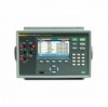
A scan can be manually controlled from the rear-panel alarm output for up to 67 analog channels per scan sweep. While ... (HI) or lower (LO) range has been exceeded. When the DIO channel is included in scan. Product Overview The Fluke Calibration 2638A HYDRA Series III Data Acquisition Unit (the Product or Instrument) is a 67 analog channel bench-top data logger that can ...port is read. 1-3 1 Product Overview and Specifications Introduction Introduction This chapter supplies information about the Product, the manual set, safety information, contact information, and specifications.
A scan can be manually controlled from the rear-panel alarm output for up to 67 analog channels per scan sweep. While ... (HI) or lower (LO) range has been exceeded. When the DIO channel is included in scan. Product Overview The Fluke Calibration 2638A HYDRA Series III Data Acquisition Unit (the Product or Instrument) is a 67 analog channel bench-top data logger that can ...port is read. 1-3 1 Product Overview and Specifications Introduction Introduction This chapter supplies information about the Product, the manual set, safety information, contact information, and specifications.

User Manual
Page 14
... connection. Front and Rear-Panel Overview Table 1-1 identifies and describes the front-panel features and Table 1-2 identifies and describes the rear-panel features. Table 1-1. 2638A Users Manual • Totalizer - Standby mode also disables remote operation. To visualize trend data, the DMM provides additional functionality to the totalizer input terminals on the display...
... connection. Front and Rear-Panel Overview Table 1-1 identifies and describes the front-panel features and Table 1-2 identifies and describes the rear-panel features. Table 1-1. 2638A Users Manual • Totalizer - Standby mode also disables remote operation. To visualize trend data, the DMM provides additional functionality to the totalizer input terminals on the display...

User Manual
Page 16
... PRINT or "0" key to customize the Product. See "Set the Regional Voltage" in Chapter 2. In addition to wire and configure a channel. Configure and verify channels. 2638A Users Manual Item Name Record Memory DMM Instrument Setup Channel Setup Numeric Keypad 1 2 Table 1-1. See Chapter 5 for more information and...
... PRINT or "0" key to customize the Product. See "Set the Regional Voltage" in Chapter 2. In addition to wire and configure a channel. Configure and verify channels. 2638A Users Manual Item Name Record Memory DMM Instrument Setup Channel Setup Numeric Keypad 1 2 Table 1-1. See Chapter 5 for more information and...
User Manual
Page 18
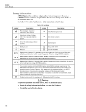
2638A Users Manual Safety Information A Warning identifies conditions and procedures that are dangerous to the Product or the equipment under test. See manual. AC (Alternating Current) Hazardous voltage. Measurement Category III is applicable to test and measuring circuits connected directly to Fluke's website...in domestic household waste. Do not dispose of this electrical/electronic product in the WEEE Directive Annex I, this manual and on the Product. A Caution identifies conditions and procedures that you use the Product. • Carefully read all ...
2638A Users Manual Safety Information A Warning identifies conditions and procedures that are dangerous to the Product or the equipment under test. See manual. AC (Alternating Current) Hazardous voltage. Measurement Category III is applicable to test and measuring circuits connected directly to Fluke's website...in domestic household waste. Do not dispose of this electrical/electronic product in the WEEE Directive Annex I, this manual and on the Product. A Caution identifies conditions and procedures that you use the Product. • Carefully read all ...

User Manual
Page 20
... and connect it directly to the USB drive. 2638A Users Manual • Consider all accessible channels to be hazardous live and an electric shock hazard if any channel is opened. • Use the correct terminals, function, and range for measurements. • Use this path: \\fluke\2638A\[Product Serial Number]\Image PRINT = 3 seconds Figure 1-1. Remove...
... and connect it directly to the USB drive. 2638A Users Manual • Consider all accessible channels to be hazardous live and an electric shock hazard if any channel is opened. • Use the correct terminals, function, and range for measurements. • Use this path: \\fluke\2638A\[Product Serial Number]\Image PRINT = 3 seconds Figure 1-1. Remove...

User Manual
Page 21
... and adjustment procedures to clean the Product and replace the fuse in the manual set includes: • This 2638A Users Manual that contains feature information, operation instructions, and basic user maintenance and troubleshooting information. All manuals are online at http://www.fluke.com/ and on error messages and how to remotely operate the Product. The...
... and adjustment procedures to clean the Product and replace the fuse in the manual set includes: • This 2638A Users Manual that contains feature information, operation instructions, and basic user maintenance and troubleshooting information. All manuals are online at http://www.fluke.com/ and on error messages and how to remotely operate the Product. The...
User Manual
Page 22
... product, visit http://register.fluke.com. Calibration and Repair Information To schedule and send the Product to Contact Fluke To contact Fluke, call one of packing around the Product to 28 °C 2638A Users Manual How to Fluke for calibration or repair: 1. Contact the Fluke Service Center in the world...: +1-425-446-5500 Or, visit Fluke's website at www.fluke.com. Send the ...
... product, visit http://register.fluke.com. Calibration and Repair Information To schedule and send the Product to Contact Fluke To contact Fluke, call one of packing around the Product to 28 °C 2638A Users Manual How to Fluke for calibration or repair: 1. Contact the Fluke Service Center in the world...: +1-425-446-5500 Or, visit Fluke's website at www.fluke.com. Send the ...

User Manual
Page 23
... Operations sum, difference, multiply, divide, polynomial, power, square root, reciprocal, exponential, logarithm, absolute value, average, maximum, minimum Triggers interval, external (trigger input), alarm, remote (bus), manual Battery life 5 years Memory Scan data RAM 75,000 readings with maximum transient voltage of 1000 V peak. 1 Product Overview and Specifications General Specifications Channel Capacity...
... Operations sum, difference, multiply, divide, polynomial, power, square root, reciprocal, exponential, logarithm, absolute value, average, maximum, minimum Triggers interval, external (trigger input), alarm, remote (bus), manual Battery life 5 years Memory Scan data RAM 75,000 readings with maximum transient voltage of 1000 V peak. 1 Product Overview and Specifications General Specifications Channel Capacity...

User Manual
Page 24
... mV 1 mV 100 μV 10 MΩ ±1 % 300 V 300.000 V 100 mV 10 mV 1 mV 10 MΩ ±1 % [1] - Input beyond ±12 V is clamped. 2638A Users Manual Measurement Specifications Accuracy specifications generally are relative to calibration standards and assume a controlled electromagnetic environment per channel) Display Resolution 4 ½ to 6 ½ digits, depending on...
... mV 1 mV 100 μV 10 MΩ ±1 % 300 V 300.000 V 100 mV 10 mV 1 mV 10 MΩ ±1 % [1] - Input beyond ±12 V is clamped. 2638A Users Manual Measurement Specifications Accuracy specifications generally are relative to calibration standards and assume a controlled electromagnetic environment per channel) Display Resolution 4 ½ to 6 ½ digits, depending on...

User Manual
Page 26
... 0.05 % 0.6 % + 0.08 % 0.11 % + 0.05 % 0.22 % + 0.05 % 0.6 % + 0.08 % 0.11 % + 0.05 % 0.22 % + 0.05 % 0.6 % + 0.08 % 0.11 % + 0.05 % 0.22 % + 0.05 % 0.6 % + 0.08 % 0.11 % + 0.05 % 0.22 % + 0.05 % 0.6 % + 0.27 % 0.11 % + 0.05 % 0.22 % + 0.05 % 0.6 % + 0.08 % 0.11 % + 0.05 % 0.22 % + 0.05 % 0.6 % + 0.08 % 0.11 % + 0.05 % 0.22 % + 0.05 % 0.6 % + 0.08 % 0.11 % + 0.05 % 0.22 % + 0.05 % 0.6 % + 0.08 % 0.11 % + 0.05 % 0.22 % + 0.05 % 0.6 % + 0.27 % T.C./ °C Outside 18 °C to 1 kHz >1 kHz 20 Hz 0 % 0 % 0 % 0 % 0 % AC Filter 200 Hz − 0.55 % 0.2 % 0.02 % 0 % 1-16 2638A Users Manual...
... 0.05 % 0.6 % + 0.08 % 0.11 % + 0.05 % 0.22 % + 0.05 % 0.6 % + 0.08 % 0.11 % + 0.05 % 0.22 % + 0.05 % 0.6 % + 0.08 % 0.11 % + 0.05 % 0.22 % + 0.05 % 0.6 % + 0.08 % 0.11 % + 0.05 % 0.22 % + 0.05 % 0.6 % + 0.27 % 0.11 % + 0.05 % 0.22 % + 0.05 % 0.6 % + 0.08 % 0.11 % + 0.05 % 0.22 % + 0.05 % 0.6 % + 0.08 % 0.11 % + 0.05 % 0.22 % + 0.05 % 0.6 % + 0.08 % 0.11 % + 0.05 % 0.22 % + 0.05 % 0.6 % + 0.08 % 0.11 % + 0.05 % 0.22 % + 0.05 % 0.6 % + 0.27 % T.C./ °C Outside 18 °C to 1 kHz >1 kHz 20 Hz 0 % 0 % 0 % 0 % 0 % AC Filter 200 Hz − 0.55 % 0.2 % 0.02 % 0 % 1-16 2638A Users Manual...

User Manual
Page 28
2638A Users Manual AC Current Input Characteristics Range Resolution 4 ½ Digits Resolution 5 ½ Digits 6 ½ Digits Reference Resistance Burden Voltage 100 μA 1 mA 10 mA 100 mA 100.0000 µA 1.000000 mA 10.00000 mA 100.0000 mA 10 nA 100 nA 1 μA 10 μA 1 nA 10 nA 100 nA 1 μA 0.1 nA 1 nA 10 nA 100 nA 1 kΩ 1 kΩ 10 Ω 10 Ω
2638A Users Manual AC Current Input Characteristics Range Resolution 4 ½ Digits Resolution 5 ½ Digits 6 ½ Digits Reference Resistance Burden Voltage 100 μA 1 mA 10 mA 100 mA 100.0000 µA 1.000000 mA 10.00000 mA 100.0000 mA 10 nA 100 nA 1 μA 10 μA 1 nA 10 nA 100 nA 1 μA 0.1 nA 1 nA 10 nA 100 nA 1 kΩ 1 kΩ 10 Ω 10 Ω

User Manual
Page 30
... Sample Rate Slow 10 PLC Medium 2 PLC Fast 1 PLC RTD Temperature Accuracy Accuracy is for 4-wire 100 Ω nominal RTD, using the slow sample rate. 2638A Users Manual RTD Temperature Range 200 °C to 1200 °C (depending on the sensor) Resistance Range 0 Ω to the accuracy specification if using medium or fast...
... Sample Rate Slow 10 PLC Medium 2 PLC Fast 1 PLC RTD Temperature Accuracy Accuracy is for 4-wire 100 Ω nominal RTD, using the slow sample rate. 2638A Users Manual RTD Temperature Range 200 °C to 1200 °C (depending on the sensor) Resistance Range 0 Ω to the accuracy specification if using medium or fast...