
User Manual
Page 4
... Accuracy 1-20 Thermistor Measurement Characteristics 1-21 Thermocouple 1-21 Thermocouple Temperature Accuracy 1-21 Thermocouple Measurement Characteristics 1-23 Digital I/O...1-23 Totalizer...1-23 Trigger ...1-23 Alarm Output 1-23 2638A-100 Universal Input Module 1-23 General ...1-23 Initial Setup and Configuration 2-1 Introduction...2-3 Set the Regional Voltage 2-3 Connect to Mains Power 2-4 Set the Handle Position 2-5 Power On...
... Accuracy 1-20 Thermistor Measurement Characteristics 1-21 Thermocouple 1-21 Thermocouple Temperature Accuracy 1-21 Thermocouple Measurement Characteristics 1-23 Digital I/O...1-23 Totalizer...1-23 Trigger ...1-23 Alarm Output 1-23 2638A-100 Universal Input Module 1-23 General ...1-23 Initial Setup and Configuration 2-1 Introduction...2-3 Set the Regional Voltage 2-3 Connect to Mains Power 2-4 Set the Handle Position 2-5 Power On...

User Manual
Page 12
2638A Users Manual Thermistor Measurement Characteristics 1-21 Thermocouple 1-21 Thermocouple Temperature Accuracy 1-21 Thermocouple Measurement Characteristics 1-23 Digital I/O...1-23 Totalizer...1-23 Trigger ...1-23 Alarm Output 1-23 2638A-100 Universal Input Module 1-23 General ...1-23 1-2
2638A Users Manual Thermistor Measurement Characteristics 1-21 Thermocouple 1-21 Thermocouple Temperature Accuracy 1-21 Thermocouple Measurement Characteristics 1-23 Digital I/O...1-23 Totalizer...1-23 Trigger ...1-23 Alarm Output 1-23 2638A-100 Universal Input Module 1-23 General ...1-23 1-2

User Manual
Page 15
.... 1-5 Scan all active channels directed by the test setup file. Front-Panel Features (cont.) Function Function softkeys to . This date and time is referred to 100 mA. The Scan function samples all active channels. The function of hazardous voltage on the display. Red LED that shows when a channel is flashing. ...
.... 1-5 Scan all active channels directed by the test setup file. Front-Panel Features (cont.) Function Function softkeys to . This date and time is referred to 100 mA. The Scan function samples all active channels. The function of hazardous voltage on the display. Red LED that shows when a channel is flashing. ...
User Manual
Page 22
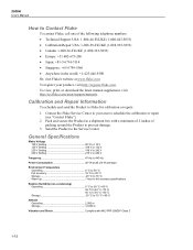
...• Japan: +81-3-6714-3114 • Singapore: +65-6799-5566 • Anywhere in the world: +1-425-446-5500 Or, visit Fluke's website at www.fluke.com. General Specifications Mains Voltage 100 V Setting 90 V to 110 V 120 V Setting 108 V to 132 V 220 V Setting 198 V to 242 V 240 V Setting ... Send the Product to the Service Center. Pack and secure the Product in your product, visit http://register.fluke.com. 2638A Users Manual How to Contact Fluke To contact Fluke, call one of packing around the Product to prevent damage. 3. To register your area to schedule the calibration...
...• Japan: +81-3-6714-3114 • Singapore: +65-6799-5566 • Anywhere in the world: +1-425-446-5500 Or, visit Fluke's website at www.fluke.com. General Specifications Mains Voltage 100 V Setting 90 V to 110 V 120 V Setting 108 V to 132 V 220 V Setting 198 V to 242 V 240 V Setting ... Send the Product to the Service Center. Pack and secure the Product in your product, visit http://register.fluke.com. 2638A Users Manual How to Contact Fluke To contact Fluke, call one of packing around the Product to prevent damage. 3. To register your area to schedule the calibration...

User Manual
Page 23
... Device Port Connector type Type B Class Instrument Function Control and data transfer Command protocol SCPI LAN Function Control and data transfer Network protocols Ethernet 10/100, TCP/IP Command protocol SCPI Dimensions Height 150 mm Width 245 mm Depth 385 mm Weight 6 kg (typical configuration) Shipping Weight 9.5 kg (typical configuration) Conformity...
... Device Port Connector type Type B Class Instrument Function Control and data transfer Command protocol SCPI LAN Function Control and data transfer Network protocols Ethernet 10/100, TCP/IP Command protocol SCPI Dimensions Height 150 mm Width 245 mm Depth 385 mm Weight 6 kg (typical configuration) Shipping Weight 9.5 kg (typical configuration) Conformity...

User Manual
Page 24
2638A Users Manual Measurement Specifications Accuracy specifications generally are relative to calibration standards and assume a controlled electromagnetic environment per channel) Display Resolution 4 ½ to 6 ½ digits, ...;V 10 μV 1 μV 10 MΩ or >10 GΩ [1] 10 V 10.00000 V 1 mV 100 μV 10 μV 10 MΩ or >10 GΩ [1] 100 V 100.0000 V 10 mV 1 mV 100 μV 10 MΩ ±1 % 300 V 300.000 V 100 mV 10 mV 1 mV 10 MΩ ±1 % [1] - The confidence level for accuracy specifications is 99 % within an environment temperature...
2638A Users Manual Measurement Specifications Accuracy specifications generally are relative to calibration standards and assume a controlled electromagnetic environment per channel) Display Resolution 4 ½ to 6 ½ digits, ...;V 10 μV 1 μV 10 MΩ or >10 GΩ [1] 10 V 10.00000 V 1 mV 100 μV 10 μV 10 MΩ or >10 GΩ [1] 100 V 100.0000 V 10 mV 1 mV 100 μV 10 MΩ ±1 % 300 V 300.000 V 100 mV 10 mV 1 mV 10 MΩ ±1 % [1] - The confidence level for accuracy specifications is 99 % within an environment temperature...

User Manual
Page 25
...+ 0.0001 % 0.0005 % + 0.0003 % DC Voltage Additional Errors Digits 6 ½ 6 ½ 6 ½ 5 ½ 4 ½ 4 ½ NPLC 200 100 10 (Slow) 1 (Medium) 0.2 (Fast) 0.02 Ch. 1 Product Overview and Specifications Measurement Specifications DC Voltage Accuracy Accuracy is given as ± (% measurement + % of range.... x20 add 2 μV add 2 μV add 2 μV add 2 μV - Range 100 mV 1 V 10 V 100 V 300 V 24 Hour (23 ±1 °C) 0.0025 % + 0.003 % 0.0018 % + 0.0006 % 0.0013 % + 0.0004 % 0.0018 % + 0.0006...
...+ 0.0001 % 0.0005 % + 0.0003 % DC Voltage Additional Errors Digits 6 ½ 6 ½ 6 ½ 5 ½ 4 ½ 4 ½ NPLC 200 100 10 (Slow) 1 (Medium) 0.2 (Fast) 0.02 Ch. 1 Product Overview and Specifications Measurement Specifications DC Voltage Accuracy Accuracy is given as ± (% measurement + % of range.... x20 add 2 μV add 2 μV add 2 μV add 2 μV - Range 100 mV 1 V 10 V 100 V 300 V 24 Hour (23 ±1 °C) 0.0025 % + 0.003 % 0.0018 % + 0.0006 % 0.0013 % + 0.0004 % 0.0018 % + 0.0006...

User Manual
Page 26
...;C 0.01 % + 0.005 % 0.01 % + 0.005 % 0.05 % + 0.01 % 0.01 % + 0.005 % 0.01 % + 0.005 % 0.05 % + 0.01 % 0.01 % + 0.005 % 0.01 % + 0.005 % 0.05 % + 0.01 % 0.01 % + 0.005 % 0.01 % + 0.005 % 0.05 % + 0.01 % 0.01 % + 0.005 % 0.01 % + 0.005 % 0.05 % + 0.03 % Additional Low Frequency Errors Error is given as % of range). 2638A Users Manual AC Voltage Input Characteristics Range 100 mV 1 V 10 V 100 V 300 V Resolution 100.0000 mV 1.000000 V 10...
...;C 0.01 % + 0.005 % 0.01 % + 0.005 % 0.05 % + 0.01 % 0.01 % + 0.005 % 0.01 % + 0.005 % 0.05 % + 0.01 % 0.01 % + 0.005 % 0.01 % + 0.005 % 0.05 % + 0.01 % 0.01 % + 0.005 % 0.01 % + 0.005 % 0.05 % + 0.01 % 0.01 % + 0.005 % 0.01 % + 0.005 % 0.05 % + 0.03 % Additional Low Frequency Errors Error is given as % of range). 2638A Users Manual AC Voltage Input Characteristics Range 100 mV 1 V 10 V 100 V 300 V Resolution 100.0000 mV 1.000000 V 10...

User Manual
Page 27
1 Product Overview and Specifications Measurement Specifications DC Current Input Protection 0.15 A / 600 V Resettable PTC DC Current Input Characteristics Range Resolution 100 μA 1 mA 10 mA 100 mA 100.0000 µA 1.000000 mA 10.00000 mA 100.0000 mA Fast 4½ Digits 10 nA 100 nA 1 μA 10 μA Resolution Medium 5 ½ Digits 1 nA 10 nA 100 nA 1 μA Slow 6 ½ Digits 0.1 nA 1 nA 10 nA 100 nA Reference Resistance (Ohms) 1k Ω 1k Ω 10 Ω 10 Ω Burden Voltage
1 Product Overview and Specifications Measurement Specifications DC Current Input Protection 0.15 A / 600 V Resettable PTC DC Current Input Characteristics Range Resolution 100 μA 1 mA 10 mA 100 mA 100.0000 µA 1.000000 mA 10.00000 mA 100.0000 mA Fast 4½ Digits 10 nA 100 nA 1 μA 10 μA Resolution Medium 5 ½ Digits 1 nA 10 nA 100 nA 1 μA Slow 6 ½ Digits 0.1 nA 1 nA 10 nA 100 nA Reference Resistance (Ohms) 1k Ω 1k Ω 10 Ω 10 Ω Burden Voltage

User Manual
Page 28
2638A Users Manual AC Current Input Characteristics Range Resolution 4 ½ Digits Resolution 5 ½ Digits 6 ½ Digits Reference Resistance Burden Voltage 100 μA 1 mA 10 mA 100 mA 100.0000 µA 1.000000 mA 10.00000 mA 100.0000 mA 10 nA 100 nA 1 μA 10 μA 1 nA 10 nA 100 nA 1 μA 0.1 nA 1 nA 10 nA 100 nA 1 kΩ 1 kΩ 10 Ω 10 Ω
2638A Users Manual AC Current Input Characteristics Range Resolution 4 ½ Digits Resolution 5 ½ Digits 6 ½ Digits Reference Resistance Burden Voltage 100 μA 1 mA 10 mA 100 mA 100.0000 µA 1.000000 mA 10.00000 mA 100.0000 mA 10 nA 100 nA 1 μA 10 μA 1 nA 10 nA 100 nA 1 μA 0.1 nA 1 nA 10 nA 100 nA 1 kΩ 1 kΩ 10 Ω 10 Ω

User Manual
Page 29
... % 0.04 % + 0.002 % 0.8 % + 0.01 % T.C./ °C Outside 18 °C to LO input. Lead Resistance (4-wire ohms 10 Ω per lead for 100 Ω, 1 kΩ ranges. 1 kΩ per lead on all other ranges. Basic accuracy specification is given as ± (% measurement + % of range + 17 mΩ...% + 0.0001 % 0.0006 % + 0.0001 % 0.0006 % + 0.0001 % 0.001 % + 0.0002 % 0.003 % + 0.0004 % 0.05 % + 0.002 % Digits 6 ½ 6 ½ 6 ½ 5 ½ 4 ½ 4 ½ NPLC 200 100 10 (Slow) 1 (Medium) 0.2 (Fast)(only for 2-wire) 0.02 (only for 2-wire) Additional NPLC Noise Error 0 % of range 0 % ...
... % 0.04 % + 0.002 % 0.8 % + 0.01 % T.C./ °C Outside 18 °C to LO input. Lead Resistance (4-wire ohms 10 Ω per lead for 100 Ω, 1 kΩ ranges. 1 kΩ per lead on all other ranges. Basic accuracy specification is given as ± (% measurement + % of range + 17 mΩ...% + 0.0001 % 0.0006 % + 0.0001 % 0.0006 % + 0.0001 % 0.001 % + 0.0002 % 0.003 % + 0.0004 % 0.05 % + 0.002 % Digits 6 ½ 6 ½ 6 ½ 5 ½ 4 ½ 4 ½ NPLC 200 100 10 (Slow) 1 (Medium) 0.2 (Fast)(only for 2-wire) 0.02 (only for 2-wire) Additional NPLC Noise Error 0 % of range 0 % ...

User Manual
Page 30
... Rate Slow 10 PLC Medium 2 PLC Fast 1 PLC RTD Temperature Accuracy Accuracy is for 4-wire 100 Ω nominal RTD, using the slow sample rate. When using channels x01 through x20, and add external lead wire resistance mismatch. 2638A Users Manual RTD Temperature Range 200 °C to 1200 °C (depending on the sensor...
... Rate Slow 10 PLC Medium 2 PLC Fast 1 PLC RTD Temperature Accuracy Accuracy is for 4-wire 100 Ω nominal RTD, using the slow sample rate. When using channels x01 through x20, and add external lead wire resistance mismatch. 2638A Users Manual RTD Temperature Range 200 °C to 1200 °C (depending on the sensor...

User Manual
Page 31
With 2-wire thermistor add the number given in the table to the accuracy specification for a 4-wire thermistor using fast sample rate (NPLC When using medium or slow sample rate. 1 Product Overview and Specifications Measurement Specifications Thermistor Temperature Accuracy Accuracy specifications are for internal resistance.
With 2-wire thermistor add the number given in the table to the accuracy specification for a 4-wire thermistor using fast sample rate (NPLC When using medium or slow sample rate. 1 Product Overview and Specifications Measurement Specifications Thermistor Temperature Accuracy Accuracy specifications are for internal resistance.

User Manual
Page 33
1 Product Overview and Specifications 2638A-100 Universal Input Module Thermocouple Measurement Characteristics Range -270 °C to 2315 °C Temperature Display Resolution Slow Sample Rate 0.01 °C Medium/Fast Sample Rate 0.1 °C Digital I/O Absolute Voltage Range 4 V to 30 V Input Minimum Logic High 2.0 V Input Maximum Logic Low 0.7 V Output Type open drain active low Output Logic Low (
1 Product Overview and Specifications 2638A-100 Universal Input Module Thermocouple Measurement Characteristics Range -270 °C to 2315 °C Temperature Display Resolution Slow Sample Rate 0.01 °C Medium/Fast Sample Rate 0.1 °C Digital I/O Absolute Voltage Range 4 V to 30 V Input Minimum Logic High 2.0 V Input Maximum Logic Low 0.7 V Output Type open drain active low Output Logic Low (

User Manual
Page 37
... with a voltage selector that must be set for first time use before mains power is connected. 1 2 Figure 2-1. Table 2-1. See Table 2-1. Fuses Voltage Selector Fuse Fluke Part Number 100 V 120 V 220 V 240 V 0.25 A, 250 V (slow blow) 0.25 A, 250 V (slow blow) 0.125 A, 250 V (slow blow) 0.125 A, 250 V (slow blow) 166306 166306 166488 166488 ... connected. 2 Initial Setup and Configuration Introduction Introduction This chapter supplies information and instructions on how to change the fuse. The selector can be set to 100 V, 120 V, 220 V, or 240 V.
... with a voltage selector that must be set for first time use before mains power is connected. 1 2 Figure 2-1. Table 2-1. See Table 2-1. Fuses Voltage Selector Fuse Fluke Part Number 100 V 120 V 220 V 240 V 0.25 A, 250 V (slow blow) 0.25 A, 250 V (slow blow) 0.125 A, 250 V (slow blow) 0.125 A, 250 V (slow blow) 166306 166306 166488 166488 ... connected. 2 Initial Setup and Configuration Introduction Introduction This chapter supplies information and instructions on how to change the fuse. The selector can be set to 100 V, 120 V, 220 V, or 240 V.

User Manual
Page 38
2638A Users Manual Connect to Mains Power Use the mains power cord to connect the Product to a 100 V ac, 120 V ac, or 230 V ac nominal outlet as shown in Figure 2-2. Warning To prevent possible electrical shock, fire, or personal injury: • ...
2638A Users Manual Connect to Mains Power Use the mains power cord to connect the Product to a 100 V ac, 120 V ac, or 230 V ac nominal outlet as shown in Figure 2-2. Warning To prevent possible electrical shock, fire, or personal injury: • ...

User Manual
Page 49
... through ChX20 by the use of various types to the Input Module then configure the associated channel. Input Wiring The Universal Input Module The 2686A-100 Universal Input Module (the Input Module) is used to wire inputs of an external shunt resistor. 3 Input and Channel Configuration Introduction Introduction This chapter supplies...
... through ChX20 by the use of various types to the Input Module then configure the associated channel. Input Wiring The Universal Input Module The 2686A-100 Universal Input Module (the Input Module) is used to wire inputs of an external shunt resistor. 3 Input and Channel Configuration Introduction Introduction This chapter supplies...

User Manual
Page 53
Other analog channels are 150 V max. [3] − 100 MΩ is for Ch001 only. 3 Input and Channel Configuration Input Wiring Table 3-1. Types of Inputs Type of Input Range and Types Channel Configuration Reference ac ...and dc Voltage Range: 0 V to 300 V [2] Page 3-18 ac and dc Current [1] Resistance (Ω) Platinum Resistance Thermometer (PRT) Range: 0 mA to ±100 mA 2-Wire or 4-Wire [3] Range: 0 Ω to 100 MΩ 2-Wire, 3-Wire or 4-Wire Types: • PT385 or PT392 • R0: 0.09 Ω to 1.2 kΩ Page 3-18 Page 3-19 Page...
Other analog channels are 150 V max. [3] − 100 MΩ is for Ch001 only. 3 Input and Channel Configuration Input Wiring Table 3-1. Types of Inputs Type of Input Range and Types Channel Configuration Reference ac ...and dc Voltage Range: 0 V to 300 V [2] Page 3-18 ac and dc Current [1] Resistance (Ω) Platinum Resistance Thermometer (PRT) Range: 0 mA to ±100 mA 2-Wire or 4-Wire [3] Range: 0 Ω to 100 MΩ 2-Wire, 3-Wire or 4-Wire Types: • PT385 or PT392 • R0: 0.09 Ω to 1.2 kΩ Page 3-18 Page 3-19 Page...

User Manual
Page 64
... the channel (optional). Set an alarm for all measurements. To expand the functionality of the Product, current sources can be connected to : Auto, 100 mV, 1 V, 10 V, 100 V, or 150 V. For voltage, set the voltage range to ChX01 through ChX20 by the use of an accessory shunt resistor. Current and Voltage Channels... this channel (optional). For current, set to configure an ac or dc voltage or current channel. Ch001 can be set the current range to: Auto, 100 μA, 1 mA, 10mA, or 100 mA. Input a custom alpha-numeric label to the measurement (optional...
... the channel (optional). Set an alarm for all measurements. To expand the functionality of the Product, current sources can be connected to : Auto, 100 mV, 1 V, 10 V, 100 V, or 150 V. For voltage, set the voltage range to ChX01 through ChX20 by the use of an accessory shunt resistor. Current and Voltage Channels... this channel (optional). For current, set to configure an ac or dc voltage or current channel. Ch001 can be set the current range to: Auto, 100 μA, 1 mA, 10mA, or 100 mA. Input a custom alpha-numeric label to the measurement (optional...

User Manual
Page 65
See "Sense Input Configuration" on page 3-5. Set the range to the measurement (optional). Ch001 can be set to 100 MΩ. Input a custom alpha-numeric label to configure a resistance channel. See "HI and LO Channel Alarms" on page 3-30. 3-19 3 Input and Channel Configuration ... Resistance function selection. Set up the channel for this channel (optional). See "Mx+B Scaling" on page 3-31. Apply Mx+B scaling to : Auto, 100 Ω, 1 kΩ, 10 kΩ, 100 kΩ, 1 MΩ or 10 MΩ. Table 3-5.
See "Sense Input Configuration" on page 3-5. Set the range to the measurement (optional). Ch001 can be set to 100 MΩ. Input a custom alpha-numeric label to configure a resistance channel. See "HI and LO Channel Alarms" on page 3-30. 3-19 3 Input and Channel Configuration ... Resistance function selection. Set up the channel for this channel (optional). See "Mx+B Scaling" on page 3-31. Apply Mx+B scaling to : Auto, 100 Ω, 1 kΩ, 10 kΩ, 100 kΩ, 1 MΩ or 10 MΩ. Table 3-5.