
Product Manual
Page 2
Parts, product repairs, and services are warranted for Fluke products online at Fluke's option, to refund of the purchase price, free of charge repair, or replacement of repair costs and obtain authorization before commencing the work. Fluke authorized resellers shall extend this warranty on new and unused products to end-user customers only but have no risk for damage in Fluke's opinion, has been misused, altered, neglected...
Parts, product repairs, and services are warranted for Fluke products online at Fluke's option, to refund of the purchase price, free of charge repair, or replacement of repair costs and obtain authorization before commencing the work. Fluke authorized resellers shall extend this warranty on new and unused products to end-user customers only but have no risk for damage in Fluke's opinion, has been misused, altered, neglected...

Product Manual
Page 3
... Front Panel Decal 7 Charging the PDA Battery 9 Installing the Software 9 Installing Power View on the PDA 9 Language Selection 10 PC System Requirement for Power Analyze 10 Installing Power Analyze 10 Installing the Power Recorder at a Facility 11 Work Flow...11 Installing the Recorder 11 Connecting the Recorder to the Wiring 12 Verifying Your Connection 13 Finishing Up 13 Managing Recorded Data 14 Power Type Diagrams 14 Communicating with the Recorder Using Power View 25 Navigating in Power View...
... Front Panel Decal 7 Charging the PDA Battery 9 Installing the Software 9 Installing Power View on the PDA 9 Language Selection 10 PC System Requirement for Power Analyze 10 Installing Power Analyze 10 Installing the Power Recorder at a Facility 11 Work Flow...11 Installing the Recorder 11 Connecting the Recorder to the Wiring 12 Verifying Your Connection 13 Finishing Up 13 Managing Recorded Data 14 Power Type Diagrams 14 Communicating with the Recorder Using Power View 25 Navigating in Power View...

Product Manual
Page 4
1750 Operators Manual Trend Screen 38 Viewing Phases 38 Setting Up the Recorder 39 Setting the Clock 40 Probe Detect 40 Setting the IP Address 41 Adding a Measurement Description 41 Configure Nominal Power Values 42 Using Phase Swap 42 Setting the Volts and Current Ratio 43 Assign Recorder Name and Password 43 Setting the Snapshot Period - Periodic Waveform Capture Setting 44 Change Display Language and Phase Identifier 45...
1750 Operators Manual Trend Screen 38 Viewing Phases 38 Setting Up the Recorder 39 Setting the Clock 40 Probe Detect 40 Setting the IP Address 41 Adding a Measurement Description 41 Configure Nominal Power Values 42 Using Phase Swap 42 Setting the Volts and Current Ratio 43 Assign Recorder Name and Password 43 Setting the Snapshot Period - Periodic Waveform Capture Setting 44 Change Display Language and Phase Identifier 45...
Product Manual
Page 7
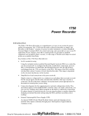
... Fluke. The Recorder then configures its measurement system appropriately for the supported power network configurations (delta, Wye, and others) appear on each phase that you can swap the phase to another channel by changing an internal Recorder setting using . • Connection diagrams for the model of probe is a comprehensive yet easy to confirm the connections. Once you make connections, you want to use system for control and setup, and a powerful...
... Fluke. The Recorder then configures its measurement system appropriately for the supported power network configurations (delta, Wye, and others) appear on each phase that you can swap the phase to another channel by changing an internal Recorder setting using . • Connection diagrams for the model of probe is a comprehensive yet easy to confirm the connections. Once you make connections, you want to use system for control and setup, and a powerful...

Product Manual
Page 8
... explosive gas, vapor, or in this manual. XW Warning To prevent possible electrical shock, fire, or personal injury: • Carefully read all instructions. • Do not work alone. • Do not use the Product around the terminals. • Remove all probes, test leads, and accessories that are no user-replaceable parts in the mains power cord is connected to a protective earth ground. Hazardous voltage...
... explosive gas, vapor, or in this manual. XW Warning To prevent possible electrical shock, fire, or personal injury: • Carefully read all instructions. • Do not work alone. • Do not use the Product around the terminals. • Remove all probes, test leads, and accessories that are no user-replaceable parts in the mains power cord is connected to a protective earth ground. Hazardous voltage...

Product Manual
Page 9
...) Memory Card for downloading data Model 3140R, 400 A Clamps (4-not included with Basic version) AC power cord, 3 meters Personal Digital Assistant (PDA) with Wheels 4 MyFlukeStore Shop for Fluke products online at: www. .com 1.888.610.7664 Looped Lockable • 4003 RPM, Shipping Caddy with USB cable and accessories CD-ROM Manuals and Software 1750 Getting Started Guide Sheet of Front Panel Decals Sets of European Union and...
...) Memory Card for downloading data Model 3140R, 400 A Clamps (4-not included with Basic version) AC power cord, 3 meters Personal Digital Assistant (PDA) with Wheels 4 MyFlukeStore Shop for Fluke products online at: www. .com 1.888.610.7664 Looped Lockable • 4003 RPM, Shipping Caddy with USB cable and accessories CD-ROM Manuals and Software 1750 Getting Started Guide Sheet of Front Panel Decals Sets of European Union and...
Product Manual
Page 10
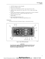
... • 4005 RPM, Shipping Container, Reusable • Replacement Voltage Lead Set • Clamp-on Current Transformers (i5s-PR 5 Amp, Clamp with 10 ft. Fluke 1750 Power Recorder 7 azd09f.eps WCaution Connecting the supplemental ground terminal and the line cord safety ground to different ground potentials creates a ground loop that can damage the Recorder. 5 MyFlukeStore Shop for Fluke products online at: www. .com 1.888.610.7664...
... • 4005 RPM, Shipping Container, Reusable • Replacement Voltage Lead Set • Clamp-on Current Transformers (i5s-PR 5 Amp, Clamp with 10 ft. Fluke 1750 Power Recorder 7 azd09f.eps WCaution Connecting the supplemental ground terminal and the line cord safety ground to different ground potentials creates a ground loop that can damage the Recorder. 5 MyFlukeStore Shop for Fluke products online at: www. .com 1.888.610.7664...

Product Manual
Page 11
... insufficient to different ground potentials creates a ground loop that a safety ground connection does exist through the line power cord. E SD status indicator Blinking green Blinking orange Off Reading from the Recorder, insert in normal range >110 % of the PDA. This is used . A USB SD card reader may also be used to connect the Recorder to the PC via Ethernet is the recommended method of data. 1750 Operators Manual Table...
... insufficient to different ground potentials creates a ground loop that a safety ground connection does exist through the line power cord. E SD status indicator Blinking green Blinking orange Off Reading from the Recorder, insert in normal range >110 % of the PDA. This is used . A USB SD card reader may also be used to connect the Recorder to the PC via Ethernet is the recommended method of data. 1750 Operators Manual Table...

Product Manual
Page 14
... version number shipped on the PDA. 8. Connect the PDA to your PDA user's guide for Fluke products online at: www. .com 1.888.610.7664 Keep your PDA. Refer to the PDA Users Manual for the installation. 6. Power Recorder Charging the PDA Battery Charging the PDA Battery Your PDA is similar to performing a hard reset. WCaution Do not leave important data on -screen instructions to install the ActiveSync software for Windows...
... version number shipped on the PDA. 8. Connect the PDA to your PDA user's guide for Fluke products online at: www. .com 1.888.610.7664 Keep your PDA. Refer to the PDA Users Manual for the installation. 6. Power Recorder Charging the PDA Battery Charging the PDA Battery Your PDA is similar to performing a hard reset. WCaution Do not leave important data on -screen instructions to install the ActiveSync software for Windows...

Product Manual
Page 16
... menu Settings>Language. 4. If the window does not automatically appear: a. on your new data). Select a language preference for Fluke products online at: www. .com 1.888.610.7664 Annotations are three distinct stages for a recording session. • Setup Setup, hookup, and verification of recording session You can change any way. Start Power Analyze on the CD. This is when you need to...
... menu Settings>Language. 4. If the window does not automatically appear: a. on your new data). Select a language preference for Fluke products online at: www. .com 1.888.610.7664 Annotations are three distinct stages for a recording session. • Setup Setup, hookup, and verification of recording session You can change any way. Start Power Analyze on the CD. This is when you need to...

Product Manual
Page 17
...; Connect the power cord to the Recorder using either the Setup Password menu in the Password text box and click OK. (Password protection is sufficient voltage and current. 5. After a minute, or two, all LEDs should flash ON, then OFF, and then each should not be oriented vertically or horizontally. 3. If a Recorder is within range and is within 2 m (6 ft) of the monitoring location. 2. 1750 Operators Manual Installing...
...; Connect the power cord to the Recorder using either the Setup Password menu in the Password text box and click OK. (Password protection is sufficient voltage and current. 5. After a minute, or two, all LEDs should flash ON, then OFF, and then each should not be oriented vertically or horizontally. 3. If a Recorder is within range and is within 2 m (6 ft) of the monitoring location. 2. 1750 Operators Manual Installing...

Product Manual
Page 18
... connection. Make sure the nominal voltage, nominal line frequency, and power type (delta, wye, other) are paired correctly, Phase A (L1) voltage to the correct phases, neutral and ground. 6. It is a good practice to insert a Start Mark when you are using Power View if they exist on the primary side of the same color should point toward the load. • Use the color-coding...
... connection. Make sure the nominal voltage, nominal line frequency, and power type (delta, wye, other) are paired correctly, Phase A (L1) voltage to the correct phases, neutral and ground. 6. It is a good practice to insert a Start Mark when you are using Power View if they exist on the primary side of the same color should point toward the load. • Use the color-coding...

Product Manual
Page 19
..., it using the Ethernet cable is not removed from the Recorder. Power type diagrams are also included on an internal non-physically accessible flash memory circuit. This can be done at : www. .com 1.888.610.7664 Downloading to Menu >Tools >1750 Internal Memory or Menu >Tools >1750 SD Memory. 1750 Operators Manual descriptions such as an aid in making the correct test lead connections.
..., it using the Ethernet cable is not removed from the Recorder. Power type diagrams are also included on an internal non-physically accessible flash memory circuit. This can be done at : www. .com 1.888.610.7664 Downloading to Menu >Tools >1750 Internal Memory or Menu >Tools >1750 SD Memory. 1750 Operators Manual descriptions such as an aid in making the correct test lead connections.
Product Manual
Page 30
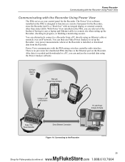
... the Ethernet port on the PDA, you are relieved of the burden of having to carry a laptop and Ethernet cable to a remote site when setting up the Recorder, view power measurements wherever the Recorder is recorded and downloaded to a Recorder from the Recorder. With Power View installed on the Recorder. Power View communicates with Power Analyze Software Fluke 1750 Power Recorder Direct Ethernet Connection Figure 14. After data is installed, or download data...
... the Ethernet port on the PDA, you are relieved of the burden of having to carry a laptop and Ethernet cable to a remote site when setting up the Recorder, view power measurements wherever the Recorder is recorded and downloaded to a Recorder from the Recorder. With Power View installed on the Recorder. Power View communicates with Power Analyze Software Fluke 1750 Power Recorder Direct Ethernet Connection Figure 14. After data is installed, or download data...
Product Manual
Page 31
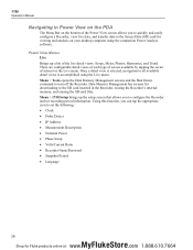
... the Shut Down command to all available detail views is accomplished using the companion Power Analyze software. Power View Menus Live Brings up the setup screen that allows you to quickly and easily configure a Recorder, view live detail views: Scope, Meter, Phasor, Harmonics, and Trend. Once a detail view is selected, navigation to turn off the Recorder. Menu > 1750 Setup brings up a list of the live data, and transfer data to...
... the Shut Down command to all available detail views is accomplished using the companion Power Analyze software. Power View Menus Live Brings up the setup screen that allows you to quickly and easily configure a Recorder, view live detail views: Scope, Meter, Phasor, Harmonics, and Trend. Once a detail view is selected, navigation to turn off the Recorder. Menu > 1750 Setup brings up a list of the live data, and transfer data to...

Product Manual
Page 36
... connected to set up password protection for a Recorder is inserted, the indicator flashes green for review using the Power Analyze software. If the SD status indicator flashes when the SD card has been inserted but it does not flash for Fluke products online at: www. .com 1.888.610.7664 Use a new card without a PDA or PC. Note A screen to the device. 2. Downloading Data and Erasing Memory Use...
... connected to set up password protection for a Recorder is inserted, the indicator flashes green for review using the Power Analyze software. If the SD status indicator flashes when the SD card has been inserted but it does not flash for Fluke products online at: www. .com 1.888.610.7664 Use a new card without a PDA or PC. Note A screen to the device. 2. Downloading Data and Erasing Memory Use...

Product Manual
Page 37
... were being connected, select the START mark annotation (if one was entered by the user) as nominal voltage or power type. To download ALL, tap the Write to view the Download screen. Green and red flags are file name annotations inserted during the recording session. The default settings of the screen show the start and stop times currently selected for the new download. Power View alerts you...
... were being connected, select the START mark annotation (if one was entered by the user) as nominal voltage or power type. To download ALL, tap the Write to view the Download screen. Green and red flags are file name annotations inserted during the recording session. The default settings of the screen show the start and stop times currently selected for the new download. Power View alerts you...

Product Manual
Page 47
... • Invert any current input clamp The screen shows check boxes to make a software-selectable correction without physically switching the cable. Current probes are AN, BN, CN, and NG. (N = neutral, G = ground). 1750 Operators Manual Configure Nominal Power Values This window contains the setup for Fluke products online at: www. .com 1.888.610.7664 It is available as an optional setting). If the power type is...
... • Invert any current input clamp The screen shows check boxes to make a software-selectable correction without physically switching the cable. Current probes are AN, BN, CN, and NG. (N = neutral, G = ground). 1750 Operators Manual Configure Nominal Power Values This window contains the setup for Fluke products online at: www. .com 1.888.610.7664 It is available as an optional setting). If the power type is...

Product Manual
Page 54
... number only signifies that interference will be determined by turning the equipment off and on, the user is encouraged to try to correct the interference by the size of Canada technical specifications were met. Power Requirements 100 to which case the user will not occur in a particular installation. Operation of the FCC Rules. Specifications for the System: Recorder and Power Analyze Software...
... number only signifies that interference will be determined by turning the equipment off and on, the user is encouraged to try to correct the interference by the size of Canada technical specifications were met. Power Requirements 100 to which case the user will not occur in a particular installation. Operation of the FCC Rules. Specifications for the System: Recorder and Power Analyze Software...

Product Manual
Page 56
Power Recorder Specifications for the System: Recorder and Power Analyze Software Transient Voltage (Impulse) Measurement Type Waveshape sampling, not peak detect Full Scale 8000 V pk Sample Resolution 200 nS Measurement Uncertainty 5 % reading ± 20 V (test parameters: 1000 V dc, 1000 V rms, 100 kHz) Dip (Sag) and Swell Measurements Voltage Swell (rms swell) Measurement Type True rms (one cycle calculation by overlapping each...
Power Recorder Specifications for the System: Recorder and Power Analyze Software Transient Voltage (Impulse) Measurement Type Waveshape sampling, not peak detect Full Scale 8000 V pk Sample Resolution 200 nS Measurement Uncertainty 5 % reading ± 20 V (test parameters: 1000 V dc, 1000 V rms, 100 kHz) Dip (Sag) and Swell Measurements Voltage Swell (rms swell) Measurement Type True rms (one cycle calculation by overlapping each...


