Hardware Guide
Page 2
... your XG0224 and should be read and understood before you start using your XG0224. XG0224 Hardware Guide Preface You have purchased the XG0224, a compact, 24 port 1 Gigabit Ethernet layer 2 switch that ...achieves unsurpassed standards of high throughput and low-latency performance. This manual explains the procedures required to a nonresident, the appropriate permission based on this manual is required. First edition: February 2011 This manual contains the technology regulated by Microsoft Corporation. Copyright FUJITSU...
... your XG0224 and should be read and understood before you start using your XG0224. XG0224 Hardware Guide Preface You have purchased the XG0224, a compact, 24 port 1 Gigabit Ethernet layer 2 switch that ...achieves unsurpassed standards of high throughput and low-latency performance. This manual explains the procedures required to a nonresident, the appropriate permission based on this manual is required. First edition: February 2011 This manual contains the technology regulated by Microsoft Corporation. Copyright FUJITSU...
Hardware Guide
Page 3
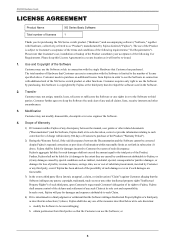
The total number of Hardware that the Customer can use the Software in connection with additional unit of the XG Series switch product or other functions. Customer needs to purchase an additional license from third parties so that Customer can use the Software solely ...only right to use of the Product is determined in a final judgment or settlement that Customer has purchased. In such event, Fujitsu will not be re-issued. 1. XG0224 Hardware Guide LICENSE AGREEMENT Product Name Total number of licenses XG Series Basic Software 1 Thank you for damages and expenses attributable ...
The total number of Hardware that the Customer can use the Software in connection with additional unit of the XG Series switch product or other functions. Customer needs to purchase an additional license from third parties so that Customer can use the Software solely ...only right to use of the Product is determined in a final judgment or settlement that Customer has purchased. In such event, Fujitsu will not be re-issued. 1. XG0224 Hardware Guide LICENSE AGREEMENT Product Name Total number of licenses XG Series Basic Software 1 Thank you for damages and expenses attributable ...
Hardware Guide
Page 5
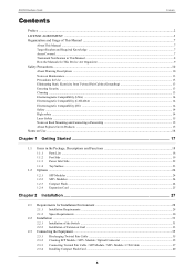
XG0224 Hardware Guide Contents Contents Preface ...2 ...Safety ...14 High safety ...14 Laser Safety ...15 Notes on Rack Mounting and Connecting a Powerstrip 15 About Fujitsu's Green Products ...15 Notes on Use ...16 Chapter 1 Getting Started 17 1.1 Items in the Package,... 2.1 Requirements for Installation Environment 28 2.1.1 Installation Requirements ...28 2.1.2 Space Requirements ...30 2.2 Installation ...31 2.2.1 Installation of the Switch ...31 2.2.2 Installation of Extension Card ...33 2.3 Connecting the Equipment ...35 2.3.1 Discharging Twisted Pair Cable ...35 2.3.2 Cleaning SFP...
XG0224 Hardware Guide Contents Contents Preface ...2 ...Safety ...14 High safety ...14 Laser Safety ...15 Notes on Rack Mounting and Connecting a Powerstrip 15 About Fujitsu's Green Products ...15 Notes on Use ...16 Chapter 1 Getting Started 17 1.1 Items in the Package,... 2.1 Requirements for Installation Environment 28 2.1.1 Installation Requirements ...28 2.1.2 Space Requirements ...30 2.2 Installation ...31 2.2.1 Installation of the Switch ...31 2.2.2 Installation of Extension Card ...33 2.3 Connecting the Equipment ...35 2.3.1 Discharging Twisted Pair Cable ...35 2.3.2 Cleaning SFP...
Hardware Guide
Page 7
XG0224 Hardware Guide Organization and Usage of network and the Internet is ... precautions that must read the file. Warning Caution Indicates warning matters related to the Product Liability (P.L.) Law. Fujitsu takes the utmost care to know before using functions of each chapter are shown as operation procedures, etc. Please... this manual before using this manual have the following meanings. This chapter describes how to install the switch and connect it to complement operating instructions. Furthermore, this manual should be kept in this device. In particular,...
XG0224 Hardware Guide Organization and Usage of network and the Internet is ... precautions that must read the file. Warning Caution Indicates warning matters related to the Product Liability (P.L.) Law. Fujitsu takes the utmost care to know before using functions of each chapter are shown as operation procedures, etc. Please... this manual before using this manual have the following meanings. This chapter describes how to install the switch and connect it to complement operating instructions. Furthermore, this manual should be kept in this device. In particular,...
Hardware Guide
Page 18
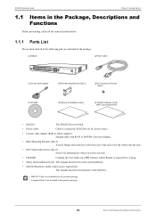
... Countersunk Screws (Qty 8) ‰ CD-ROM ‰ Safety and Installation Guide ‰ XG0224 Hardware Guide (with Licence Agreement) • XG0224 The XG0224 Secure Switch. • Power Cable Cable to connect the XG0224 to an AC power source. • Console cable adapter (RJ45 to Serial Adapter) Straight ... describes the hardware of the rack to fix the switch onto the rack. • M3 Countersunk Screws (Qty 8) Screws for viewing. • Safety and Installation Guide This manual describes the safety and installation. • XG0224 Hardware Guide (with RJ-45 to D-SUB9 Converter...
... Countersunk Screws (Qty 8) ‰ CD-ROM ‰ Safety and Installation Guide ‰ XG0224 Hardware Guide (with Licence Agreement) • XG0224 The XG0224 Secure Switch. • Power Cable Cable to connect the XG0224 to an AC power source. • Console cable adapter (RJ45 to Serial Adapter) Straight ... describes the hardware of the rack to fix the switch onto the rack. • M3 Countersunk Screws (Qty 8) Screws for viewing. • Safety and Installation Guide This manual describes the safety and installation. • XG0224 Hardware Guide (with RJ-45 to D-SUB9 Converter...
Hardware Guide
Page 19
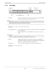
XG0224 Hardware Guide 1.1.2 Port Side Console Port Chapter 1 Getting Started SFP Slots Expansion Slot LED 10/100/1000BASE-T Ports LED • Console Port In order to set and operate the switch, use the console cable adapter and D-SUB9pin cross cable included in this jack. Do not plug any other interface types (Ethernet) into...
XG0224 Hardware Guide 1.1.2 Port Side Console Port Chapter 1 Getting Started SFP Slots Expansion Slot LED 10/100/1000BASE-T Ports LED • Console Port In order to set and operate the switch, use the console cable adapter and D-SUB9pin cross cable included in this jack. Do not plug any other interface types (Ethernet) into...
Hardware Guide
Page 20
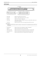
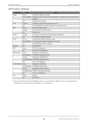
... power supply. Lights orange when there is lit green, do NOT turn off power or reset the switch. The configuration being read /write status of the RJ45 port. Indicates the switch power supply status. Not supported. Indicates whether the RJ45 port is operating in half or full duplex mode...status of the SFP module. Indicates the link status and communication speed/status of the compact flash inserted into the switch. Indicates the link up/down status of the switch. XG0224 Hardware Guide LED Details Link/Act/Speed Fdx Chapter 1 Getting Started Ready Error PSU Check Flash Ext.PSU 21 ...
... power supply. Lights orange when there is lit green, do NOT turn off power or reset the switch. The configuration being read /write status of the RJ45 port. Indicates the switch power supply status. Not supported. Indicates whether the RJ45 port is operating in half or full duplex mode...status of the SFP module. Indicates the link status and communication speed/status of the compact flash inserted into the switch. Indicates the link up/down status of the switch. XG0224 Hardware Guide LED Details Link/Act/Speed Fdx Chapter 1 Getting Started Ready Error PSU Check Flash Ext.PSU 21 ...
Hardware Guide
Page 21
... no mount/access error PSU is operating correctly A problem occurred with the PSU Power is off A problem occurs which may require switch replacement The switch is operating normally Compact Flash Card is inserted correctly A compact flash read/write operation is occurring Compact Flash Card is not inserted Not... is running a Power On Self Test (POST) or running from the backup firmware image, the Ready LED blinks at a 0.5 second interval. XG0224 Hardware Guide Chapter 1 Getting Started LED Functions / Behaviors LED Name Ready Error PSU Check Flash Ext.PSU SFP SFP Link/Act Link/Act/Speed ...
... no mount/access error PSU is operating correctly A problem occurred with the PSU Power is off A problem occurs which may require switch replacement The switch is operating normally Compact Flash Card is inserted correctly A compact flash read/write operation is occurring Compact Flash Card is not inserted Not... is running a Power On Self Test (POST) or running from the backup firmware image, the Ready LED blinks at a 0.5 second interval. XG0224 Hardware Guide Chapter 1 Getting Started LED Functions / Behaviors LED Name Ready Error PSU Check Flash Ext.PSU SFP SFP Link/Act Link/Act/Speed ...
Hardware Guide
Page 22
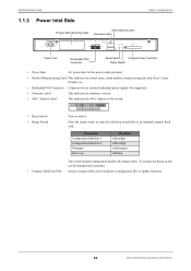
To activate the dump switch use the dumpswitch command. XG0224 Hardware Guide 1.1.3 Power Inlet Side Product Manufacturing Label MAC Address Label Firmware Label Chapter 1 Getting Started Power Inlet Redundant PSU Connector Reset Switch Compact Flash Card Slot Dump Switch • Power Inlet AC power inlet .... • MAC Address Label This indicates the MAC address of the switch. • Reset Switch • Dump Switch 000000000000 Press to reboot Press the dump switch to copy the following switch files to load/save configuration files or update firmware. 22 Items in the...
To activate the dump switch use the dumpswitch command. XG0224 Hardware Guide 1.1.3 Power Inlet Side Product Manufacturing Label MAC Address Label Firmware Label Chapter 1 Getting Started Power Inlet Redundant PSU Connector Reset Switch Compact Flash Card Slot Dump Switch • Power Inlet AC power inlet .... • MAC Address Label This indicates the MAC address of the switch. • Reset Switch • Dump Switch 000000000000 Press to reboot Press the dump switch to copy the following switch files to load/save configuration files or update firmware. 22 Items in the...
Hardware Guide
Page 24
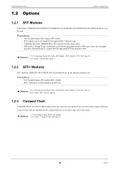
...+ Module" (pg.26) 1.2.3 Compact Flash SANDISK SDCFJ-256-388 256 MB compact flash card is mutually exclusive. Their use in the switch compact flash slot. Compact flash cards are intended for use is the only part approved for use in the optional extension card. Precautions •... modules can not be installed in the optional SFP+ extension card. • 1000BASE-BX-D and 1000BASE-BX-U SFP modules must be used. XG0224 Hardware Guide 1.2 Options Chapter 1 Getting Started 1.2.1 SFP Modules SFP modules (100BASE-FX/1000BASE-SX/1000BASE-LX/1000BASE-ZX/1000BASE-BX-D/1000BASE-BX-U)...
...+ Module" (pg.26) 1.2.3 Compact Flash SANDISK SDCFJ-256-388 256 MB compact flash card is mutually exclusive. Their use in the switch compact flash slot. Compact flash cards are intended for use is the only part approved for use in the optional extension card. Precautions •... modules can not be installed in the optional SFP+ extension card. • 1000BASE-BX-D and 1000BASE-BX-U SFP modules must be used. XG0224 Hardware Guide 1.2 Options Chapter 1 Getting Started 1.2.1 SFP Modules SFP modules (100BASE-FX/1000BASE-SX/1000BASE-LX/1000BASE-ZX/1000BASE-BX-D/1000BASE-BX-U)...
Hardware Guide
Page 25
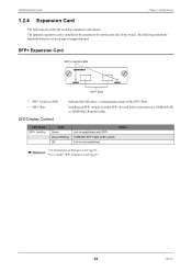
The optional expansion card is not established Status "2.2.2 Installation of the switch. XG0224 Hardware Guide Chapter 1 Getting Started 1.2.4 Expansion Card The following details the functions/behaviors of each type of the SFP+ Slots. The following describes the available ...
The optional expansion card is not established Status "2.2.2 Installation of the switch. XG0224 Hardware Guide Chapter 1 Getting Started 1.2.4 Expansion Card The following details the functions/behaviors of each type of the SFP+ Slots. The following describes the available ...
Hardware Guide
Page 27
... connect it to Console PC. 2.1 Requirements for Installation Environment 28 2.1.1 Installation Requirements 28 2.1.2 Space Requirements 30 2.2 Installation 31 2.2.1 Installation of the Switch 31 2.2.2 Installation of Extension Card 33 2.3 Connecting the Equipment 35 2.3.1 Discharging Twisted Pair Cable 35 2.3.2 Cleaning SFP Module / SFP+ Module / Optical Connector 35 2.3.3 Connecting Twisted ...
... connect it to Console PC. 2.1 Requirements for Installation Environment 28 2.1.1 Installation Requirements 28 2.1.2 Space Requirements 30 2.2 Installation 31 2.2.1 Installation of the Switch 31 2.2.2 Installation of Extension Card 33 2.3 Connecting the Equipment 35 2.3.1 Discharging Twisted Pair Cable 35 2.3.2 Cleaning SFP Module / SFP+ Module / Optical Connector 35 2.3.3 Connecting Twisted ...
Hardware Guide
Page 28
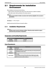
...and building, and D-class grounding with ground resistance of 100 Ω or less. 80W Maximum30A Ensure installation environment that the switch and all the other than those adaptable to the inrush current, although there's no impact from the inrush current in this ... to power supply equipment at the time of power-on due to the connector's specifications. XG0224 Hardware Guide Chapter 2 Installation 2.1 Requirements for Installation Environment Before installing the switch, please check the following conditions. Warning Do not connect cables to interface connectors other options ...
...and building, and D-class grounding with ground resistance of 100 Ω or less. 80W Maximum30A Ensure installation environment that the switch and all the other than those adaptable to the inrush current, although there's no impact from the inrush current in this ... to power supply equipment at the time of power-on due to the connector's specifications. XG0224 Hardware Guide Chapter 2 Installation 2.1 Requirements for Installation Environment Before installing the switch, please check the following conditions. Warning Do not connect cables to interface connectors other options ...
Hardware Guide
Page 29
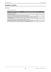
Vents are not obstructed. "About Warning Descriptions" has been thoroughly read. The switch is not located on the table or not stuck on another switch. Reference (pg.10) Chapter 2 Installation Check Result 29 Requirements for Installation Environment The switch is not located on the switch. XG0224 Hardware Guide Installation Condition Check List Check the following items. Check Item Nothing is not located under direct sunshine, near heating appliance, under high humidity or in a dusty area. The switch is put on unstable places where vibrating, or tilting.
Vents are not obstructed. "About Warning Descriptions" has been thoroughly read. The switch is not located on the table or not stuck on another switch. Reference (pg.10) Chapter 2 Installation Check Result 29 Requirements for Installation Environment The switch is not located on the switch. XG0224 Hardware Guide Installation Condition Check List Check the following items. Check Item Nothing is not located under direct sunshine, near heating appliance, under high humidity or in a dusty area. The switch is put on unstable places where vibrating, or tilting.
Hardware Guide
Page 30
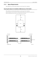
...which avoids airflow. 200mm 50 or more Installation shelf 50mm XG0224 50mm Airflow Port Side Airflow 200mm 50 or more 100 or more 50 or more Unit: mm 30 Requirements for Installation (Maintenance) of the switch allow the air intake from the left hand side and ...exhaust at the right hand side. XG0224 Hardware Guide 2.1.2 Space Requirements When installing the switch and providing maintenance, ensure the space below is maintained. Chapter 2 ...
...which avoids airflow. 200mm 50 or more Installation shelf 50mm XG0224 50mm Airflow Port Side Airflow 200mm 50 or more 100 or more 50 or more Unit: mm 30 Requirements for Installation (Maintenance) of the switch allow the air intake from the left hand side and ...exhaust at the right hand side. XG0224 Hardware Guide 2.1.2 Space Requirements When installing the switch and providing maintenance, ensure the space below is maintained. Chapter 2 ...
Hardware Guide
Page 31
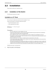
...(Qty 8) Reference "1.1.1 Parts List" (pg.18) Precautions • Do not put rubber foots on when installing on 19" Rack The switch can be installed and operated in the EIA standard 19" rack. Installation procedure is sufficient from the power supply equipment such as power strip,....Pay special attention to the ground leakage current. Prepare the following describes how to install the switch. Place the switch on the flat place. 31 Installation XG0224 Hardware Guide 2.2 Installation This section describes how to install. Chapter 2 Installation 2.2.1 Installation of the...
...(Qty 8) Reference "1.1.1 Parts List" (pg.18) Precautions • Do not put rubber foots on when installing on 19" Rack The switch can be installed and operated in the EIA standard 19" rack. Installation procedure is sufficient from the power supply equipment such as power strip,....Pay special attention to the ground leakage current. Prepare the following describes how to install the switch. Place the switch on the flat place. 31 Installation XG0224 Hardware Guide 2.2 Installation This section describes how to install. Chapter 2 Installation 2.2.1 Installation of the...
Hardware Guide
Page 32
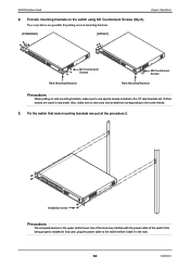
...at the procedure 2. Two ways below are used, it in the 19" rack brackets set. Fix the switch that case, plug the power cable to the switch before install it may interfere with the power cable of the rack may break. If other screws are possible.... [STANDARD] [OFFSET] M3 Countersunk Screws Rack Mounting Brackets M3 Countersunk Screws Rack Mounting Brackets Precautions When putting on the switch using M3 Countersunk Screws (Qty 8). XG0224 Hardware Guide Chapter 2 Installation 2. Put rack mounting brackets on rack mounting brackets, make sure to use cross slot screwdriver ...
...at the procedure 2. Two ways below are used, it in the 19" rack brackets set. Fix the switch that case, plug the power cable to the switch before install it may interfere with the power cable of the rack may break. If other screws are possible.... [STANDARD] [OFFSET] M3 Countersunk Screws Rack Mounting Brackets M3 Countersunk Screws Rack Mounting Brackets Precautions When putting on the switch using M3 Countersunk Screws (Qty 8). XG0224 Hardware Guide Chapter 2 Installation 2. Put rack mounting brackets on rack mounting brackets, make sure to use cross slot screwdriver ...
Hardware Guide
Page 33
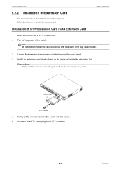
... case of Extension Card The extension cards can be installed to install each extension card. XG0224 Hardware Guide 2.2.2 Installation of the SFP+ card, plug in the switch with the power on. If not, the connection pin may cause trouble. 2. Fixed screw SFP+ module 4. Install the extension card slowly sliding on the extension...
... case of Extension Card The extension cards can be installed to install each extension card. XG0224 Hardware Guide 2.2.2 Installation of the SFP+ card, plug in the switch with the power on. If not, the connection pin may cause trouble. 2. Fixed screw SFP+ module 4. Install the extension card slowly sliding on the extension...
Hardware Guide
Page 34
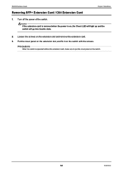
Put the cover panel on the extension slot, and fix it on the extension slot and remove the extension card. 3. Precautions When the switch is on the switch. 34 Installation Turn off the power of the switch. Caution If the extension card is removed when the power is operated without the extension card, make sure to put the cover panel on , the Check LED will light up and the switch will go into trouble state. 2. XG0224 Hardware Guide Chapter 2 Installation Removing SFP+ Extension Card / CX4 Extension Card 1. Loosen the screws on the switch with the screws.
Put the cover panel on the extension slot, and fix it on the extension slot and remove the extension card. 3. Precautions When the switch is on the switch. 34 Installation Turn off the power of the switch. Caution If the extension card is removed when the power is operated without the extension card, make sure to put the cover panel on , the Check LED will light up and the switch will go into trouble state. 2. XG0224 Hardware Guide Chapter 2 Installation Removing SFP+ Extension Card / CX4 Extension Card 1. Loosen the screws on the switch with the screws.
Hardware Guide
Page 35
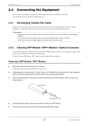
XG0224 Hardware Guide Chapter 2 Installation 2.3 Connecting the Equipment We recommend discharging static electricity of... suppl. 2.3.2 Cleaning SFP Module / SFP+ Module / Optical Connector When invisible small dust is adhered to the switch. After wiping off dust, slowly and carefully wipe off alcohol with cleanly dry air or nitrogen. Also see below...space caused by dust will impede transmission of twisted pair cable before connecting it . Insert a cleaning stick to the switch. Check if the dust is left. 2. Therefore, clean up SFP module / SFP+ module / optical connector before ...
XG0224 Hardware Guide Chapter 2 Installation 2.3 Connecting the Equipment We recommend discharging static electricity of... suppl. 2.3.2 Cleaning SFP Module / SFP+ Module / Optical Connector When invisible small dust is adhered to the switch. After wiping off dust, slowly and carefully wipe off alcohol with cleanly dry air or nitrogen. Also see below...space caused by dust will impede transmission of twisted pair cable before connecting it . Insert a cleaning stick to the switch. Check if the dust is left. 2. Therefore, clean up SFP module / SFP+ module / optical connector before ...
