Hardware Guide
Page 3
... can use the Software; Please keep the Software free and clear of license specified above , Fujitsu shall take any other intellectual property right ("Intellectual Property Rights") of such third party, upon Customer's request and Customer's delegation of its rights to Fujitsu, Fujitsu shall assume control of the defense and settlement of the XG Series switch product or other related documents ("Documentation") and the Software, Fujitsu...
... can use the Software; Please keep the Software free and clear of license specified above , Fujitsu shall take any other intellectual property right ("Intellectual Property Rights") of such third party, upon Customer's request and Customer's delegation of its rights to Fujitsu, Fujitsu shall assume control of the defense and settlement of the XG Series switch product or other related documents ("Documentation") and the Software, Fujitsu...
Hardware Guide
Page 5
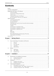
...on Rack Mounting and Connecting a Powerstrip 15 About Fujitsu's Green Products ...15 Notes on Use ...16 Chapter 1 Getting Started 17 1.1 Items in the Package, Descriptions and Functions 18 1.1.1 Parts List ...18 1.1.2 Port Side ...19 1.1.3 Power Inlet Side ...22 1.1.4 Top Surface ...22 1.1.5 Bottom Surface ...23 1.2 Options ...24 1.2.1 SFP Modules ...24 1.2.2 SFP+ Modules ...24 1.2.3 Expansion Card ...25 Chapter 2 Installation 27 2.1 Requirements for Installation Environment 28 2.1.1 Installation Requirements ...28 2.1.2 Space Requirements ...30 2.2 Installation ...31 2.2.1 Installation...
...on Rack Mounting and Connecting a Powerstrip 15 About Fujitsu's Green Products ...15 Notes on Use ...16 Chapter 1 Getting Started 17 1.1 Items in the Package, Descriptions and Functions 18 1.1.1 Parts List ...18 1.1.2 Port Side ...19 1.1.3 Power Inlet Side ...22 1.1.4 Top Surface ...22 1.1.5 Bottom Surface ...23 1.2 Options ...24 1.2.1 SFP Modules ...24 1.2.2 SFP+ Modules ...24 1.2.3 Expansion Card ...25 Chapter 2 Installation 27 2.1 Requirements for Installation Environment 28 2.1.1 Installation Requirements ...28 2.1.2 Space Requirements ...30 2.2 Installation ...31 2.2.1 Installation...

Hardware Guide
Page 7
... Titles Chapter 1 Getting Started Chapter 2 Installation Contents This chapter lists the items that our products can be taken when using this device. Reference Indicates related matters such as follows. In addition, the README file on CD-ROM contains important information. Read this manual thoroughly before using this device. This chapter describes how to install the switch and connect it to complement operating instructions. Note Indicates...
... Titles Chapter 1 Getting Started Chapter 2 Installation Contents This chapter lists the items that our products can be taken when using this device. Reference Indicates related matters such as follows. In addition, the README file on CD-ROM contains important information. Read this manual thoroughly before using this device. This chapter describes how to install the switch and connect it to complement operating instructions. Note Indicates...
Hardware Guide
Page 12
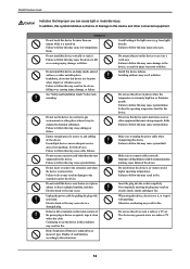
... extension card other unstable places. Failure to follow this may cause cable failures. Do not use this device indoors. XG0448 Hardware Guide Indicates that emits strong magnetic fields. Failure to follow this device near a radio or a TV set . 12 Failure to fall over , causing injury, damage, or failure. Installing outdoors may occur. Ensure enough space for more than the ones supported...
... extension card other unstable places. Failure to follow this may cause cable failures. Do not use this device indoors. XG0448 Hardware Guide Indicates that emits strong magnetic fields. Failure to follow this device near a radio or a TV set . 12 Failure to fall over , causing injury, damage, or failure. Installing outdoors may occur. Ensure enough space for more than the ones supported...
Hardware Guide
Page 13
... detergent to the XG0448 can cause the device or its partners accept no password is set a password. Connecting a statically charged twisted pair cable to dampen the cloth. Reference User's Guide "5.14 Password Information" (pg.257) Cleaning If cleaning the device while in the intended device. Before using the product, it should not repair this device. Use a static removal tool to discharge twisted pair cables to ground prior to connecting them to become...
... detergent to the XG0448 can cause the device or its partners accept no password is set a password. Connecting a statically charged twisted pair cable to dampen the cloth. Reference User's Guide "5.14 Password Information" (pg.257) Cleaning If cleaning the device while in the intended device. Before using the product, it should not repair this device. Use a static removal tool to discharge twisted pair cables to ground prior to connecting them to become...
Hardware Guide
Page 15
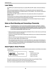
... module's port openings. The maximum current leakage for use in the XG0448 must only be used for the power strip are not connected, invisible laser light may occur through the ground line of the powerstrip. High rate of the device. Install the device not to obstruct the inlet and exhaust ventilation surfaces. • Make sure to check the maximum loading capacity of the rack to be mounted in a rack...
... module's port openings. The maximum current leakage for use in the XG0448 must only be used for the power strip are not connected, invisible laser light may occur through the ground line of the powerstrip. High rate of the device. Install the device not to obstruct the inlet and exhaust ventilation surfaces. • Make sure to check the maximum loading capacity of the rack to be mounted in a rack...
Hardware Guide
Page 16
... restore configurations in PDF format. Unless the configuration information is provided on Use Before using this device, please read the following. • Customers are still not available after the configuration is required for viewing the manual. 16 In this case, contact Fujitsu or Fujitsu's certified support engineer for further instruction. • Do not turn the power off or reset the system during a firmware update, or the device cannot be enabled. • A User's Guide...
... restore configurations in PDF format. Unless the configuration information is provided on Use Before using this device, please read the following. • Customers are still not available after the configuration is required for viewing the manual. 16 In this case, contact Fujitsu or Fujitsu's certified support engineer for further instruction. • Do not turn the power off or reset the system during a firmware update, or the device cannot be enabled. • A User's Guide...
Hardware Guide
Page 18
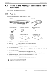
... 1 Getting Started 1.1 Items in the Package, Descriptions and Functions Before proceeding, check all the items described below. 1.1.1 Parts List Please check that all of the following parts are included in the package. ‰ XG0448 ‰ Power Cable ‰ Console cable adapter ‰ Rack Mounting Brackets (Qty 2) ‰ M3 Countersunk Screws (Qty 8) ‰ CD-ROM ‰ Safety and Installation Guid ‰ XG0448 Hardware Guide (with Licence Agreement) • XG0448 The XG0448 Secure Switch. • Power Cable Cable to connect...
... 1 Getting Started 1.1 Items in the Package, Descriptions and Functions Before proceeding, check all the items described below. 1.1.1 Parts List Please check that all of the following parts are included in the package. ‰ XG0448 ‰ Power Cable ‰ Console cable adapter ‰ Rack Mounting Brackets (Qty 2) ‰ M3 Countersunk Screws (Qty 8) ‰ CD-ROM ‰ Safety and Installation Guid ‰ XG0448 Hardware Guide (with Licence Agreement) • XG0448 The XG0448 Secure Switch. • Power Cable Cable to connect...
Hardware Guide
Page 19
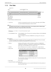
... Port LED 10/100/1000BASE-T Ports Chapter 1 Getting Started LED USB Port Dump Switch Reset Switch Product Part Number, Serial Number Label SFP Slots • Console Port In order to set and operate the switch, use the console cable adapter and D-SUB9pin cross cable included in this jack. Do not plug any other interface types (Ethernet) into this package to connect to an installed USB memory. Information Configuration Definition 1 Configuration Definition 2 Firmware Error Log File Name /um0/config1 /um0/config2 /um0/firmware /um0/elog The switch default configuration disables...
... Port LED 10/100/1000BASE-T Ports Chapter 1 Getting Started LED USB Port Dump Switch Reset Switch Product Part Number, Serial Number Label SFP Slots • Console Port In order to set and operate the switch, use the console cable adapter and D-SUB9pin cross cable included in this jack. Do not plug any other interface types (Ethernet) into this package to connect to an installed USB memory. Information Configuration Definition 1 Configuration Definition 2 Firmware Error Log File Name /um0/config1 /um0/config2 /um0/firmware /um0/elog The switch default configuration disables...
Hardware Guide
Page 20
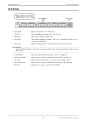
... switch. Not supported. Indicates the link up/down status of the switch. Indicates a USB memory mount/access error occurred. XG0448 Hardware Guide LED Details Ready Error PSU Check Flash Ext.PSU Link/Act/Speed Fdx Chapter 1 Getting Started SFP Link/Act SFP • Ready LED • Error LED • PSU LED • Check LED • Flash LED Indicates the operational state of the SFP module. 20 Items in half or full duplex mode. Lights orange when there is lit green, do NOT turn off power or reset the switch...
... switch. Not supported. Indicates the link up/down status of the switch. Indicates a USB memory mount/access error occurred. XG0448 Hardware Guide LED Details Ready Error PSU Check Flash Ext.PSU Link/Act/Speed Fdx Chapter 1 Getting Started SFP Link/Act SFP • Ready LED • Error LED • PSU LED • Check LED • Flash LED Indicates the operational state of the SFP module. 20 Items in half or full duplex mode. Lights orange when there is lit green, do NOT turn off power or reset the switch...
Hardware Guide
Page 21
... the backup firmware image (*) Off A problem has occurred Error Orange Indicates a compact flash mount/access error Off If a compact flash is installed, indicates no mount/access error PSU Green PSU is operating correctly Off Power is off Check Orange A problem occurs which may require switch replacement Orange Blinking Firmware in the Package, Descriptions and Functions XG0448 Hardware Guide Chapter 1 Getting Started LED Functions / Behaviors LED Name State Status Ready Green Switch has started up correctly Green Blinking Switch is running a Power On Self Test (POST...
... the backup firmware image (*) Off A problem has occurred Error Orange Indicates a compact flash mount/access error Off If a compact flash is installed, indicates no mount/access error PSU Green PSU is operating correctly Off Power is off Check Orange A problem occurs which may require switch replacement Orange Blinking Firmware in the Package, Descriptions and Functions XG0448 Hardware Guide Chapter 1 Getting Started LED Functions / Behaviors LED Name State Status Ready Green Switch has started up correctly Green Blinking Switch is running a Power On Self Test (POST...
Hardware Guide
Page 22
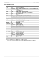
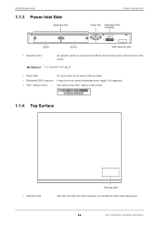
Reference "1.2.3 Expansion Card" (pg.25) • Power Inlet AC power inlet for the power cable provided. • Redundant PSU Connector Connector for an external redundant power supply. XG0448 Hardware Guide 1.1.3 Power Inlet Side Expansion Slot Chapter 1 Getting Started Power Inlet Redundant PSU Connector SLOT1 SLOT2 MAC Address Label • Expansion Slot An optional expansion card can be installed in the expansion slots on the port side of the switch. 000000000000 1.1.4 Top Surface...
Reference "1.2.3 Expansion Card" (pg.25) • Power Inlet AC power inlet for the power cable provided. • Redundant PSU Connector Connector for an external redundant power supply. XG0448 Hardware Guide 1.1.3 Power Inlet Side Expansion Slot Chapter 1 Getting Started Power Inlet Redundant PSU Connector SLOT1 SLOT2 MAC Address Label • Expansion Slot An optional expansion card can be installed in the expansion slots on the port side of the switch. 000000000000 1.1.4 Top Surface...
Hardware Guide
Page 25
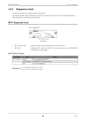
... traffic activity Link is installed in either SFP+ slot will allow connection to a 10GBASE-SR or 10GBASE-LR optical cable. SFP+ Expansion Card SFP+ Link/Act LEDs SFP+ Slots • SFP+ Link/Act LEDs • SFP+ Slots Indicated the link status/communication status of Extension Card" (pg.33) Reference User's Guide " SFP+ Expansion Card" (pg.27) 25 Options The following describes the available expansion card options. XG0448 Hardware Guide Chapter 1 Getting Started 1.2.3 Expansion Card The following details the functions/behaviors of each type...
... traffic activity Link is installed in either SFP+ slot will allow connection to a 10GBASE-SR or 10GBASE-LR optical cable. SFP+ Expansion Card SFP+ Link/Act LEDs SFP+ Slots • SFP+ Link/Act LEDs • SFP+ Slots Indicated the link status/communication status of Extension Card" (pg.33) Reference User's Guide " SFP+ Expansion Card" (pg.27) 25 Options The following describes the available expansion card options. XG0448 Hardware Guide Chapter 1 Getting Started 1.2.3 Expansion Card The following details the functions/behaviors of each type...

Hardware Guide
Page 27
... to Console PC. 2.1 Requirements for Installation Environment 28 2.1.1 Installation Requirements 28 2.1.2 Space Requirements 30 2.2 Installation 31 2.2.1 Installation of the Switch 31 2.2.2 Installation of Extension Card 33 2.3 Connecting the Equipment 35 2.3.1 Discharging Twisted Pair Cable 35 2.3.2 Cleaning SFP Module / SFP+ Module / Optical Connector 35 2.3.3 Connecting Twisted Pair Cable / SFP Module 37 2.3.4 Connecting Twisted Pair Cable / SFP+ Module / CX4 Cable 39 2.3.5 Plugging in the USB Memory 41 2.4 Connecting a Setup PC 42 2.5 Time Setting 45 2.6 Set up IP address 46
... to Console PC. 2.1 Requirements for Installation Environment 28 2.1.1 Installation Requirements 28 2.1.2 Space Requirements 30 2.2 Installation 31 2.2.1 Installation of the Switch 31 2.2.2 Installation of Extension Card 33 2.3 Connecting the Equipment 35 2.3.1 Discharging Twisted Pair Cable 35 2.3.2 Cleaning SFP Module / SFP+ Module / Optical Connector 35 2.3.3 Connecting Twisted Pair Cable / SFP Module 37 2.3.4 Connecting Twisted Pair Cable / SFP+ Module / CX4 Cable 39 2.3.5 Plugging in the USB Memory 41 2.4 Connecting a Setup PC 42 2.5 Time Setting 45 2.6 Set up IP address 46
Hardware Guide
Page 31
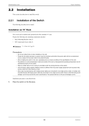
..., service outlet from other devices or rack. • When rack mounted devices with multiple power cables are connected to one single service outlet, or multiple rack mounted devices with single power cable are connected to a place near the electrical outlet which the power cable will be installed and operated in the rack, separately procure screws according to the specifications of the Switch The following rack mounting components attached. • Rack Mounting Brackets (Qty 2) • M3 Countersunk Screws (Qty 8) Reference "1.1.1 Parts List...
..., service outlet from other devices or rack. • When rack mounted devices with multiple power cables are connected to one single service outlet, or multiple rack mounted devices with single power cable are connected to a place near the electrical outlet which the power cable will be installed and operated in the rack, separately procure screws according to the specifications of the Switch The following rack mounting components attached. • Rack Mounting Brackets (Qty 2) • M3 Countersunk Screws (Qty 8) Reference "1.1.1 Parts List...
Hardware Guide
Page 37
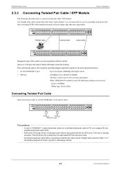
... auto negotiation. XG0448 Hardware Guide Chapter 2 Installation 2.3.3 Connecting Twisted Pair Cable / SFP Module The following settings are 'combination' ports that plugged equipment supports by default. (However, CX4 port only support 10Gbps full duplex mode fixed setting.) Ports automatically apply to 10/100/1000BASE-T port until it clicks. Media type, fixed at 100Mbps - Refer "2.3.1 Discharging Twisted Pair Cable" (pg.35) for discharging method. 37 Connecting the Equipment Use straight cable when connecting with transmission mode at fixed setting other switching...
... auto negotiation. XG0448 Hardware Guide Chapter 2 Installation 2.3.3 Connecting Twisted Pair Cable / SFP Module The following settings are 'combination' ports that plugged equipment supports by default. (However, CX4 port only support 10Gbps full duplex mode fixed setting.) Ports automatically apply to 10/100/1000BASE-T port until it clicks. Media type, fixed at 100Mbps - Refer "2.3.1 Discharging Twisted Pair Cable" (pg.35) for discharging method. 37 Connecting the Equipment Use straight cable when connecting with transmission mode at fixed setting other switching...
Hardware Guide
Page 41
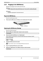
... (Unplug) Please refer to the follow instructions; 1. Unplug the USB memory from the switch. 4. Execute command "show usb hcd status [USB HCD STATUS] status : disable 3. Plug in crashing setting data. It may result in the replacing USB memory onto the switch. 5. Plug in from the interface panel of the USB port using the console command. # usbctl disable 2. Make the USB port to "disable status" using the console command. # usbctl enable 41 Connecting the Equipment XG0448 Hardware Guide Chapter 2 Installation 2.3.5 Plugging...
... (Unplug) Please refer to the follow instructions; 1. Unplug the USB memory from the switch. 4. Execute command "show usb hcd status [USB HCD STATUS] status : disable 3. Plug in crashing setting data. It may result in the replacing USB memory onto the switch. 5. Plug in from the interface panel of the USB port using the console command. # usbctl disable 2. Make the USB port to "disable status" using the console command. # usbctl enable 41 Connecting the Equipment XG0448 Hardware Guide Chapter 2 Installation 2.3.5 Plugging...
Hardware Guide
Page 42
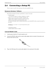
.... Reference User's Guide "1.1.5 Console Port Specifications" (pg.29) • Communication Software Terminal emulation software is to connect a set up PC to the console port of both the PC and the switch are off. 2. Confirm power of the switch. 42 Connecting a Setup PC XG0448 Hardware Guide 2.4 Connecting a Setup PC This is required. A RS232C crossover cable is required to connect the set up configuration is required. • RS232C crossover (null modem), D-SUB9F to the console port of the switch using RS232C cable. Connect RS232C Cable 1. Chapter 2 Installation...
.... Reference User's Guide "1.1.5 Console Port Specifications" (pg.29) • Communication Software Terminal emulation software is to connect a set up PC to the console port of both the PC and the switch are off. 2. Confirm power of the switch. 42 Connecting a Setup PC XG0448 Hardware Guide 2.4 Connecting a Setup PC This is required. A RS232C crossover cable is required to connect the set up configuration is required. • RS232C crossover (null modem), D-SUB9F to the console port of the switch using RS232C cable. Connect RS232C Cable 1. Chapter 2 Installation...
Hardware Guide
Page 44
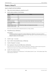
... the [Return] key or [Enter] key. will be displayed, then the "Login :" will be displayed again. XG0448 Hardware Guide Chapter 2 Installation Prepare a Setup PC Log on screen If the key in the wrong password, "invalid password." Press [Return] key or [Enter] key. Key in "admin" and press [Return] key or [Enter] key. 6. Start up the terminal software by using the terminal software. 1. Please wait for instructions on screen Setting 1 8 n/a 1 Asynchronous Communication System (Start-Stop Communication...
... the [Return] key or [Enter] key. will be displayed, then the "Login :" will be displayed again. XG0448 Hardware Guide Chapter 2 Installation Prepare a Setup PC Log on screen If the key in the wrong password, "invalid password." Press [Return] key or [Enter] key. Key in "admin" and press [Return] key or [Enter] key. 6. Start up the terminal software by using the terminal software. 1. Please wait for instructions on screen Setting 1 8 n/a 1 Asynchronous Communication System (Start-Stop Communication...

Hardware Guide
Page 47
... MAC Address Label 22 O Options 24 organization of the manuals 9 P Port Side 19 Power Cable 18 Power Inlet 22 Power Inlet Sid 22 Power Requirements 28 Prepare a Setup PC 44 Product Manufacturing Label 23 Product Part Number, Serial Number Label 19 PSU LED 20 R Rack Mounting Brackets 18 Ready LED 20 Redundant PSU Connector 22 Reset Switch 19 RS232C cable 42 S Safety and Installation Guide 18 SFP LED 20 SFP Link/Act LED 20 SFP Modules 24 SFP Slot 19 SFP+ Expansion Card...
... MAC Address Label 22 O Options 24 organization of the manuals 9 P Port Side 19 Power Cable 18 Power Inlet 22 Power Inlet Sid 22 Power Requirements 28 Prepare a Setup PC 44 Product Manufacturing Label 23 Product Part Number, Serial Number Label 19 PSU LED 20 R Rack Mounting Brackets 18 Ready LED 20 Redundant PSU Connector 22 Reset Switch 19 RS232C cable 42 S Safety and Installation Guide 18 SFP LED 20 SFP Link/Act LED 20 SFP Modules 24 SFP Slot 19 SFP+ Expansion Card...

