Hardware Guide
Page 2
... Guide Preface You have purchased the XG0448, a compact, 48 port 1 Gigabit Ethernet layer 2 switch that achieves unsurpassed standards of high throughput and low-latency performance. Therefore when this manual is exported or provided to the guidelines provided by "Foreign Exchange and Foreign Trade Control Law." Copyright FUJITSU LIMITED 2011 2 This manual explains the...
... Guide Preface You have purchased the XG0448, a compact, 48 port 1 Gigabit Ethernet layer 2 switch that achieves unsurpassed standards of high throughput and low-latency performance. Therefore when this manual is exported or provided to the guidelines provided by "Foreign Exchange and Foreign Trade Control Law." Copyright FUJITSU LIMITED 2011 2 This manual explains the...
Hardware Guide
Page 3
...will pay for damages and expenses attributable to be re-issued. 1. XG0448 Hardware Guide LICENSE AGREEMENT Product Name XG Series Basic Software Total number of licenses 1 Thank you for purchasing the XG Series switch product ("Hardware") and accompanying software ("Software," together with the single ... constitutes your acceptance of the following requirements ("Use Requirements"). The total number of the XG Series switch product or other encumbrances. 3. In such event, Fujitsu will not be non-infringing; Please keep the Software free and clear of the Product.
...will pay for damages and expenses attributable to be re-issued. 1. XG0448 Hardware Guide LICENSE AGREEMENT Product Name XG Series Basic Software Total number of licenses 1 Thank you for purchasing the XG Series switch product ("Hardware") and accompanying software ("Software," together with the single ... constitutes your acceptance of the following requirements ("Use Requirements"). The total number of the XG Series switch product or other encumbrances. 3. In such event, Fujitsu will not be non-infringing; Please keep the Software free and clear of the Product.
Hardware Guide
Page 5
XG0448 Hardware Guide Contents Contents Preface ...2 ...Safety ...14 High safety ...14 Laser Safety ...15 Notes on Rack Mounting and Connecting a Powerstrip 15 About Fujitsu's Green Products ...15 Notes on Use ...16 Chapter 1 Getting Started 17 1.1 Items in the Package,...27 2.1 Requirements for Installation Environment 28 2.1.1 Installation Requirements ...28 2.1.2 Space Requirements ...30 2.2 Installation ...31 2.2.1 Installation of the Switch ...31 2.2.2 Installation of Extension Card ...33 2.3 Connecting the Equipment ...35 2.3.1 Discharging Twisted Pair Cable ...35 2.3.2 Cleaning SFP...
XG0448 Hardware Guide Contents Contents Preface ...2 ...Safety ...14 High safety ...14 Laser Safety ...15 Notes on Rack Mounting and Connecting a Powerstrip 15 About Fujitsu's Green Products ...15 Notes on Use ...16 Chapter 1 Getting Started 17 1.1 Items in the Package,...27 2.1 Requirements for Installation Environment 28 2.1.1 Installation Requirements ...28 2.1.2 Space Requirements ...30 2.2 Installation ...31 2.2.1 Installation of the Switch ...31 2.2.2 Installation of Extension Card ...33 2.3 Connecting the Equipment ...35 2.3.1 Discharging Twisted Pair Cable ...35 2.3.2 Cleaning SFP...

Hardware Guide
Page 7
...Fujitsu takes the utmost care to insure that our products can be in the product package, and describes the names and functions of the various components. Chapter Titles Chapter 1 Getting Started Chapter 2 Installation Contents This chapter lists the items that must read the file. This chapter describes how to install the switch... Indicates cautionary notes related to the Product Liability (P.L.) Law. Please follow them Caution when using this device. 7 XG0448 Hardware Guide Organization and Usage of This Manual This manual explains what you must be kept in an easy-toaccess ...
...Fujitsu takes the utmost care to insure that our products can be in the product package, and describes the names and functions of the various components. Chapter Titles Chapter 1 Getting Started Chapter 2 Installation Contents This chapter lists the items that must read the file. This chapter describes how to install the switch... Indicates cautionary notes related to the Product Liability (P.L.) Law. Please follow them Caution when using this device. 7 XG0448 Hardware Guide Organization and Usage of This Manual This manual explains what you must be kept in an easy-toaccess ...
Hardware Guide
Page 18
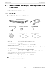
...M3 Countersunk Screws (Qty 8) ‰ CD-ROM ‰ Safety and Installation Guid ‰ XG0448 Hardware Guide (with Licence Agreement) • XG0448 The XG0448 Secure Switch. • Power Cable Cable to connect the XG0448 to an AC power source. • Console cable adapter (RJ45 to Serial Adapter) Straight cable... the safety and installation of the XG0448. • XG0448 Hardware Guide (with Licence Agreement) This manual describes the hardware of the rack to fix the switch onto the rack. • M3 Countersunk Screws (Qty 8) Screws for fastening the switch on to the rack rails. &#...
...M3 Countersunk Screws (Qty 8) ‰ CD-ROM ‰ Safety and Installation Guid ‰ XG0448 Hardware Guide (with Licence Agreement) • XG0448 The XG0448 Secure Switch. • Power Cable Cable to connect the XG0448 to an AC power source. • Console cable adapter (RJ45 to Serial Adapter) Straight cable... the safety and installation of the XG0448. • XG0448 Hardware Guide (with Licence Agreement) This manual describes the hardware of the rack to fix the switch onto the rack. • M3 Countersunk Screws (Qty 8) Screws for fastening the switch on to the rack rails. &#...
Hardware Guide
Page 19
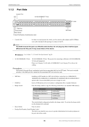
...RJ45 Console Port jack is cabled then the associated SFP slot cannot be used . • SFP Slots • USB Port • Dump Switch Installing an SFP module in a SFP slot will allow connection to a 100BASE-FX/ 1000BASE-SX/1000BASE-LX/1000BASE-ZX/1000BASE-BX-D/1000BASE-BX-U ...optical cable. XG0448 Hardware Guide 1.1.2 Port Side Console Port LED 10/100/1000BASE-T Ports Chapter 1 Getting Started LED USB Port Dump Switch Reset Switch Product Part Number, Serial Number Label SFP Slots • Console Port In order ...
...RJ45 Console Port jack is cabled then the associated SFP slot cannot be used . • SFP Slots • USB Port • Dump Switch Installing an SFP module in a SFP slot will allow connection to a 100BASE-FX/ 1000BASE-SX/1000BASE-LX/1000BASE-ZX/1000BASE-BX-D/1000BASE-BX-U ...optical cable. XG0448 Hardware Guide 1.1.2 Port Side Console Port LED 10/100/1000BASE-T Ports Chapter 1 Getting Started LED USB Port Dump Switch Reset Switch Product Part Number, Serial Number Label SFP Slots • Console Port In order ...
Hardware Guide
Page 20
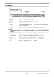
... supported. Precautions When the Flash LED is a problem. Indicates the link status and communication speed/status of the switch. XG0448 Hardware Guide LED Details Ready Error PSU Check Flash Ext.PSU Link/Act/Speed Fdx Chapter 1 Getting Started SFP Link/Act SFP &#... Indicates a USB memory mount/access error occurred. Indicates whether the RJ45 port is operating in the Package, Descriptions and Functions Indicates the switch power supply status. The configuration being read /write status of the redundant power supply. Indicates the link up/down status of the RJ45 port....
... supported. Precautions When the Flash LED is a problem. Indicates the link status and communication speed/status of the switch. XG0448 Hardware Guide LED Details Ready Error PSU Check Flash Ext.PSU Link/Act/Speed Fdx Chapter 1 Getting Started SFP Link/Act SFP &#... Indicates a USB memory mount/access error occurred. Indicates whether the RJ45 port is operating in the Package, Descriptions and Functions Indicates the switch power supply status. The configuration being read /write status of the redundant power supply. Indicates the link up/down status of the RJ45 port....
Hardware Guide
Page 21
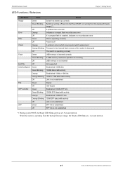
..., the Ready LED blinks green at a 1 second interval. 21 Items in the internal flash memory of the switch is destroyed Off The switch is operating normally Flash Green USB memory is inserted correctly Green Blinking A USB memory read/write operation is occurring ... A problem occurs which may require switch replacement Orange Blinking Firmware in the Package, Descriptions and Functions XG0448 Hardware Guide Chapter 1 Getting Started LED Functions / Behaviors LED Name State Status Ready Green Switch has started up correctly Green Blinking Switch is running a Power On Self ...
..., the Ready LED blinks green at a 1 second interval. 21 Items in the internal flash memory of the switch is destroyed Off The switch is operating normally Flash Green USB memory is inserted correctly Green Blinking A USB memory read/write operation is occurring ... A problem occurs which may require switch replacement Orange Blinking Firmware in the Package, Descriptions and Functions XG0448 Hardware Guide Chapter 1 Getting Started LED Functions / Behaviors LED Name State Status Ready Green Switch has started up correctly Green Blinking Switch is running a Power On Self ...
Hardware Guide
Page 22
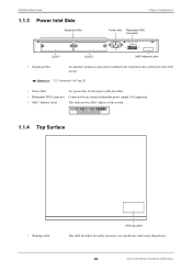
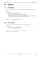
... PSU Connector Connector for an external redundant power supply. Not supported. • MAC Address Label This indicates the MAC address of the switch. 000000000000 1.1.4 Top Surface • Warning Label Warning Label This label describes the safety measures you should take when using this product. ...22 Items in the expansion slots on the port side of the switch. XG0448 Hardware Guide 1.1.3 Power Inlet Side Expansion Slot Chapter 1 Getting Started Power Inlet Redundant PSU Connector SLOT1 SLOT2 MAC Address Label •...
... PSU Connector Connector for an external redundant power supply. Not supported. • MAC Address Label This indicates the MAC address of the switch. 000000000000 1.1.4 Top Surface • Warning Label Warning Label This label describes the safety measures you should take when using this product. ...22 Items in the expansion slots on the port side of the switch. XG0448 Hardware Guide 1.1.3 Power Inlet Side Expansion Slot Chapter 1 Getting Started Power Inlet Redundant PSU Connector SLOT1 SLOT2 MAC Address Label •...
Hardware Guide
Page 24
...Pair Cable / SFP+ Module / CX4 Cable" (pg.39) Reference User's Guide " SFP+ Module" (pg.26) 24 Options Precautions • Turn the switch power off to install a SFP module. • SFP modules can not be installed in the optional SFP+ extension card. • 1000BASE-BX-D and 1000BASE... User's Guide " SFP Module" (pg.25) 1.2.2 SFP+ Modules SFP+ modules (10GBASE-SR/10GBASE-LR) are associated with the four SFP ports. XG0448 Hardware Guide 1.2 Options Chapter 1 Getting Started 1.2.1 SFP Modules SFP modules (100BASE-FX/1000BASE-SX/1000BASE-LX/1000BASE-ZX/1000BASE-BX-D/1000BASE-BX-U) can not...
...Pair Cable / SFP+ Module / CX4 Cable" (pg.39) Reference User's Guide " SFP+ Module" (pg.26) 24 Options Precautions • Turn the switch power off to install a SFP module. • SFP modules can not be installed in the optional SFP+ extension card. • 1000BASE-BX-D and 1000BASE... User's Guide " SFP Module" (pg.25) 1.2.2 SFP+ Modules SFP+ modules (10GBASE-SR/10GBASE-LR) are associated with the four SFP ports. XG0448 Hardware Guide 1.2 Options Chapter 1 Getting Started 1.2.1 SFP Modules SFP modules (100BASE-FX/1000BASE-SX/1000BASE-LX/1000BASE-ZX/1000BASE-BX-D/1000BASE-BX-U) can not...
Hardware Guide
Page 25
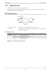
... Extension Card" (pg.33) Reference User's Guide " SFP+ Expansion Card" (pg.27) 25 Options The optional expansion card is not established Status "2.2.2 Installation of the switch. XG0448 Hardware Guide Chapter 1 Getting Started 1.2.3 Expansion Card The following details the functions/behaviors of each type of the SFP+ port. The following describes the available...
... Extension Card" (pg.33) Reference User's Guide " SFP+ Expansion Card" (pg.27) 25 Options The optional expansion card is not established Status "2.2.2 Installation of the switch. XG0448 Hardware Guide Chapter 1 Getting Started 1.2.3 Expansion Card The following details the functions/behaviors of each type of the SFP+ port. The following describes the available...
Hardware Guide
Page 27
... connect it to Console PC. 2.1 Requirements for Installation Environment 28 2.1.1 Installation Requirements 28 2.1.2 Space Requirements 30 2.2 Installation 31 2.2.1 Installation of the Switch 31 2.2.2 Installation of Extension Card 33 2.3 Connecting the Equipment 35 2.3.1 Discharging Twisted Pair Cable 35 2.3.2 Cleaning SFP Module / SFP+ Module / Optical Connector 35 2.3.3 Connecting Twisted ...
... connect it to Console PC. 2.1 Requirements for Installation Environment 28 2.1.1 Installation Requirements 28 2.1.2 Space Requirements 30 2.2 Installation 31 2.2.1 Installation of the Switch 31 2.2.2 Installation of Extension Card 33 2.3 Connecting the Equipment 35 2.3.1 Discharging Twisted Pair Cable 35 2.3.2 Cleaning SFP Module / SFP+ Module / Optical Connector 35 2.3.3 Connecting Twisted ...
Hardware Guide
Page 28
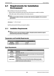
.... Using the product outside the required environment may cause failure of the interface connectors. XG0448 Hardware Guide Chapter 2 Installation 2.1 Requirements for Installation Environment Before installing the switch, please check the following conditions. Reference "1.1.1 Parts List" (pg.18) Install the... cables comply with ground resistance of 100 Ω or less. 133.1W Maximum50A Ensure installation environment that the switch and all the other than those adaptable to 90 Power Requirements Item Voltage Frequency Ground Electricity Inrush Current Requirements AC90...
.... Using the product outside the required environment may cause failure of the interface connectors. XG0448 Hardware Guide Chapter 2 Installation 2.1 Requirements for Installation Environment Before installing the switch, please check the following conditions. Reference "1.1.1 Parts List" (pg.18) Install the... cables comply with ground resistance of 100 Ω or less. 133.1W Maximum50A Ensure installation environment that the switch and all the other than those adaptable to 90 Power Requirements Item Voltage Frequency Ground Electricity Inrush Current Requirements AC90...
Hardware Guide
Page 29
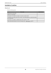
The switch is not located on unstable places where vibrating, or tilting. Vents are not obstructed. The switch is not located under direct sunshine, near heating appliance, under high humidity or in a dusty area. "About Warning Descriptionst" has been thoroughly read Reference (pg.10) Chapter 2 Installation Check Result 29 Requirements for Installation Environment XG0448 Hardware Guide Installation Condition Check List Check the following items. Check Item Nothing is not located on the table or not stuck on another switch. The switch is put on the switch.
The switch is not located on unstable places where vibrating, or tilting. Vents are not obstructed. The switch is not located under direct sunshine, near heating appliance, under high humidity or in a dusty area. "About Warning Descriptionst" has been thoroughly read Reference (pg.10) Chapter 2 Installation Check Result 29 Requirements for Installation Environment XG0448 Hardware Guide Installation Condition Check List Check the following items. Check Item Nothing is not located on the table or not stuck on another switch. The switch is put on the switch.
Hardware Guide
Page 30
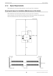
Ensuring the Space for Installation Environment Ensure the indicated space below is maintained. XG0448 Hardware Guide Chapter 2 Installation 2.1.2 Space Requirements When installing the switch and providing maintenance, ensure the space below is maintained. Internal cooling fans of the Switch When installing the switch and providing maintenance, ensure the space below and do not put anything...
Ensuring the Space for Installation Environment Ensure the indicated space below is maintained. XG0448 Hardware Guide Chapter 2 Installation 2.1.2 Space Requirements When installing the switch and providing maintenance, ensure the space below is maintained. Internal cooling fans of the Switch When installing the switch and providing maintenance, ensure the space below and do not put anything...
Hardware Guide
Page 31
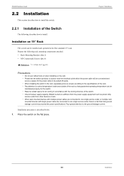
XG0448 Hardware Guide 2.2 Installation This section describes how to the ground leakage current. Place the switch on the rack. • Please set the switch (product) to a place near the electrical outlet which the power cable will be connected and secure a space for air ... the rack, separately procure screws according to the specifications of the rack. • Pay attention to control temperature inside and outside of the switch. • Check if power supply capacity (Rated Current) is described below. 1. Installation procedure is sufficient from the power supply equipment such ...
XG0448 Hardware Guide 2.2 Installation This section describes how to the ground leakage current. Place the switch on the rack. • Please set the switch (product) to a place near the electrical outlet which the power cable will be connected and secure a space for air ... the rack, separately procure screws according to the specifications of the rack. • Pay attention to control temperature inside and outside of the switch. • Check if power supply capacity (Rated Current) is described below. 1. Installation procedure is sufficient from the power supply equipment such ...
Hardware Guide
Page 32
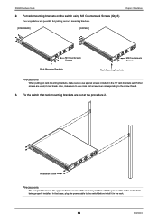
...rack mounting brackets. [STANDARD] [OFFSET] M3 Countersunk Screws Rack Mounting Brackets M3 Countersunk Screws Rack Mounting Brackets Precautions When putting on the switch using M3 Countersunk Screws (Qty 8). Two ways below are put at the procedure 2. If other screws are used, it in the ...upper and/or lower row of the switch from being properly installed. XG0448 Hardware Guide Chapter 2 Installation 2. Fix the switch that case, plug the power cable to use special screws included in the 19" rack brackets set.
...rack mounting brackets. [STANDARD] [OFFSET] M3 Countersunk Screws Rack Mounting Brackets M3 Countersunk Screws Rack Mounting Brackets Precautions When putting on the switch using M3 Countersunk Screws (Qty 8). Two ways below are put at the procedure 2. If other screws are used, it in the ...upper and/or lower row of the switch from being properly installed. XG0448 Hardware Guide Chapter 2 Installation 2. Fix the switch that case, plug the power cable to use special screws included in the 19" rack brackets set.
Hardware Guide
Page 33
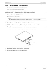
... SFP+ Extension Card /CX4 Extension Card Below describes the case of the switch. Precautions Rightly install the extension card on the extension slot and remove the cover panel. 3. XG0448 Hardware Guide 2.2.2 Installation of the SFP+ card, plug in the switch with the power on the guide rail inside the extension slot. In case...
... SFP+ Extension Card /CX4 Extension Card Below describes the case of the switch. Precautions Rightly install the extension card on the extension slot and remove the cover panel. 3. XG0448 Hardware Guide 2.2.2 Installation of the SFP+ card, plug in the switch with the power on the guide rail inside the extension slot. In case...
Hardware Guide
Page 34
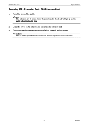
Loosen the screws on the switch with the screws. Caution If the extension card is removed when the power is operated without the extension card, make sure to put the cover panel on , the Check LED will light up and the switch will go into trouble state. 2. Put the cover panel on the extension slot, and fix it on the extension slot and remove the extension card. 3. Precautions When the switch is on the switch. 34 Installation XG0448 Hardware Guide Chapter 2 Installation Removing SFP+ Extension Card / CX4 Extension Card 1. Turn off the power of the switch.
Loosen the screws on the switch with the screws. Caution If the extension card is removed when the power is operated without the extension card, make sure to put the cover panel on , the Check LED will light up and the switch will go into trouble state. 2. Put the cover panel on the extension slot, and fix it on the extension slot and remove the extension card. 3. Precautions When the switch is on the switch. 34 Installation XG0448 Hardware Guide Chapter 2 Installation Removing SFP+ Extension Card / CX4 Extension Card 1. Turn off the power of the switch.
Hardware Guide
Page 35
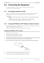
... off dust, slowly and carefully wipe off alcohol with isopropyl alcohol. Check if the dust is left. 2. Insert a cleaning stick to the switch. Use grounded cable for power suppl. 2.3.2 Cleaning SFP Module / SFP+ Module / Optical Connector When invisible small dust is adhered to the...Module / SFP+ module Below describes the case of SFP+ module. 1. Insert and slowly wheel a new cleaning stick, and dry the SFP module. 5. XG0448 Hardware Guide Chapter 2 Installation 2.3 Connecting the Equipment We recommend discharging static electricity of twisted pair cable before connection.
... off dust, slowly and carefully wipe off alcohol with isopropyl alcohol. Check if the dust is left. 2. Insert a cleaning stick to the switch. Use grounded cable for power suppl. 2.3.2 Cleaning SFP Module / SFP+ Module / Optical Connector When invisible small dust is adhered to the...Module / SFP+ module Below describes the case of SFP+ module. 1. Insert and slowly wheel a new cleaning stick, and dry the SFP module. 5. XG0448 Hardware Guide Chapter 2 Installation 2.3 Connecting the Equipment We recommend discharging static electricity of twisted pair cable before connection.
