Configuration Guide PDF
Page 1
... box for proper installation. The Dockside Wizard and the Sea Trial Wizard are responsible for configuration using a compatible chartplotter on the autopilot. Performing the Dockside Wizard NOTICE If you complete the wizard. If this equipment in accordance with a power assist steering system, turn the boat to the rudder or other objects. REACTOR™ 40 HYDRAULIC Configuration Guide Important Safety...
... box for proper installation. The Dockside Wizard and the Sea Trial Wizard are responsible for configuration using a compatible chartplotter on the autopilot. Performing the Dockside Wizard NOTICE If you complete the wizard. If this equipment in accordance with a power assist steering system, turn the boat to the rudder or other objects. REACTOR™ 40 HYDRAULIC Configuration Guide Important Safety...

Configuration Guide PDF
Page 2
... in the Sea Trial Wizard, do not align, there may be a problem with the speed source set to Tachometer - NOTE: Garmin® recommends using an external GPS antenna as the speed source. If the RPM numbers do not move around on a chartplotter, select Settings > My Vessel > Autopilot Installation Setup > Autopilot Tuning > Autotune > Begin. Because the nature of calm water is...
... in the Sea Trial Wizard, do not align, there may be a problem with the speed source set to Tachometer - NOTE: Garmin® recommends using an external GPS antenna as the speed source. If the RPM numbers do not move around on a chartplotter, select Settings > My Vessel > Autopilot Installation Setup > Autopilot Tuning > Autotune > Begin. Because the nature of calm water is...

Configuration Guide PDF
Page 3
... setting if the autopilot turns too slowly. Counter Gain: Sets how aggressively the autopilot adjusts any over Ground (COG) information from the heading screen, select Menu > Setup > Dealer Autopilot Setup > Autopilot Tuning > Acceleration Limiter. • On a chartplotter, select Settings > My Vessel > Autopilot Installation Setup > Autopilot Tuning > Accel. During this procedure as part of the Sea Trial Wizard, proceed to drive the boat in one direction using the autopilot...
... setting if the autopilot turns too slowly. Counter Gain: Sets how aggressively the autopilot adjusts any over Ground (COG) information from the heading screen, select Menu > Setup > Dealer Autopilot Setup > Autopilot Tuning > Acceleration Limiter. • On a chartplotter, select Settings > My Vessel > Autopilot Installation Setup > Autopilot Tuning > Accel. During this procedure as part of the Sea Trial Wizard, proceed to drive the boat in one direction using the autopilot...

Configuration Guide PDF
Page 4
... GPS, select Low Speed or High Speed and adjust how tightly the rudder holds the heading and makes turns at the slightest deviation. If so, you to find an ideal mounting location for 5 seconds. Selecting a Preferred Source of the setting. An overactive autopilot can drain the battery at a faster-than that from the heading screen, select Menu > Setup...
... GPS, select Low Speed or High Speed and adjust how tightly the rudder holds the heading and makes turns at the slightest deviation. If so, you to find an ideal mounting location for 5 seconds. Selecting a Preferred Source of the setting. An overactive autopilot can drain the battery at a faster-than that from the heading screen, select Menu > Setup...
Configuration Guide PDF
Page 5
... a chartplotter, select Settings > My Vessel > Autopilot Installation Setup > Rudder Gains. Counter Gain: Allows you to adjust the planing speed of turns it takes to adjust how tightly the rudder corrects turn . If you can use this calibration if the on-screen rudder position indicator does not match the true rudder center on the helm, near the hydraulic connectors. NMEA...
... a chartplotter, select Settings > My Vessel > Autopilot Installation Setup > Rudder Gains. Counter Gain: Allows you to adjust the planing speed of turns it takes to adjust how tightly the rudder corrects turn . If you can use this calibration if the on-screen rudder position indicator does not match the true rudder center on the helm, near the hydraulic connectors. NMEA...

Configuration Guide PDF
Page 6
Ang.: Allows you to enter the angle at which your rudder turns furthest starboard. © 2017 Garmin Ltd. or its subsidiaries Garmin® and the Garmin logo are trademarks of the National Marine Electronics Association. or its subsidiaries. Reactor™ and Shadow Drive™ are trademarks of Garmin Ltd. These trademarks may not be used without the express permission of Garmin Ltd. Stbd. Starboard Angle or Max. Max. or its subsidiaries, registered in the USA and other countries. NMEA®, NMEA 2000®, and the NMEA 2000 logo are trademarks of Garmin.
Ang.: Allows you to enter the angle at which your rudder turns furthest starboard. © 2017 Garmin Ltd. or its subsidiaries Garmin® and the Garmin logo are trademarks of the National Marine Electronics Association. or its subsidiaries. Reactor™ and Shadow Drive™ are trademarks of Garmin Ltd. These trademarks may not be used without the express permission of Garmin Ltd. Stbd. Starboard Angle or Max. Max. or its subsidiaries, registered in the USA and other countries. NMEA®, NMEA 2000®, and the NMEA 2000 logo are trademarks of Garmin.
Installation Instructions PDF
Page 1
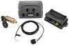
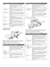
...support you by a qualified marine installer. You can use mounting hardware other and to the centerline of the boat. • The best location is lower in the boat. • The best location is the primary sensor of the Reactor 40 Hydraulic autopilot system. If needed, extension cables...correctly plan the installation on calm and hazard-free open water. If more than one location is approximately the same distance from www.garmin.com. REACTOR™ 40 HYDRAULIC Installation Instructions Important Safety Information WARNING See the Important Safety and Product Information guide in the ...
...support you by a qualified marine installer. You can use mounting hardware other and to the centerline of the boat. • The best location is lower in the boat. • The best location is the primary sensor of the Reactor 40 Hydraulic autopilot system. If needed, extension cables...correctly plan the installation on calm and hazard-free open water. If more than one location is approximately the same distance from www.garmin.com. REACTOR™ 40 HYDRAULIC Installation Instructions Important Safety Information WARNING See the Important Safety and Product Information guide in the ...
Installation Instructions PDF
Page 2
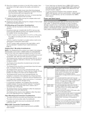
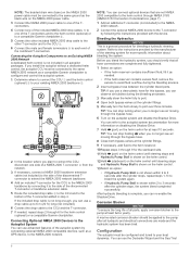
... the in all autopilot packages. NMEA 2000® Connection Considerations • The CCU and the helm control must connect the NMEA 2000 power cable to a 9 to 16 Vdc power source. Do not install this process while moving the compass in the product specifications. If there is not included in -line fuse holder. You should be mounted near the...
... the in all autopilot packages. NMEA 2000® Connection Considerations • The CCU and the helm control must connect the NMEA 2000 power cable to a 9 to 16 Vdc power source. Do not install this process while moving the compass in the product specifications. If there is not included in -line fuse holder. You should be mounted near the...
Installation Instructions PDF
Page 3
... Vdc power source. Detailed installation instructions are not shown in this cable to use the correct wire gauge (Power Cable Extensions, page 4). If there is not an existing NMEA 2000 network on your boat, you install the autopilot without a dedicated helm control, the autopilot CCU must connect the helm control or compatible Garmin chartplotter and the CCU to 24 Vdc à battery Important...
... Vdc power source. Detailed installation instructions are not shown in this cable to use the correct wire gauge (Power Cable Extensions, page 4). If there is not an existing NMEA 2000 network on your boat, you install the autopilot without a dedicated helm control, the autopilot CCU must connect the helm control or compatible Garmin chartplotter and the CCU to 24 Vdc à battery Important...
Installation Instructions PDF
Page 4
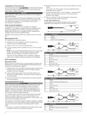
... a 40 A fuse. After you install all of the mounting and wiring considerations for the length of the ECU power cable to the ECU, but do not remove the in .) bit, drill the pilot holes. 4 Use the included screws to attach the CCU to 15 ft. (4.6 m) Item Description Splice 8 AWG (8.36 mm²) extension wire Fuse 8 in. (20.3 cm) Battery 8 in all autopilot...
... a 40 A fuse. After you install all of the mounting and wiring considerations for the length of the ECU power cable to the ECU, but do not remove the in .) bit, drill the pilot holes. 4 Use the included screws to attach the CCU to 15 ft. (4.6 m) Item Description Splice 8 AWG (8.36 mm²) extension wire Fuse 8 in. (20.3 cm) Battery 8 in all autopilot...
Installation Instructions PDF
Page 5
..." chapter of your boat (Shadow Drive™ Mounting Considerations, page 2). To use the advanced features of the autopilot, optional NMEA 2000 devices, such as a GPS device, can be installed in your battery if the NMEA 2000 power cable is not included in all autopilot packages. If you must select a location at www.garmin.com. A dedicated helm control is connected to...
..." chapter of your boat (Shadow Drive™ Mounting Considerations, page 2). To use the advanced features of the autopilot, optional NMEA 2000 devices, such as a GPS device, can be installed in your battery if the NMEA 2000 power cable is not included in all autopilot packages. If you must select a location at www.garmin.com. A dedicated helm control is connected to...
Installation Instructions PDF
Page 6
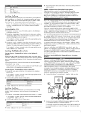
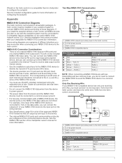
Connecting Optional NMEA 2000 Devices to the Autopilot System You can use a clear plastic hose for at the cylinder fittings. 5 Manually turn the helm slowly to port over three minutes. NOTE: You can refer to the autopilot system documentation for more -specific information about bleeding the system. Refer to the instructions provided by connecting it as needed , repeat...
Connecting Optional NMEA 2000 Devices to the Autopilot System You can use a clear plastic hose for at the cylinder fittings. 5 Manually turn the helm slowly to port over three minutes. NOTE: You can refer to the autopilot system documentation for more -specific information about bleeding the system. Refer to the instructions provided by connecting it as needed , repeat...
Installation Instructions PDF
Page 7
...; There is connected to TXA on the data cable, you can connect the output port of your NMEA 0183 device to the input port on the wiring harness. • See Specifications, page 8 for a list of the approved ...autopilot. NMEA 2000 network (provides power to the blue wire (Tx/A) from the helm control, and leave the white wire (Tx/B) from the helm control unconnected. A helm control must be connected to power ground. • The power cable from this Garmin device. • See the installation instructions for more information on the helm control or a compatible Garmin chartplotter to use...
...; There is connected to TXA on the data cable, you can connect the output port of your NMEA 0183 device to the input port on the wiring harness. • See Specifications, page 8 for a list of the approved ...autopilot. NMEA 2000 network (provides power to the blue wire (Tx/A) from the helm control, and leave the white wire (Tx/B) from the helm control unconnected. A helm control must be connected to power ground. • The power cable from this Garmin device. • See the installation instructions for more information on the helm control or a compatible Garmin chartplotter to use...
Installation Instructions PDF
Page 8
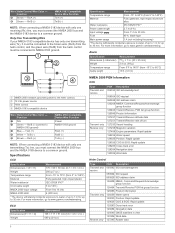
... update 129283 Cross track error 129284 Navigation data 129540 GNSS satellites in . (23 × 25 mm) 2.4 oz. (68 g) From 5°F to 140°F (from 5° to 140°F) Material Fully gasketed, high-impact aluminum alloy Water resistance IEC 60529 IPX7* Power cable length 2.7 m (9 ft.) Input voltage From 11.5 to 30 Vdc Fuse 40 A, blade-type Main power...
... update 129283 Cross track error 129284 Navigation data 129540 GNSS satellites in . (23 × 25 mm) 2.4 oz. (68 g) From 5°F to 140°F (from 5° to 140°F) Material Fully gasketed, high-impact aluminum alloy Water resistance IEC 60529 IPX7* Power cable length 2.7 m (9 ft.) Input voltage From 11.5 to 30 Vdc Fuse 40 A, blade-type Main power...
Installation Instructions PDF
Page 9
... to your Garmin account. or its subsidiaries Garmin® and the Garmin logo are trademarks of the National Marine Electronics Association. 9 These trademarks may not be used without the express permission of Garmin Ltd. Autopilot placed data while performing a in to autopilot is no longer receiving navigation receiving valid navigation data. Low GHC™ Supply Voltage Error: ECU High...
... to your Garmin account. or its subsidiaries Garmin® and the Garmin logo are trademarks of the National Marine Electronics Association. 9 These trademarks may not be used without the express permission of Garmin Ltd. Autopilot placed data while performing a in to autopilot is no longer receiving navigation receiving valid navigation data. Low GHC™ Supply Voltage Error: ECU High...


