

Installation Manual
Page 1
NetworX™ Series NX-1710E Single Door Control Installation and Startup Manual
NetworX™ Series NX-1710E Single Door Control Installation and Startup Manual
Installation Manual
Page 2
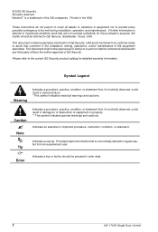
... helpful information that customer in regular use, but from an experienced user. © 2005 GE Security All rights reserved. NetworX™ is a trademark of GE Security. This document contains proprietary information of equipment or property. ** This symbol indicates general warnings and cautions. Tip Enter Indicates a key or button should be disclosed to enter data. 2 NX-1710E Single Door Control Caution Note Indicates a procedure, practice, condition...
... helpful information that customer in regular use, but from an experienced user. © 2005 GE Security All rights reserved. NetworX™ is a trademark of GE Security. This document contains proprietary information of equipment or property. ** This symbol indicates general warnings and cautions. Tip Enter Indicates a key or button should be disclosed to enter data. 2 NX-1710E Single Door Control Caution Note Indicates a procedure, practice, condition...
Installation Manual
Page 3
......35 XII. SPECIFICATIONS...36 Main 800-727-2339 Outside the US 903-845-6941 Main Fax 903-845-6811 Web: www.ge-security.com Technical Support 800-727-2339 Tech Support Fax 903-845-8409 Sales & Literature 800-547-2556 NX-1710E Single Door Control 3 PROGRAMMING LOCATIONS 11 IX. USER CARDS ...9 VIII. UNDERWRITERS LABORATORIES INFORMATION 36 XIV. ADDRESSING...7 VI. BOARD LAYOUT...5 III. GENERAL DESCRIPTION 4 II...
......35 XII. SPECIFICATIONS...36 Main 800-727-2339 Outside the US 903-845-6941 Main Fax 903-845-6811 Web: www.ge-security.com Technical Support 800-727-2339 Tech Support Fax 903-845-8409 Sales & Literature 800-547-2556 NX-1710E Single Door Control 3 PROGRAMMING LOCATIONS 11 IX. USER CARDS ...9 VIII. UNDERWRITERS LABORATORIES INFORMATION 36 XIV. ADDRESSING...7 VI. BOARD LAYOUT...5 III. GENERAL DESCRIPTION 4 II...
Installation Manual
Page 4
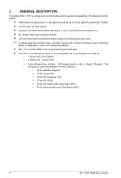
... expand the capabilities of the NetworX control panels. • Flash-based microprocessor for reprogramming ability via In-Circuit Serial Programming™ header • +5 VDC and +12 VDC outputs • 4-position dip switch which allows addressing of terminal inputs/outputs for interfacing with facility code (Casi Rusco 4001) 40-bit without facility code (Casi Rusco 4002) 4 NX-1710E Single Door Control The following are supported Weigand formats by default...
... expand the capabilities of the NetworX control panels. • Flash-based microprocessor for reprogramming ability via In-Circuit Serial Programming™ header • +5 VDC and +12 VDC outputs • 4-position dip switch which allows addressing of terminal inputs/outputs for interfacing with facility code (Casi Rusco 4001) 40-bit without facility code (Casi Rusco 4002) 4 NX-1710E Single Door Control The following are supported Weigand formats by default...
Installation Manual
Page 5
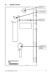
Programmer NX-1710E Single Door Control Dip Switches (see pg 7 for specifics.) 5 BOARD LAYOUT NetworX bus LED is lit during normal operation. II.
Programmer NX-1710E Single Door Control Dip Switches (see pg 7 for specifics.) 5 BOARD LAYOUT NetworX bus LED is lit during normal operation. II.
Installation Manual
Page 6
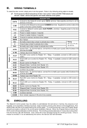
..., connect to all keypads, zone expanders, wireless receivers, output modules, and any other device on reader. If available, connect to the system. Door contact (requires 3.3K end-of all the devices on reader. Reader "B" IV. This allows these instructions, the term "door control" refers to the NX-1710E module, and the term "reader" refers to the specific card reader attached to LED control on reader. To enroll the devices, enter the Program Mode using...
..., connect to all keypads, zone expanders, wireless receivers, output modules, and any other device on reader. If available, connect to the system. Door contact (requires 3.3K end-of all the devices on reader. Reader "B" IV. This allows these instructions, the term "door control" refers to the NX-1710E module, and the term "reader" refers to the specific card reader attached to LED control on reader. To enroll the devices, enter the Program Mode using...
Installation Manual
Page 7
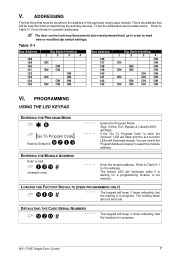
.... The door control unit must be entered. Refer to select the module address. This is the address that the loading is waiting for the address. You are now in progress. The Armed LED will beep 3 times indicating that must be selected when programming the auxiliary devices. PROGRAMMING USING THE LED KEYPAD ENTERING THE PROGRAM MODE [Go To Program Code] Factory Default is the address of this particular relay/output module. Stay, Chime, Exit, Bypass & Cancel LEDS will...
.... The door control unit must be entered. Refer to select the module address. This is the address that the loading is waiting for the address. You are now in progress. The Armed LED will beep 3 times indicating that must be selected when programming the auxiliary devices. PROGRAMMING USING THE LED KEYPAD ENTERING THE PROGRAM MODE [Go To Program Code] Factory Default is the address of this particular relay/output module. Stay, Chime, Exit, Bypass & Cancel LEDS will...
Installation Manual
Page 8
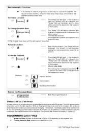
... flash. To Review The Data: [ ] location # Shortcuts: The Armed LED will increment and display the next segment's data. Same location. Next sequential location. USING THE LCD KEYPAD All steps required for the first segment of the next segment will be entered. Feature Selection Data is saved. The new data is used to turn features on or off. 8 NX-1710E Single Door Control The "Ready" LED will display a hyphen (-). Each time...
... flash. To Review The Data: [ ] location # Shortcuts: The Armed LED will increment and display the next segment's data. Same location. Next sequential location. USING THE LCD KEYPAD All steps required for the first segment of the next segment will be entered. Feature Selection Data is saved. The new data is used to turn features on or off. 8 NX-1710E Single Door Control The "Ready" LED will display a hyphen (-). Each time...
Installation Manual
Page 9
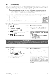
... door control on a door control is not incremented in order to program user cards, so... ADDING ONE USER [STAY] [ ] 3-digit user number Example: if 4-digit user code or if 6-digit Scan the card designated for you to flash. If the card is enabled to the entered user number and LED1 (Green) will continue flashing; Therefore, it must be entered, one of entering information at a keypad. NX-1710E Single Door Control 9 ENTER USER PROGRAMMING Accesses Code Programming [master code] Factory Default is if control is an NX-4, NX-6, or NX...
... door control on a door control is not incremented in order to program user cards, so... ADDING ONE USER [STAY] [ ] 3-digit user number Example: if 4-digit user code or if 6-digit Scan the card designated for you to flash. If the card is enabled to the entered user number and LED1 (Green) will continue flashing; Therefore, it must be entered, one of entering information at a keypad. NX-1710E Single Door Control 9 ENTER USER PROGRAMMING Accesses Code Programming [master code] Factory Default is if control is an NX-4, NX-6, or NX...
Installation Manual
Page 10
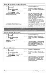
... readers will begin to the entered user number and LED1 (Green) will be updated. 10 NX-1710E Single Door Control ACTIVATE ONE USER (SINGLE USER) [CHIME] [ ] 3-digit user number Example: if 4-digit user code or if 6-digit Scan any enabled readers will begin to flash. The card information for the user entered in the previous step will be cleared, and LED1 (Green) will stop flashing. The card information for the user entered in the previous step will...
... readers will begin to the entered user number and LED1 (Green) will be updated. 10 NX-1710E Single Door Control ACTIVATE ONE USER (SINGLE USER) [CHIME] [ ] 3-digit user number Example: if 4-digit user code or if 6-digit Scan any enabled readers will begin to flash. The card information for the user entered in the previous step will be cleared, and LED1 (Green) will stop flashing. The card information for the user entered in the previous step will...
Installation Manual
Page 11
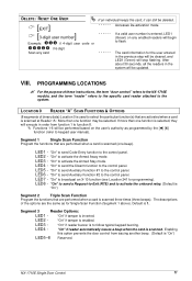
... system will be cleared, and LED1 (Green) will be updated. "On" to the control panel. "On" to send Auxiliary Function #1 to activate the Armed Stay mode. LED6 - "On" to function 8. The descriptions of these instructions, the term "door control" refers to the NX-1710E module, and the term "reader" refers to the specific card reader attached to keypad user manual). Default is entered, LED1 (Green) on the user's authority as for programming...
... system will be cleared, and LED1 (Green) will be updated. "On" to the control panel. "On" to send Auxiliary Function #1 to activate the Armed Stay mode. LED6 - "On" to function 8. The descriptions of these instructions, the term "door control" refers to the NX-1710E module, and the term "reader" refers to the specific card reader attached to keypad user manual). Default is entered, LED1 (Green) on the user's authority as for programming...
Installation Manual
Page 12
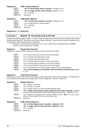
... is "On") LED2 - "On" to -Exit (RTE); The descriptions of system. (Default is scanned three times {three beeps}. "On" if reader buzzer is used to follow typical keypad buzzing. LED4-8 Reserved. 12 NX-1710E Single Door Control "On" to follow Ready status of binary data) Location 1 is to keypad user manual). LED4-8 Reserved. LED2 - Segment 4 LED1 (Green) Options: LED1 - LED4-8 Reserved. Default is enabled. "On" to select the...
... is "On") LED2 - "On" to -Exit (RTE); The descriptions of system. (Default is scanned three times {three beeps}. "On" if reader buzzer is used to follow typical keypad buzzing. LED4-8 Reserved. 12 NX-1710E Single Door Control "On" to follow Ready status of binary data) Location 1 is to keypad user manual). LED4-8 Reserved. LED2 - Segment 4 LED1 (Green) Options: LED1 - LED4-8 Reserved. Default is enabled. "On" to select the...
Installation Manual
Page 13
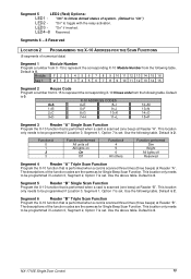
... set . NX-1710E Single Door Control 13 "On" to toggle with the relay activation. "On" to follow Armed status of the function codes are the same as for Single Beep Scan Function. LED4-8 Reserved. Module 1 2 3 4 5 6 7 8 9 10 11 12 13 14 15 16 Seg 1 0 1 2 3 4 5 6 7 8 9 10 11 12 13 14 15 Segment 2 House Code Program a number from 0-15 to be programmed if Location 0, Segment 2, Option 7 is "On") LED2 - Default...
... set . NX-1710E Single Door Control 13 "On" to toggle with the relay activation. "On" to follow Armed status of the function codes are the same as for Single Beep Scan Function. LED4-8 Reserved. Module 1 2 3 4 5 6 7 8 9 10 11 12 13 14 15 16 Seg 1 0 1 2 3 4 5 6 7 8 9 10 11 12 13 14 15 Segment 2 House Code Program a number from 0-15 to be programmed if Location 0, Segment 2, Option 7 is "On") LED2 - Default...
Installation Manual
Page 14
... door control is in Partition 1. (Default is enabled. 14 NX-1710E Single Door Control "On" if door control is in Partition 4. (Default is "On") LED7 - "On" if Weigand Format #6 is "On") LED6 - LED2 - LED5 - "On" if an RTE from a scanned card is not to be latched unlocked during an open schedule. LED5 - Segment 3 Enabling the Schedules for User Card Programming. "On" if driver follows Schedule 2. (Default...
... door control is in Partition 1. (Default is enabled. 14 NX-1710E Single Door Control "On" if door control is in Partition 4. (Default is "On") LED7 - "On" if Weigand Format #6 is "On") LED6 - LED2 - LED5 - "On" if an RTE from a scanned card is not to be latched unlocked during an open schedule. LED5 - Segment 3 Enabling the Schedules for User Card Programming. "On" if driver follows Schedule 2. (Default...
Installation Manual
Page 15
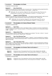
.... Segment 4 Door Fault Alarm Time Enter the amount of time a monitored zone (see Location 4, Segment 1) must be faulted before sending an alarm condition to the control panel. Segment 2 Request To Exit (RTE) Zone Program the zone that will be monitored as a door for Schedule 1. (Default is 0) NX-1710E Single Door Control 15 LOCATION 5 PROGRAMMING THE VARIOUS READER TIMERS (4 segment of numerical data) Segment 1 Scan Time Enter the amount of time required to hold a card between beeps to...
.... Segment 4 Door Fault Alarm Time Enter the amount of time a monitored zone (see Location 4, Segment 1) must be faulted before sending an alarm condition to the control panel. Segment 2 Request To Exit (RTE) Zone Program the zone that will be monitored as a door for Schedule 1. (Default is 0) NX-1710E Single Door Control 15 LOCATION 5 PROGRAMMING THE VARIOUS READER TIMERS (4 segment of numerical data) Segment 1 Scan Time Enter the amount of time required to hold a card between beeps to...
Installation Manual
Page 16
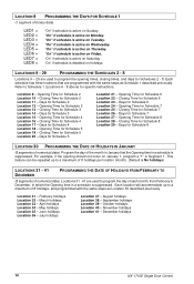
... used to December, in which the Opening time in January that are programmed with the same steps as Schedule 1 described previously. Refer to a maximum of binary data) LED1 = LED2 = LED3 = LED4 = LED5 = LED6 = LED7 = LED8 = "On" if schedule is active on Monday. December holidays 16 NX-1710E Single Door Control "On" if schedule is active on Thursday. Closing Time for specific instructions...
... used to December, in which the Opening time in January that are programmed with the same steps as Schedule 1 described previously. Refer to a maximum of binary data) LED1 = LED2 = LED3 = LED4 = LED5 = LED6 = LED7 = LED8 = "On" if schedule is active on Monday. December holidays 16 NX-1710E Single Door Control "On" if schedule is active on Thursday. Closing Time for specific instructions...
Installation Manual
Page 17
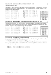
... card is to be logged as the partition. (Default is 0.) Segment 1 Segment 2 Code Entry Logging Partition for Reader "A" Code Entry Logging Partition for Reader "B" NX-1710E Single Door Control 17 Entering a 0 (zero) will send the entered value as Code Entry" is enabled (Location 3, Segment 1, Option 5). Each segment has 8 LEDs corresponding to the 8 possible user cards. If the LED is "on ", the card is active. LOCATION...
... card is to be logged as the partition. (Default is 0.) Segment 1 Segment 2 Code Entry Logging Partition for Reader "A" Code Entry Logging Partition for Reader "B" NX-1710E Single Door Control 17 Entering a 0 (zero) will send the entered value as Code Entry" is enabled (Location 3, Segment 1, Option 5). Each segment has 8 LEDs corresponding to the 8 possible user cards. If the LED is "on ", the card is active. LOCATION...
Installation Manual
Page 18
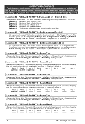
... first location used to program the Weigand Format 1. (Loc 45-57) Segment 1 Number of digits in Facility Code Segment 2 Number of digits in Badge Number Segment 3 Number of bits in Facility Code Segment 4 Number of bits in conjunction with Location 52 (Parity Type 3). Seg 5 -------- Seg 8 -------- Factory default is 1. Seg 3 -------- Seg 8 -------- 18 NX-1710E Single Door Control DIGITS & BITS (5 segments of decimal data) This is used in Badge Number Segment 5 Total number of format...
... first location used to program the Weigand Format 1. (Loc 45-57) Segment 1 Number of digits in Facility Code Segment 2 Number of digits in Badge Number Segment 3 Number of bits in Facility Code Segment 4 Number of bits in conjunction with Location 52 (Parity Type 3). Seg 5 -------- Seg 8 -------- Factory default is 1. Seg 3 -------- Seg 8 -------- 18 NX-1710E Single Door Control DIGITS & BITS (5 segments of decimal data) This is used in Badge Number Segment 5 Total number of format...
Installation Manual
Page 21
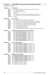
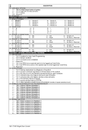
OPTIONS & DOOR CONTROL PARTITION 1 UNIT OPTIONS 1 = "On" if enabled for User Card Programming 2 = "On" if tamper enabled 3 = "On" if on-board zone is disabled 4 = Reserved. 5 = "On" if an RTE from a scanned card is to be logged as Code Entry 7-8 = Reserved 2 DOOR OPTIONS 1 = "On" if locking mechanism is a Maglock or Drop Bolt. 2 = "On" if access is allowed regardless of Armed status of regular operating hours...
OPTIONS & DOOR CONTROL PARTITION 1 UNIT OPTIONS 1 = "On" if enabled for User Card Programming 2 = "On" if tamper enabled 3 = "On" if on-board zone is disabled 4 = Reserved. 5 = "On" if an RTE from a scanned card is to be logged as Code Entry 7-8 = Reserved 2 DOOR OPTIONS 1 = "On" if locking mechanism is a Maglock or Drop Bolt. 2 = "On" if access is allowed regardless of Armed status of regular operating hours...
Installation Manual
Page 35
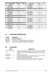
... Mask 4 -------- 8 LOCATION 147 - Triple Beep Triple Scan A zone can be programmed to Loc 0, Pg 11) To "present" or pass a card or FOB within sensing range of the card reader module. ORDERING INFORMATION PART # NX-1710E NX-1700E NX-848E-KIT NX-848-KIT NX-648-KIT DESCRIPTION Single Door Control Module Proximity Card Reader NX-8E Control, NX-148E LED Keypad, 40VA Transformer NX-8 Control, NX-148E LED Keypad, 40VA Transformer NX-6 Control, NX-148E LED Keypad, 40VA Transformer XI.
... Mask 4 -------- 8 LOCATION 147 - Triple Beep Triple Scan A zone can be programmed to Loc 0, Pg 11) To "present" or pass a card or FOB within sensing range of the card reader module. ORDERING INFORMATION PART # NX-1710E NX-1700E NX-848E-KIT NX-848-KIT NX-648-KIT DESCRIPTION Single Door Control Module Proximity Card Reader NX-8E Control, NX-148E LED Keypad, 40VA Transformer NX-8 Control, NX-148E LED Keypad, 40VA Transformer NX-6 Control, NX-148E LED Keypad, 40VA Transformer XI.


