
User Manual
Page 2
... Table of Content Item Checklist 4 WARNING 4 Chapter 1 Introduction 5 1.1 Features Summary 5 1.2 GA-7VCSV-RH Motherboard Components 8 Chapter 2 Hardware Installation Process 10 2-1: Installing Processor and CPU Haet Sink 10 Step 2-1-1: Installing CPU ...Connect ribbon cables, cabinet wires, and power supply 15 2-4-1 : I/O Back Panel Introduction 15 2-4-2 :Connectors & Jumper Setting Introduction 17 Chapter 3 BIOS Setup 26 Main ...28 Advanced Processor Options 31 Advanced 33 Memory Configuration ...34 PCI Configuration ...36 I/O Device Configuration 38 Advanced Chipset Control 42 ...
... Table of Content Item Checklist 4 WARNING 4 Chapter 1 Introduction 5 1.1 Features Summary 5 1.2 GA-7VCSV-RH Motherboard Components 8 Chapter 2 Hardware Installation Process 10 2-1: Installing Processor and CPU Haet Sink 10 Step 2-1-1: Installing CPU ...Connect ribbon cables, cabinet wires, and power supply 15 2-4-1 : I/O Back Panel Introduction 15 2-4-2 :Connectors & Jumper Setting Introduction 17 Chapter 3 BIOS Setup 26 Main ...28 Advanced Processor Options 31 Advanced 33 Memory Configuration ...34 PCI Configuration ...36 I/O Device Configuration 38 Advanced Chipset Control 42 ...

User Manual
Page 6
English GA-7VCSV-RH Motherboard On-Board Graphic On-Board LAN XGI Volari Z7 with 16MB DDR SDRAM Dual Broadcom® 5789 Gigabit Ethernet controllers Hardware Monitor BIOS Additional Features Winbond 83792G controller Enhanced features with CPU Vcore, VCC3 (3.3V), VCC5V, VBAT3V, CPU Motherboard Temperature System Voltage ...Detect CPU/System Fan Revolution Detect CPU shutdown when overheat Phoenix BIOS on 8Mb flash ROM PS/2 Mouse wake up from S1 under Windows Operating System COM Port wake up Supports S1, S4, S5 ...
English GA-7VCSV-RH Motherboard On-Board Graphic On-Board LAN XGI Volari Z7 with 16MB DDR SDRAM Dual Broadcom® 5789 Gigabit Ethernet controllers Hardware Monitor BIOS Additional Features Winbond 83792G controller Enhanced features with CPU Vcore, VCC3 (3.3V), VCC5V, VBAT3V, CPU Motherboard Temperature System Voltage ...Detect CPU/System Fan Revolution Detect CPU shutdown when overheat Phoenix BIOS on 8Mb flash ROM PS/2 Mouse wake up from S1 under Windows Operating System COM Port wake up Supports S1, S4, S5 ...
User Manual
Page 12
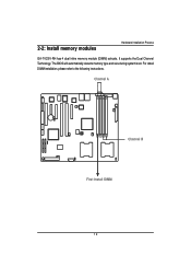
2-2: Install memory modules Hardware Installation Process GA-7VCSV-RH has 4 dual inline memory module (DIMM) sokcets. Channel A Channel B First Install DIMM 12 The BIOS will automatically detects memory type and size during system boot. It supports the Dual Channel Technology. For detail DIMM installation, please refer to the following instructions.
2-2: Install memory modules Hardware Installation Process GA-7VCSV-RH has 4 dual inline memory module (DIMM) sokcets. Channel A Channel B First Install DIMM 12 The BIOS will automatically detects memory type and size during system boot. It supports the Dual Channel Technology. For detail DIMM installation, please refer to the following instructions.
User Manual
Page 17
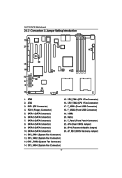
.... Battry 21. SATA 3 (SATA Connector) 8. SATA 6 (SATA Connector) 11. F_USB1 (Front USB Connector) 18. F_USB2 (Front USB Connector) 19. F_Panel (Front Panel Connector) 22. GA-7VCSV-RH Motherboard 2-4-2 :Connectors & Jumper Setting Introduction English 19 12 21 4 20 11 1 22 17 18 14 15 9 10 24 23 8 7 6 5 16 13 3 2 1. IDE1 (... 2 (SATA Connector) 7. SYS_FAN2 (System Fan Connector) 13. CPU_FAN2 (CPU 1 Fan Connector) 17. ATX2 2. SATA 1 (SATA Connector) 6. SATA 5 (SATA Connector) 10. JP_REC (BIOS Recovery Jumper) 17 ATX3 3. JP6 (Clear CMOS Jumper) 23.
.... Battry 21. SATA 3 (SATA Connector) 8. SATA 6 (SATA Connector) 11. F_USB1 (Front USB Connector) 18. F_USB2 (Front USB Connector) 19. F_Panel (Front Panel Connector) 22. GA-7VCSV-RH Motherboard 2-4-2 :Connectors & Jumper Setting Introduction English 19 12 21 4 20 11 1 22 17 18 14 15 9 10 24 23 8 7 6 5 16 13 3 2 1. IDE1 (... 2 (SATA Connector) 7. SYS_FAN2 (System Fan Connector) 13. CPU_FAN2 (CPU 1 Fan Connector) 17. ATX2 2. SATA 1 (SATA Connector) 6. SATA 5 (SATA Connector) 10. JP_REC (BIOS Recovery Jumper) 17 ATX3 3. JP6 (Clear CMOS Jumper) 23.
User Manual
Page 25
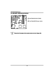
English GA-7VCSV-RH Motherboard 25 ) RECOVERY ( BIOS Recovery Function) Open: Disable this function. (Default) Short: Enable BIOS Recovery function Please short the jumper when system access recovery floppy disk. 25
English GA-7VCSV-RH Motherboard 25 ) RECOVERY ( BIOS Recovery Function) Open: Disable this function. (Default) Short: Enable BIOS Recovery function Please short the jumper when system access recovery floppy disk. 25
User Manual
Page 26
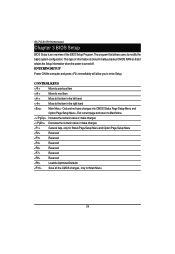
... Option Page Setup Menu Reserved Reserved Reserved Reserved Reserved Reserved Load the Optimized Defaults Save all the CMOS changes, only for Main Menu 26 GA-7VCSV-RH Motherboard Chapter 3 BIOS Setup BIOS Setup is stored in the right hand Main Menu - The program that it retains the Setup information when the power is turned off... allows users to modify the basic system configuration. Exit current page and return to enter Setup. This type of information is an overview of the BIOS Setup Program.
... Option Page Setup Menu Reserved Reserved Reserved Reserved Reserved Reserved Load the Optimized Defaults Save all the CMOS changes, only for Main Menu 26 GA-7VCSV-RH Motherboard Chapter 3 BIOS Setup BIOS Setup is stored in the right hand Main Menu - The program that it retains the Setup information when the power is turned off... allows users to modify the basic system configuration. Exit current page and return to enter Setup. This type of information is an overview of the BIOS Setup Program.
User Manual
Page 28
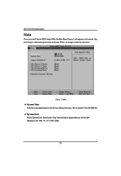
GA-7VCSV-RH Motherboard Main Once you set the date. (Weekend: DD: MM: YY) (YY: 1099~2099) 28 Use arrow keys to select among the items and press to accept or enter the sub-menu. Note that the "Day" automatically changed after you enter Phoenix BIOS Setup Utility, the Main Menu (Figure 1) will appear on the 24-hour military time clock. Set the System Time (HH:MM:SS) System Date Set the System Date. Figure 1: Main System Time The time is calculated based on the screen.
GA-7VCSV-RH Motherboard Main Once you set the date. (Weekend: DD: MM: YY) (YY: 1099~2099) 28 Use arrow keys to select among the items and press to accept or enter the sub-menu. Note that the "Day" automatically changed after you enter Phoenix BIOS Setup Utility, the Main Menu (Figure 1) will appear on the 24-hour military time clock. Set the System Time (HH:MM:SS) System Date Set the System Date. Figure 1: Main System Time The time is calculated based on the screen.
User Manual
Page 34
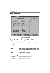
After rebooting system, the Memory Reset item will clear the memory error status. Memory Reset Yes No Select 'Yes', system will set to 'No' automatically. Disable this function. (Default value) Extend RAM Step Enabled Disabled Enable test extended memroy process. Disable this function. (Default value) 34 GA-7VCSV-RH Motherboard Memory Configuration Figure 2-1: Memory Configuration System Memory/Extended Memory/DIMMGroup 1~8 Status These category is display-only which is determined by POST (Power On Self Test) of the BIOS. Save the changes and restart system.
After rebooting system, the Memory Reset item will clear the memory error status. Memory Reset Yes No Select 'Yes', system will set to 'No' automatically. Disable this function. (Default value) Extend RAM Step Enabled Disabled Enable test extended memroy process. Disable this function. (Default value) 34 GA-7VCSV-RH Motherboard Memory Configuration Figure 2-1: Memory Configuration System Memory/Extended Memory/DIMMGroup 1~8 Status These category is display-only which is determined by POST (Power On Self Test) of the BIOS. Save the changes and restart system.

User Manual
Page 50
If any items require changes, please consult your system supervisor. 50 All items in this menu cannot be modified in user's mode. Including information of BIOS Version and GBIA Module Version. GA-7VCSV-RH Motherboard System Management Figure 4-1: System Management Server Management This category allows user to view the server management features.
If any items require changes, please consult your system supervisor. 50 All items in this menu cannot be modified in user's mode. Including information of BIOS Version and GBIA Module Version. GA-7VCSV-RH Motherboard System Management Figure 4-1: System Management Server Management This category allows user to view the server management features.
User Manual
Page 56
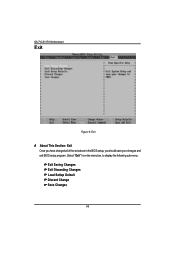
Exit Saving Changes Exit Discarding Changes Load Settup Default Discard Change Save Changes 56 GA-7VCSV-RH Motherboard Exit Figure 6: Exit * About This Section: Exit Once you have changed all of the set values in the BIOS setup, you should save your chnages and exit BIOS setup program. Select "Exit" from the menu bar, to display the following sub-menu.
Exit Saving Changes Exit Discarding Changes Load Settup Default Discard Change Save Changes 56 GA-7VCSV-RH Motherboard Exit Figure 6: Exit * About This Section: Exit Once you have changed all of the set values in the BIOS setup, you should save your chnages and exit BIOS setup program. Select "Exit" from the menu bar, to display the following sub-menu.

User Manual
Page 72
GA-7VCSV-RH Motherboard RCehvaispitoenr H6istAoprypendix Acronyms Acronyms Meaning ACPI Advanced Configuration and Power Interface APM Advanced Power Management AGP Accelerated Graphics Port AMR Audio Modem Riser ACR Advanced Communications Riser BBS BIOS Boot Specification BIOS Basic Input / Output System CPU Central Processing Unit CMOS Complementary Metal Oxide Semiconductor CRIMM Continuity RIMM CNR Communication and Networking...
GA-7VCSV-RH Motherboard RCehvaispitoenr H6istAoprypendix Acronyms Acronyms Meaning ACPI Advanced Configuration and Power Interface APM Advanced Power Management AGP Accelerated Graphics Port AMR Audio Modem Riser ACR Advanced Communications Riser BBS BIOS Boot Specification BIOS Basic Input / Output System CPU Central Processing Unit CMOS Complementary Metal Oxide Semiconductor CRIMM Continuity RIMM CNR Communication and Networking...


