
Manual
Page 1
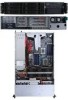
GIGABYTE GS-R22T61-RH/GS-R22T81-RH 2U Rack Mount Server Service Guide Dual Intel® Xeon LGA1366 Processor Serverboard Rev. 1.0
GIGABYTE GS-R22T61-RH/GS-R22T81-RH 2U Rack Mount Server Service Guide Dual Intel® Xeon LGA1366 Processor Serverboard Rev. 1.0
Manual
Page 3
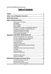
... Card Installation (GC-RFX2N-RH/Optional 20 GS-R22T81-RH Hard Disk Drive Installation 22 GS-R22T61-RH Hard Disk Drive Installation 23 FAN Duct Removal and Installation 24 Appearance of GS-R22T61-RH/GS-R22T81-RH 25 Front View of GS-R22T61-RH (For 3.5 HDDs solution 25 Front View of GS-R22T81-RH (For 2.5 HDDs solution 25 Rear View of GS-R22T61-RH/GS-R22T81-RH 26 Front Panel LED...
... Card Installation (GC-RFX2N-RH/Optional 20 GS-R22T81-RH Hard Disk Drive Installation 22 GS-R22T61-RH Hard Disk Drive Installation 23 FAN Duct Removal and Installation 24 Appearance of GS-R22T61-RH/GS-R22T81-RH 25 Front View of GS-R22T61-RH (For 3.5 HDDs solution 25 Front View of GS-R22T81-RH (For 2.5 HDDs solution 25 Rear View of GS-R22T61-RH/GS-R22T81-RH 26 Front Panel LED...
Manual
Page 5
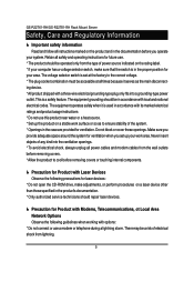
The equipment grounding should be in the case are provided for ventilation. Retain all power cables and modem cables from lightning. 5 GS-R22T61-RH/GS-R22T81-RH Rack Mount Server Safety, Care and Regulatory Information Important safety information Read and follow all instructions marked on the product and in the documentation ...
The equipment grounding should be in the case are provided for ventilation. Retain all power cables and modem cables from lightning. 5 GS-R22T61-RH/GS-R22T81-RH Rack Mount Server Safety, Care and Regulatory Information Important safety information Read and follow all instructions marked on the product and in the documentation ...
Manual
Page 7
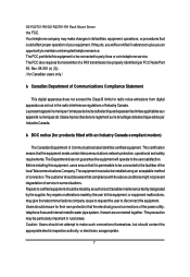
... and safety requirements. The FCC also requires the transmitter of a FAX transmission be installed using an acceptable method of Communications label identifies certified equipment. GS-R22T61-RH/GS-R22T81-RH Rack Mount Server the FCC. Le present appareil numerique n'emet pas de bruits radioelectriques depassant les limites applicables aux appareils numeriques de Classe A prescrites dans...
... and safety requirements. The FCC also requires the transmitter of a FAX transmission be installed using an acceptable method of Communications label identifies certified equipment. GS-R22T61-RH/GS-R22T81-RH Rack Mount Server the FCC. Le present appareil numerique n'emet pas de bruits radioelectriques depassant les limites applicables aux appareils numeriques de Classe A prescrites dans...
Manual
Page 9
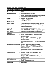
GS-R22T61-RH/GS-R22T81-RH Rack Mount Server System Specification Motherboard Processor Supported Chipset System Memory: Memory Capacity Memory Type DIMM Size ... Full height riser card: (Optional) Low-profile riser card: SATA RAID controller Cooling Fans: GA-7TTSH1-RH Supports dual Intel® Xeon® processors Intel Xeon® Dual-Core/Quad-Core processor in LGA 1366 socket Supports Intel Quickpath Interconnect up to...
GS-R22T61-RH/GS-R22T81-RH Rack Mount Server System Specification Motherboard Processor Supported Chipset System Memory: Memory Capacity Memory Type DIMM Size ... Full height riser card: (Optional) Low-profile riser card: SATA RAID controller Cooling Fans: GA-7TTSH1-RH Supports dual Intel® Xeon® processors Intel Xeon® Dual-Core/Quad-Core processor in LGA 1366 socket Supports Intel Quickpath Interconnect up to...
Manual
Page 11
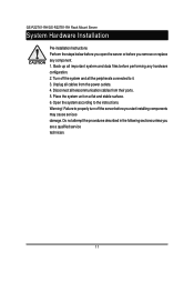
... telecommunication cables from the power outlets. 4. Disconnect all cables from their ports. 5. Turn off the server before you remove or replace any hardware configuration. 2. GS-R22T61-RH/GS-R22T81-RH Rack Mount Server System Hardware Installation Pre-installation Instructions Perform the steps below before you open the server or before you start installing components may...
... telecommunication cables from the power outlets. 4. Disconnect all cables from their ports. 5. Turn off the server before you remove or replace any hardware configuration. 2. GS-R22T61-RH/GS-R22T81-RH Rack Mount Server System Hardware Installation Pre-installation Instructions Perform the steps below before you open the server or before you start installing components may...
Manual
Page 13
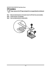
Step 1 Raise the metal locking lever on the socket. Step 3 Push the metal lever back into locked position. 1 2 3 13 GS-R22T61-RH/GS-R22T81-RH Rack Mount Server CPU Installation Please make sure the CPU type and speed that are supported by the motherboard. Step 2 The CPU only fits in one orientation. Insert the CPU with the correct orientation.
Step 1 Raise the metal locking lever on the socket. Step 3 Push the metal lever back into locked position. 1 2 3 13 GS-R22T61-RH/GS-R22T81-RH Rack Mount Server CPU Installation Please make sure the CPU type and speed that are supported by the motherboard. Step 2 The CPU only fits in one orientation. Insert the CPU with the correct orientation.
Manual
Page 15
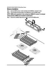
Close the plastic clip at both edges of the DIMM slots to remove the DIMM module. 2 1 2 DIMMF1 DIMME1 DIMMF2 DIMME2 DIMMD1 DIMMD2 CPU2 CPU1 DIMMA2 DIMMA1 DIMMB2 DIMMB1 DIMMC2 DIMMC1 15 NOTE! Reverse the installation steps when you wish to lock the DIMM module. Insert the DIMM memory module vertically into the DIMM slot, and push it down. DIMM must be populated in matched pairs. For dualquad channel operation, DIMMs must be installed in order starting from DIMMA1/D1 sockets. Step 3. Step 2. GS-R22T61-RH/GS-R22T81-RH Rack Mount Server Memory Installation Step 1.
Close the plastic clip at both edges of the DIMM slots to remove the DIMM module. 2 1 2 DIMMF1 DIMME1 DIMMF2 DIMME2 DIMMD1 DIMMD2 CPU2 CPU1 DIMMA2 DIMMA1 DIMMB2 DIMMB1 DIMMC2 DIMMC1 15 NOTE! Reverse the installation steps when you wish to lock the DIMM module. Insert the DIMM memory module vertically into the DIMM slot, and push it down. DIMM must be populated in matched pairs. For dualquad channel operation, DIMMs must be installed in order starting from DIMMA1/D1 sockets. Step 3. Step 2. GS-R22T61-RH/GS-R22T81-RH Rack Mount Server Memory Installation Step 1.
Manual
Page 17
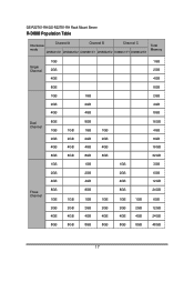
GS-R22T61-RH/GS-R22T81-RH Rack Mount Server R-DIMM Population Table Interleave Channel A Channel B Channel C mode DIMMA1/D1 DIMMA2/D2 DIMMB1/E1 DIMMB2/E2 DIMMC1/F1 DIMMC2/F2 Total Memory Single Channel 1GB 2GB 4GB 1GB 2GB 4GB 8GB 1GB 2GB 4GB 1GB 2GB 4GB 8GB 2GB 4GB 8GB Dual Channel Three Channel 8GB 1GB 2GB 4GB 8GB 1GB 2GB 4GB 8GB 1GB 2GB 4GB 8GB 1GB 2GB 4GB 8GB 1GB 2GB 4GB 8GB 8GB 1GB 2GB 4GB 8GB 1GB 2GB 4GB 8GB 1GB 2GB 4GB 8GB 1GB 2GB 4GB 8GB 1GB 2GB 4GB 8GB 1GB 2GB 4GB 8GB 1GB 2GB 4GB 8GB 1GB 2GB 4GB 8GB 16GB 4GB 8GB 16GB 32GB 3GB 6GB 12GB 24GB 6GB 12GB 24GB 48GB 17
GS-R22T61-RH/GS-R22T81-RH Rack Mount Server R-DIMM Population Table Interleave Channel A Channel B Channel C mode DIMMA1/D1 DIMMA2/D2 DIMMB1/E1 DIMMB2/E2 DIMMC1/F1 DIMMC2/F2 Total Memory Single Channel 1GB 2GB 4GB 1GB 2GB 4GB 8GB 1GB 2GB 4GB 1GB 2GB 4GB 8GB 2GB 4GB 8GB Dual Channel Three Channel 8GB 1GB 2GB 4GB 8GB 1GB 2GB 4GB 8GB 1GB 2GB 4GB 8GB 1GB 2GB 4GB 8GB 1GB 2GB 4GB 8GB 8GB 1GB 2GB 4GB 8GB 1GB 2GB 4GB 8GB 1GB 2GB 4GB 8GB 1GB 2GB 4GB 8GB 1GB 2GB 4GB 8GB 1GB 2GB 4GB 8GB 1GB 2GB 4GB 8GB 1GB 2GB 4GB 8GB 16GB 4GB 8GB 16GB 32GB 3GB 6GB 12GB 24GB 6GB 12GB 24GB 48GB 17

Manual
Page 18
Step 3 Lift the riser bracket slightly, then pull it out from the server chassis. Hardware Installation Process PCI Expansion Card Installation (GC-RLE2N-RH/GC-RFE2N-RH) Step 1 Loosen the riser bracket screws which attached on on the system. Step 4 Slide the expansion card into the slot until the card firmly seats. Step 5 Slide another expansion card into the slot until the card firmly seats. Step 2 Loosen the rest riser bracket bracket screws. Align the riser bracket to the system module. 2 21 2 1 3 18
Step 3 Lift the riser bracket slightly, then pull it out from the server chassis. Hardware Installation Process PCI Expansion Card Installation (GC-RLE2N-RH/GC-RFE2N-RH) Step 1 Loosen the riser bracket screws which attached on on the system. Step 4 Slide the expansion card into the slot until the card firmly seats. Step 5 Slide another expansion card into the slot until the card firmly seats. Step 2 Loosen the rest riser bracket bracket screws. Align the riser bracket to the system module. 2 21 2 1 3 18
Manual
Page 19
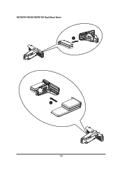
GS-R22T61-RH/GS-R22T81-RH Rack Mount Server 4 5 19
GS-R22T61-RH/GS-R22T81-RH Rack Mount Server 4 5 19
Manual
Page 20
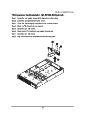
Secure the card with screws. Loosen the rest riser bracket bracket screws. Attach anothr PCI-E card to the system module until it out from the server chassis. Align the riser bracket to the riser bracket the other side. Lift the riser bracket slightly, then pull it firmly seats. 2 21 2 1 3 20 Secure the card with screws. Hardware Installation Process PCI Expansion Card Installation (GC-RFX2N-RH/Optional) Step 1 Step 2 Step 3 Step 4 Step 5 Step 6 Step 7 Step 8 Loosen the riser bracket screws which attached on on the system. Attach the PCI-E card to the riser bracket.
Secure the card with screws. Loosen the rest riser bracket bracket screws. Attach anothr PCI-E card to the system module until it out from the server chassis. Align the riser bracket to the riser bracket the other side. Lift the riser bracket slightly, then pull it firmly seats. 2 21 2 1 3 20 Secure the card with screws. Hardware Installation Process PCI Expansion Card Installation (GC-RFX2N-RH/Optional) Step 1 Step 2 Step 3 Step 4 Step 5 Step 6 Step 7 Step 8 Loosen the riser bracket screws which attached on on the system. Attach the PCI-E card to the riser bracket.
Manual
Page 21
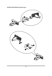
GS-R22T61-RH/GS-R22T81-RH Rack Mount Server 5 4 5 6 7 7 7 21
GS-R22T61-RH/GS-R22T81-RH Rack Mount Server 5 4 5 6 7 7 7 21
Manual
Page 22
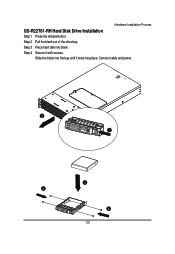
Slide the blank into the bay until it with screws. Step 4 Secure it locks into blank. Hardware Installation Process GS-R22T81-RH Hard Disk Drive Installation Step 1 Press the release button. Step 2 Pull the blank out of the drive bay. Connect cable and power. 2 1 3 4 4 22 Step 3 Place hard disk into place.
Slide the blank into the bay until it with screws. Step 4 Secure it locks into blank. Hardware Installation Process GS-R22T81-RH Hard Disk Drive Installation Step 1 Press the release button. Step 2 Pull the blank out of the drive bay. Connect cable and power. 2 1 3 4 4 22 Step 3 Place hard disk into place.
Manual
Page 23
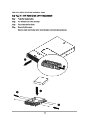
GS-R22T61-RH/GS-R22T81-RH Rack Mount Server GS-R22T61-RH Hard Disk Drive Installation Step 1 Step 2 Step 3 Step 4 Press the release button. Slide the blank into the bay until it with screws. Secure it locks into blank. Place hard disk into place. Connect cable and power. 2 1 4 3 4 23 Pull the blank out of the drive bay.
GS-R22T61-RH/GS-R22T81-RH Rack Mount Server GS-R22T61-RH Hard Disk Drive Installation Step 1 Step 2 Step 3 Step 4 Press the release button. Slide the blank into the bay until it with screws. Secure it locks into blank. Place hard disk into place. Connect cable and power. 2 1 4 3 4 23 Pull the blank out of the drive bay.
Manual
Page 25
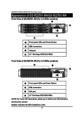
For Front LED description, please go to Switch and LED Indicators Introduction section. GS-R22T61-RH/GS-R22T81-RH Rack Mount Server Appearance of GS-R22T61-RH/GS-R22T81-RH Front View of GS-R22T61-RH (For 3.5 HDDs solution) 2 5 1 4 0 3 Front panel LEDs and Power Button USB connectors VGA port 3.5" Hot-Swap SATA/SAS HDDs Front View of GS-R22T81-RH (For 2.5 HDDs solution) 0 1 2 3 4 5 6 7 8 9 10 11 12 1314 15 Front panel LEDs and Power Button USB connectors VGA port 2.5" Hot-Swap SATA/SAS HDDs NOTE! Number indicates the HDD installation order. 25
For Front LED description, please go to Switch and LED Indicators Introduction section. GS-R22T61-RH/GS-R22T81-RH Rack Mount Server Appearance of GS-R22T61-RH/GS-R22T81-RH Front View of GS-R22T61-RH (For 3.5 HDDs solution) 2 5 1 4 0 3 Front panel LEDs and Power Button USB connectors VGA port 3.5" Hot-Swap SATA/SAS HDDs Front View of GS-R22T81-RH (For 2.5 HDDs solution) 0 1 2 3 4 5 6 7 8 9 10 11 12 1314 15 Front panel LEDs and Power Button USB connectors VGA port 2.5" Hot-Swap SATA/SAS HDDs NOTE! Number indicates the HDD installation order. 25
Manual
Page 26
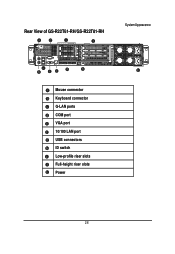
Rear View of GS-R22T61-RH/GS-R22T81-RH System Appearance Mouse connector Keyboard connector G-LAN ports COM port VGA port 10/100 LAN port USB connectors ID switch Low-profile riser slots Full-height riser slots Power 26
Rear View of GS-R22T61-RH/GS-R22T81-RH System Appearance Mouse connector Keyboard connector G-LAN ports COM port VGA port 10/100 LAN port USB connectors ID switch Low-profile riser slots Full-height riser slots Power 26

Manual
Page 27
GS-R22T61-RH/GS-R22T81-RH Rack Mount Server Front Panel LED Indicators No Indicator Color State 1 LAN1 Green On activity Green Blink 2 LAN2 Green On activity Green Blink 3 HDD Green ...
GS-R22T61-RH/GS-R22T81-RH Rack Mount Server Front Panel LED Indicators No Indicator Color State 1 LAN1 Green On activity Green Blink 2 LAN2 Green On activity Green Blink 3 HDD Green ...
Manual
Page 30
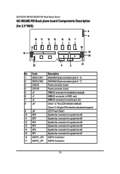
GS-R22T61-RH/GS-R22T81-RH Rack Mount Server GC-BS28E-RH Back plane board Components Description (for 2.5"HDD) 8 9 10 11 12 13 14 15 7 17 16 2 19 1 18 4 3 20 22 6 5 21 No Code Description 1 SAS/CON1 ...
GS-R22T61-RH/GS-R22T81-RH Rack Mount Server GC-BS28E-RH Back plane board Components Description (for 2.5"HDD) 8 9 10 11 12 13 14 15 7 17 16 2 19 1 18 4 3 20 22 6 5 21 No Code Description 1 SAS/CON1 ...

Manual
Page 32
GS-R22T61-RH/GS-R22T81-RH Rack Mount Server GC-BS26E-RH Back plane board Components Description (for 3.5"HDD) 15 14 13 12 11 10 18 17 16 7 23 24 25 26 4 2 5 8 3 6 9 20 19 No Code 1 J1 2 ...
GS-R22T61-RH/GS-R22T81-RH Rack Mount Server GC-BS26E-RH Back plane board Components Description (for 3.5"HDD) 15 14 13 12 11 10 18 17 16 7 23 24 25 26 4 2 5 8 3 6 9 20 19 No Code 1 J1 2 ...