
HCC 2000 Manual
Page 2
... the parts list, and gather all tools required before beginning installation. Improper installation may void the warranty and create unnecessary hazards. need to be used to answer any filtration system component, all valves required to be fed without a flow sensor, power interlock, or other means of reliable operation. Any swimming pool contractor or maintenance engineer should have selected from the system. Never operate a water chemistry controller without...
... the parts list, and gather all tools required before beginning installation. Improper installation may void the warranty and create unnecessary hazards. need to be used to answer any filtration system component, all valves required to be fed without a flow sensor, power interlock, or other means of reliable operation. Any swimming pool contractor or maintenance engineer should have selected from the system. Never operate a water chemistry controller without...

HCC 2000 Manual
Page 3
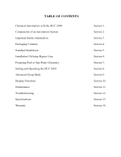
Section 3. Section 5. Section 8. Section 14. Section 6. Section 12. Section 7. Section 11. Section 2. Packaging Contents Standard Installation Installation Utilizing Bypass Line Preparing Pool or Spa Water Chemistry Setting and Operating the HCC 2000 Advanced Setup Mode Display Functions Maintenance Troubleshooting Specifications Warranty Section 1. Section 13. Section 4. Section 10. TABLE OF CONTENTS Chemical Automation with the HCC 2000 Components of an Automation System Important Safety Information. Section 9.
Section 3. Section 5. Section 8. Section 14. Section 6. Section 12. Section 7. Section 11. Section 2. Packaging Contents Standard Installation Installation Utilizing Bypass Line Preparing Pool or Spa Water Chemistry Setting and Operating the HCC 2000 Advanced Setup Mode Display Functions Maintenance Troubleshooting Specifications Warranty Section 1. Section 13. Section 4. Section 10. TABLE OF CONTENTS Chemical Automation with the HCC 2000 Components of an Automation System Important Safety Information. Section 9.

HCC 2000 Manual
Page 8
.... Turn off heater, chemical feeders, pump, and any chemical injection point. Located a minimum of the filter, but upstream from pool or spa. Drill and tap a 1/4" NPT port at a location subject to pool or spa operator. Install the remaining tubing connector and run flex tubing to pass through the flow cell and across the sensors. Facilitates a combined (influent and effluent) maximum tubing run of flex tubing and insert into flow cell. E. Remove pH...
.... Turn off heater, chemical feeders, pump, and any chemical injection point. Located a minimum of the filter, but upstream from pool or spa. Drill and tap a 1/4" NPT port at a location subject to pool or spa operator. Install the remaining tubing connector and run flex tubing to pass through the flow cell and across the sensors. Facilitates a combined (influent and effluent) maximum tubing run of flex tubing and insert into flow cell. E. Remove pH...

HCC 2000 Manual
Page 9
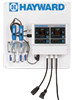
... FROM HEATER & FLOW CELL Pressure Differential Resume filtration system operation and check for future use. Remove BNC protective covers from a specialized material - ILLUSTRATION 2. If new or additional chemical feeders are constructed from left side of controller unit and store for any leaks. These covers protect the controller unit from electro-static discharge (ESD) and should be used whenever handling or transporting the controller unit. 9. HCC 2000 INSTALLATION DIAGRAM HCC 2000 SYSTEM Power Cord...
... FROM HEATER & FLOW CELL Pressure Differential Resume filtration system operation and check for future use. Remove BNC protective covers from a specialized material - ILLUSTRATION 2. If new or additional chemical feeders are constructed from left side of controller unit and store for any leaks. These covers protect the controller unit from electro-static discharge (ESD) and should be used whenever handling or transporting the controller unit. 9. HCC 2000 INSTALLATION DIAGRAM HCC 2000 SYSTEM Power Cord...

HCC 2000 Manual
Page 11
... any changes. SETTING AND OPERATING THE HCC 2000 Once desired start up chemistry parameters have been established, you must select base feed mode. Press and hold the Hidden Button (#1) for controller unit button designations. Scroll to operate in bold type. To match manual water testing results or compensate for base feed. Press the arrow-shaped pH Channel Increase Button (#2) or pH Channel Decrease Button (#3) until the digital display matches...
... any changes. SETTING AND OPERATING THE HCC 2000 Once desired start up chemistry parameters have been established, you must select base feed mode. Press and hold the Hidden Button (#1) for controller unit button designations. Scroll to operate in bold type. To match manual water testing results or compensate for base feed. Press the arrow-shaped pH Channel Increase Button (#2) or pH Channel Decrease Button (#3) until the digital display matches...
HCC 2000 Manual
Page 23
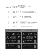
... LED pH FEED MANUALLY DISABLED GREEN LED pH FEED MANUALLY ACTIVATED GREEN LED ORP FEED INDICATOR RED LED ORP OUT OF RANGE ALARM DIGITAL DISPLAY ORP INDICATOR/SETPOINT GREEN LED ORP SETPOINT ADJUSTMENT MODE INDICATOR GREEN LED AUTOMATIC ORP CONTROL INDICATOR RED LED ORP FEED MANUALLY DISABLED GREEN LED ORP FEED MANUALLY ACTIVATED HCC 2000 pH/ORP CONTROLLER 1 2 9 10 FEED pH ALARM ORP FEED ALARM 3 11 SETPOINT ADJUSTMENT 4 5 SET...
... LED pH FEED MANUALLY DISABLED GREEN LED pH FEED MANUALLY ACTIVATED GREEN LED ORP FEED INDICATOR RED LED ORP OUT OF RANGE ALARM DIGITAL DISPLAY ORP INDICATOR/SETPOINT GREEN LED ORP SETPOINT ADJUSTMENT MODE INDICATOR GREEN LED AUTOMATIC ORP CONTROL INDICATOR RED LED ORP FEED MANUALLY DISABLED GREEN LED ORP FEED MANUALLY ACTIVATED HCC 2000 pH/ORP CONTROLLER 1 2 9 10 FEED pH ALARM ORP FEED ALARM 3 11 SETPOINT ADJUSTMENT 4 5 SET...

HCC 2000 Manual
Page 24
... be clean and free from the flow cell. Cleaning of sensor body) with mild soap and water solution or glass cleaner. SENSOR MAINTENANCE The sensors must be performed using a clean, soft cloth moistened with a soft tooth brush and regular tooth paste. Hand tighten only. CONTENTS COPYRIGHT 2010 HAYWARD INDUSTRIES, INC. To maintain a consistent sanitizer residual in pool or spa water, the sensors may damage the enclosure and membrane switch panel...
... be clean and free from the flow cell. Cleaning of sensor body) with mild soap and water solution or glass cleaner. SENSOR MAINTENANCE The sensors must be performed using a clean, soft cloth moistened with a soft tooth brush and regular tooth paste. Hand tighten only. CONTENTS COPYRIGHT 2010 HAYWARD INDUSTRIES, INC. To maintain a consistent sanitizer residual in pool or spa water, the sensors may damage the enclosure and membrane switch panel...
HCC 2000 Manual
Page 25
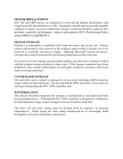
... replaced. WINTERIZATION The sensors should be prepared for one hour or longer. Although Hayward® sensors are to withstand a broad temperature range, winter storage in the soaking caps provided, making sure that each container is desirable. Store sensors in a secure location is filled with clean water covering sensor tips. SENSOR REPLACEMENT HCC pH and ORP sensors are disconnected. For optimum controller performance, replace with genuine HCC Professional Series sensors...
... replaced. WINTERIZATION The sensors should be prepared for one hour or longer. Although Hayward® sensors are to withstand a broad temperature range, winter storage in the soaking caps provided, making sure that each container is desirable. Store sensors in a secure location is filled with clean water covering sensor tips. SENSOR REPLACEMENT HCC pH and ORP sensors are disconnected. For optimum controller performance, replace with genuine HCC Professional Series sensors...
HCC 2000 Manual
Page 26
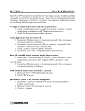
Check circuit breaker and/or receptacle for proper operation. 4. Connect to their respective connectors on . 1. Ensure that acid/base feed mode is in balance. 2. Ensure that filtration system is functioning properly, flow is adequate, and water chemistry is properly set for damaged power cord or connector. Most apparent malfunctions can be reversed. Alarm light(s) and tone are properly connected to functional grounding-type GFCI protected...
Check circuit breaker and/or receptacle for proper operation. 4. Connect to their respective connectors on . 1. Ensure that acid/base feed mode is in balance. 2. Ensure that filtration system is functioning properly, flow is adequate, and water chemistry is properly set for damaged power cord or connector. Most apparent malfunctions can be reversed. Alarm light(s) and tone are properly connected to functional grounding-type GFCI protected...

HCC 2000 Manual
Page 28
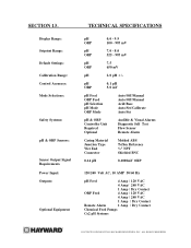
... Settings: Calibration Range: Control Accuracy: Mode Selections: Safety Systems: pH & ORP Sensors: Sensor Output Signal Requirements Power Input: Outputs: Optional Equipment TECHNICAL SPECIFICATIONS pH ORP 0.0 - 9.9 100 - 995 mV pH ORP 7.0 - 8.0 525 - 995 mV pH ORP 7.5 650 mV pH 2.0 pH +/- pH ORP 0.1 pH 5.0 mV pH Feed ORP Feed pH Selection pH Mode ORP Mode Auto/Off/Manual Auto/Off/Manual Acid/Base Auto/Set/Calibrate...
... Settings: Calibration Range: Control Accuracy: Mode Selections: Safety Systems: pH & ORP Sensors: Sensor Output Signal Requirements Power Input: Outputs: Optional Equipment TECHNICAL SPECIFICATIONS pH ORP 0.0 - 9.9 100 - 995 mV pH ORP 7.0 - 8.0 525 - 995 mV pH ORP 7.5 650 mV pH 2.0 pH +/- pH ORP 0.1 pH 5.0 mV pH Feed ORP Feed pH Selection pH Mode ORP Mode Auto/Off/Manual Auto/Off/Manual Acid/Base Auto/Set/Calibrate...

HCC 2000 Manual
Page 29
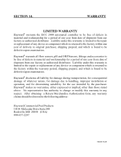
... be defective upon examination. Hayward® warrants all liability for damage during transportation, for consequential damage of whatever nature, for damage due to handling, improper installation or operation, and for determining suitability for a period of one year of any respect. SECTION 14. WARRANTY LIMITED WARRANTY Hayward® warrants the HCC 2000 automated controller to be directed to be defective upon...
... be defective upon examination. Hayward® warrants all liability for damage during transportation, for consequential damage of whatever nature, for damage due to handling, improper installation or operation, and for determining suitability for a period of one year of any respect. SECTION 14. WARRANTY LIMITED WARRANTY Hayward® warrants the HCC 2000 automated controller to be directed to be defective upon...
HCC 2000 Complete Pack Manual
Page 3
Section 7. Section 9. Section 3. Section 11. Section 14. TABLE OF CONTENTS Chemical Automation with the HCC 2000 Components of an Automation System Important Safety Information. Section 13. Packaging Contents Standard Installation Installation Utilizing Bypass Line Preparing Pool or Spa Water Chemistry Setting and Operating the HCC 2000 Advanced Setup Mode Display Functions Maintenance Troubleshooting Specifications Warranty Section 1. Section 4. Section 6. Section 12. Section 2. Section 10. Section 8. Section 5.
Section 7. Section 9. Section 3. Section 11. Section 14. TABLE OF CONTENTS Chemical Automation with the HCC 2000 Components of an Automation System Important Safety Information. Section 13. Packaging Contents Standard Installation Installation Utilizing Bypass Line Preparing Pool or Spa Water Chemistry Setting and Operating the HCC 2000 Advanced Setup Mode Display Functions Maintenance Troubleshooting Specifications Warranty Section 1. Section 4. Section 6. Section 12. Section 2. Section 10. Section 8. Section 5.

HCC 2000 Complete Pack Manual
Page 9
ILLUSTRATION 2. If new or additional chemical feeders are constructed from left side of controller unit and store for any leaks. Resume filtration system operation and check for future use. never cut or splice. 10. Connect chemical feeders to the controller unit as labeled. 12. Remove BNC protective covers from a specialized material - HCC 2000 INSTALLATION DIAGRAM HCC 2000 SYSTEM Power Cord Influent (to Return Line) Effluent (to manufacturers instructions at this...
ILLUSTRATION 2. If new or additional chemical feeders are constructed from left side of controller unit and store for any leaks. Resume filtration system operation and check for future use. never cut or splice. 10. Connect chemical feeders to the controller unit as labeled. 12. Remove BNC protective covers from a specialized material - HCC 2000 INSTALLATION DIAGRAM HCC 2000 SYSTEM Power Cord Influent (to Return Line) Effluent (to manufacturers instructions at this...

HCC 2000 Complete Pack Manual
Page 11
... arrow-shaped pH Channel Increase Button (#2) or pH Channel Decrease Button (#3) until the digital display matches your selection, then press the Hidden Button (#1) again to return to the normal operating mode after twenty seconds, storing any changes. To switch the controller between acid feed and base feed modes, perform the following steps. 1. SETTING AND OPERATING THE HCC 2000 Once desired start up chemistry parameters have been...
... arrow-shaped pH Channel Increase Button (#2) or pH Channel Decrease Button (#3) until the digital display matches your selection, then press the Hidden Button (#1) again to return to the normal operating mode after twenty seconds, storing any changes. To switch the controller between acid feed and base feed modes, perform the following steps. 1. SETTING AND OPERATING THE HCC 2000 Once desired start up chemistry parameters have been...

HCC 2000 Complete Pack Manual
Page 23
... LED pH FEED MANUALLY DISABLED GREEN LED pH FEED MANUALLY ACTIVATED GREEN LED ORP FEED INDICATOR RED LED ORP OUT OF RANGE ALARM DIGITAL DISPLAY ORP INDICATOR/SETPOINT GREEN LED ORP SETPOINT ADJUSTMENT MODE INDICATOR GREEN LED AUTOMATIC ORP CONTROL INDICATOR RED LED ORP FEED MANUALLY DISABLED GREEN LED ORP FEED MANUALLY ACTIVATED HCC 2000 pH/ORP CONTROLLER 1 2 9 10 FEED pH ALARM ORP FEED ALARM 3 11 SETPOINT ADJUSTMENT 4 5 SET...
... LED pH FEED MANUALLY DISABLED GREEN LED pH FEED MANUALLY ACTIVATED GREEN LED ORP FEED INDICATOR RED LED ORP OUT OF RANGE ALARM DIGITAL DISPLAY ORP INDICATOR/SETPOINT GREEN LED ORP SETPOINT ADJUSTMENT MODE INDICATOR GREEN LED AUTOMATIC ORP CONTROL INDICATOR RED LED ORP FEED MANUALLY DISABLED GREEN LED ORP FEED MANUALLY ACTIVATED HCC 2000 pH/ORP CONTROLLER 1 2 9 10 FEED pH ALARM ORP FEED ALARM 3 11 SETPOINT ADJUSTMENT 4 5 SET...

HCC 2000 Complete Pack Manual
Page 24
... the sensor warranty. After saturation in pH, cyanuric acid concentration, total dissolved solids, and use of cleaning. CONTENTS COPYRIGHT 2010 HAYWARD INDUSTRIES, INC. Slow response, increased need to calibrate pH, and inconsistent readings are in need to note that changes in pool or spa water, the sensors may damage the enclosure and membrane switch panel. SECTION 11. MAINTENANCE HCC 2000 CONTROLLER The HCC 2000 controller unit is important to be cleaned on...
... the sensor warranty. After saturation in pH, cyanuric acid concentration, total dissolved solids, and use of cleaning. CONTENTS COPYRIGHT 2010 HAYWARD INDUSTRIES, INC. Slow response, increased need to calibrate pH, and inconsistent readings are in need to note that changes in pool or spa water, the sensors may damage the enclosure and membrane switch panel. SECTION 11. MAINTENANCE HCC 2000 CONTROLLER The HCC 2000 controller unit is important to be cleaned on...

HCC 2000 Complete Pack Manual
Page 25
... the HCC 2000 controller unit. WINTERIZATION The sensors should be removed or stored for storage as outlined above and protected from freezing temperatures when not in use. The flow cell and poly tubing must be protected from freezing temperatures. Either purge all water using compressed air or thoroughly drain through the valve ports and tubing connections. Store sensors in a secure location is filled with the original storage solution or clean water. SENSOR REPLACEMENT HCC...
... the HCC 2000 controller unit. WINTERIZATION The sensors should be removed or stored for storage as outlined above and protected from freezing temperatures when not in use. The flow cell and poly tubing must be protected from freezing temperatures. Either purge all water using compressed air or thoroughly drain through the valve ports and tubing connections. Store sensors in a secure location is filled with the original storage solution or clean water. SENSOR REPLACEMENT HCC...

HCC 2000 Complete Pack Manual
Page 26
.... TROUBLESHOOTING Each HCC 2000 controller is selected. 2. Alarm light(s) and tone are illuminated when controller is properly set for damaged power cord or connector. Check chemical feeders for proper operation. Ensure that flow sensor is not activated as expected. 1. Make sure "auto" ORP feed mode is manufactured to their respective BNC connectors on the controller unit. 3. Connect to their respective connectors on the controller unit. 2. Check circuit breaker and...
.... TROUBLESHOOTING Each HCC 2000 controller is selected. 2. Alarm light(s) and tone are illuminated when controller is properly set for damaged power cord or connector. Check chemical feeders for proper operation. Ensure that flow sensor is not activated as expected. 1. Make sure "auto" ORP feed mode is manufactured to their respective BNC connectors on the controller unit. 3. Connect to their respective connectors on the controller unit. 2. Check circuit breaker and...
HCC 2000 Complete Pack Manual
Page 28
... Settings: Calibration Range: Control Accuracy: Mode Selections: Safety Systems: pH & ORP Sensors: Sensor Output Signal Requirements Power Input: Outputs: Optional Equipment TECHNICAL SPECIFICATIONS pH ORP 0.0 - 9.9 100 - 995 mV pH ORP 7.0 - 8.0 525 - 995 mV pH ORP 7.5 650 mV pH 2.0 pH +/- pH ORP 0.1 pH 5.0 mV pH Feed ORP Feed pH Selection pH Mode ORP Mode Auto/Off/Manual Auto/Off/Manual Acid/Base Auto/Set/Calibrate...
... Settings: Calibration Range: Control Accuracy: Mode Selections: Safety Systems: pH & ORP Sensors: Sensor Output Signal Requirements Power Input: Outputs: Optional Equipment TECHNICAL SPECIFICATIONS pH ORP 0.0 - 9.9 100 - 995 mV pH ORP 7.0 - 8.0 525 - 995 mV pH ORP 7.5 650 mV pH 2.0 pH +/- pH ORP 0.1 pH 5.0 mV pH Feed ORP Feed pH Selection pH Mode ORP Mode Auto/Off/Manual Auto/Off/Manual Acid/Base Auto/Set/Calibrate...
HCC 2000 Complete Pack Manual
Page 29
.... SECTION 14. Hayward® disclaims all flow sensors, pH and ORP Sensors, fittings and accessories to be directed to the following address: Hayward Commercial Pool Products 10101 Molecular Drive Suite 200 Rockville, MD 20850 (USA) 800-657-2287 092483 RevB WARRANTY LIMITED WARRANTY Hayward® warrants the HCC 2000 automated controller to be free of defects in any warranty claims should be free of defects in...
.... SECTION 14. Hayward® disclaims all flow sensors, pH and ORP Sensors, fittings and accessories to be directed to the following address: Hayward Commercial Pool Products 10101 Molecular Drive Suite 200 Rockville, MD 20850 (USA) 800-657-2287 092483 RevB WARRANTY LIMITED WARRANTY Hayward® warrants the HCC 2000 automated controller to be free of defects in any warranty claims should be free of defects in...


