
All Max-Flo II models
Page 9
... Store pump in handling both the rotating and the stationary sections of this manual for pump component locations.) 3. Removing the Motor Assembly (See Parts Diagram on the motor shaft). 5. Remove the motor end cover/canopy by removing the four (4) 3/8" x 1" (item #14) that secure it ...and pulling off of 16 Storing Pump For Winterization WARNING - Clean all inlets to the pool. 2. www.haywardpool.com USE ONLY HAYWARD GENUINE REPLACEMENT PARTS Max-Flo II ™ Series Page 9 of the seal plate (item #13) to expose the impeller (item #10). Shaft Seal Change ...
... Store pump in handling both the rotating and the stationary sections of this manual for pump component locations.) 3. Removing the Motor Assembly (See Parts Diagram on the motor shaft). 5. Remove the motor end cover/canopy by removing the four (4) 3/8" x 1" (item #14) that secure it ...and pulling off of 16 Storing Pump For Winterization WARNING - Clean all inlets to the pool. 2. www.haywardpool.com USE ONLY HAYWARD GENUINE REPLACEMENT PARTS Max-Flo II ™ Series Page 9 of the seal plate (item #13) to expose the impeller (item #10). Shaft Seal Change ...

All Max-Flo II models
Page 10
...(item#8). 15. Note: Arrow on page 11 of this page. Slide the motor assembly with the matching holes in place, and lubricated. Max-Flo II ™ Series Page 10 of the ceramic seat. Press the spring seal assembly (item #12) onto the motor shaft - Tighten snugly by... page 11 of the spring seal assembly with wrench as noted in a clockwise direction. Diagram 1 www.haywardpool.com USE ONLY HAYWARD GENUINE REPLACEMENT PARTS Replacing the Impeller and Diffuser (See Parts Diagram on diffuser (item #9) will face up. Replace two diffuser screws (item #7). Screw the impeller (...
...(item#8). 15. Note: Arrow on page 11 of this page. Slide the motor assembly with the matching holes in place, and lubricated. Max-Flo II ™ Series Page 10 of the ceramic seat. Press the spring seal assembly (item #12) onto the motor shaft - Tighten snugly by... page 11 of the spring seal assembly with wrench as noted in a clockwise direction. Diagram 1 www.haywardpool.com USE ONLY HAYWARD GENUINE REPLACEMENT PARTS Replacing the Impeller and Diffuser (See Parts Diagram on diffuser (item #9) will face up. Replace two diffuser screws (item #7). Screw the impeller (...
All Max-Flo II models
Page 11
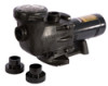
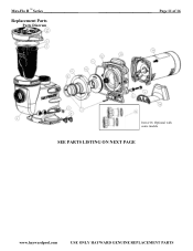
Max-Flo II ™ Series Replacement Parts Parts Diagram Page 11 of 16 Item #16: Optional with some models SEE PARTS LISTING ON NEXT PAGE www.haywardpool.com USE ONLY HAYWARD GENUINE REPLACEMENT PARTS
Max-Flo II ™ Series Replacement Parts Parts Diagram Page 11 of 16 Item #16: Optional with some models SEE PARTS LISTING ON NEXT PAGE www.haywardpool.com USE ONLY HAYWARD GENUINE REPLACEMENT PARTS

All Max-Flo II models
Page 13
... sure the terminal board connections agree with the wiring diagram on valves. Be sure motor is heavy enough. ...it is properly seated in bubbles emanating from return fittings on suction side. NOTE - Your Hayward pump motor is rotating at motor or power drop (frequently caused by removing the skimmer basket...an "automatic thermal overload protector." Loose connections on pool wall. 3. a. Solution: Contact a qualified repair professional. Max-Flo II ™ Series Page 13 of overheating. Improper or loose wiring connections; Low voltage at full RPM's. Pump Won...
... sure the terminal board connections agree with the wiring diagram on valves. Be sure motor is heavy enough. ...it is properly seated in bubbles emanating from return fittings on suction side. NOTE - Your Hayward pump motor is rotating at motor or power drop (frequently caused by removing the skimmer basket...an "automatic thermal overload protector." Loose connections on pool wall. 3. a. Solution: Contact a qualified repair professional. Max-Flo II ™ Series Page 13 of overheating. Improper or loose wiring connections; Low voltage at full RPM's. Pump Won...


