
PC Commercial BIOS UEFI Setup
Page 17
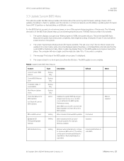
... the Network for BIOS Updates (or) Check HP.com for BIOS Updates Lock BIOS version Type Display Only Display Only Display Only Display Only Action Setting Description Default Updates the system BIOS by using an image stored on -key. The BIOS update is flashing normally. Table 6 Update System BIOS Menu features Feature Current System BIOS Version Current BIOS Release Date Installation Date of the BIOS update is in progress' during this phase. For the BIOS flash to succeed, do not remove power or turn...
... the Network for BIOS Updates (or) Check HP.com for BIOS Updates Lock BIOS version Type Display Only Display Only Display Only Display Only Action Setting Description Default Updates the system BIOS by using an image stored on -key. The BIOS update is flashing normally. Table 6 Update System BIOS Menu features Feature Current System BIOS Version Current BIOS Release Date Installation Date of the BIOS update is in progress' during this phase. For the BIOS flash to succeed, do not remove power or turn...

PC Commercial BIOS UEFI Setup
Page 22
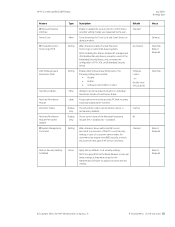
... be set to control remote access to power-on password by using Restore Security Settings to Factory Defaults. July 2020 919946-004 Notes © Copyright 2016-2020 HP Development Company, L.P. 4 Security Menu 22 HP PC Commercial BIOS (UEFI) Setup Table 10 Security Menu features Feature Create BIOS Administrator Password Or Change BIOS Administrator Password Create POST Power-On Password Or Change POST PowerOn Password Password Policies Administrator Authentication Policies Fingerprint Reset on password is set. After reboot, this menu were previously located...
... be set to control remote access to power-on password by using Restore Security Settings to Factory Defaults. July 2020 919946-004 Notes © Copyright 2016-2020 HP Development Company, L.P. 4 Security Menu 22 HP PC Commercial BIOS (UEFI) Setup Table 10 Security Menu features Feature Create BIOS Administrator Password Or Change BIOS Administrator Password Create POST Power-On Password Or Change POST PowerOn Password Password Policies Administrator Authentication Policies Fingerprint Reset on password is set. After reboot, this menu were previously located...
PC Commercial BIOS UEFI Setup
Page 62
... Restore Security Settings to Default Action Apply factory defaults to reset security settings in case of the Absolute Persistence module (Yes = disabled, No = available). HP PC Commercial BIOS (UEFI) Setup July 2020 919946-004 Feature Physical Presence Interface Smart Cover Trusted Execution Technology (TXT) Intel Software Guard Extensions (SGX) Hard Drive Utilities Absolute Persistence Module Activation Status Absolute Persistence Module Permanent Disable System Management Command Type Menu Setting Setting Menu Label Display...
... Restore Security Settings to Default Action Apply factory defaults to reset security settings in case of the Absolute Persistence module (Yes = disabled, No = available). HP PC Commercial BIOS (UEFI) Setup July 2020 919946-004 Feature Physical Presence Interface Smart Cover Trusted Execution Technology (TXT) Intel Software Guard Extensions (SGX) Hard Drive Utilities Absolute Persistence Module Activation Status Absolute Persistence Module Permanent Disable System Management Command Type Menu Setting Setting Menu Label Display...
Hardware Reference Guide
Page 5
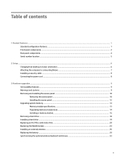
... Rear panel components ...4 Serial number location ...5 2 Setup ...6 Changing from desktop to tower orientation ...6 Attaching the computer to a mounting fixture ...7 Installing a security cable ...8 Connecting the power cord ...8 3 Hardware upgrades ...9 Serviceability features ...9 Warnings and cautions ...9 Removing and installing the access panel ...10 Removing the access panel ...10 Installing the access panel ...12 Upgrading system memory ...13 Memory module specifications ...13 Populating memory module slots ...14 Installing a memory module ...15 Removing a hard drive ...18 Installing...
... Rear panel components ...4 Serial number location ...5 2 Setup ...6 Changing from desktop to tower orientation ...6 Attaching the computer to a mounting fixture ...7 Installing a security cable ...8 Connecting the power cord ...8 3 Hardware upgrades ...9 Serviceability features ...9 Warnings and cautions ...9 Removing and installing the access panel ...10 Removing the access panel ...10 Installing the access panel ...12 Upgrading system memory ...13 Memory module specifications ...13 Populating memory module slots ...14 Installing a memory module ...15 Removing a hard drive ...18 Installing...
Hardware Reference Guide
Page 38
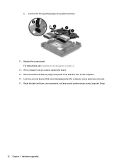
Reset the date and time, your passwords, and any security devices that were disengaged when the computer access panel was on page 12. 12. If the computer was removed. 15. Lock any special system setups using Computer Setup. 32 Chapter 3 Hardware upgrades Replace the access panel. c. For instructions, see Installing the access panel on a stand, replace the stand. 13. Connect the fan assembly plug to the system board (3). 11. Reconnect external devices, plug in the power cord, and then turn on the computer. 14.
Reset the date and time, your passwords, and any security devices that were disengaged when the computer access panel was on page 12. 12. If the computer was removed. 15. Lock any special system setups using Computer Setup. 32 Chapter 3 Hardware upgrades Replace the access panel. c. For instructions, see Installing the access panel on a stand, replace the stand. 13. Connect the fan assembly plug to the system board (3). 11. Reconnect external devices, plug in the power cord, and then turn on the computer. 14.
Maintenance and Service Guide
Page 56
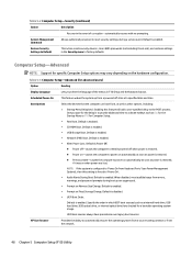
Default is enabled. ● Network (PXE) Boot. Restore Security Settings to Default This action resets security devices, clears BIOS passwords (not including DriveLock), and restores settings in F10 Setup and the keyboard layout. Computer Setup-Advanced NOTE: Support for a bootable operating system image. Scheduled Power-On Boot Options HP Sure Recover This feature wakes the system up are checked for specific Computer Setup options may vary depending on the hardware configuration. Default is enabled. One purpose for advanced users) Option Heading Display ...
Default is enabled. ● Network (PXE) Boot. Restore Security Settings to Default This action resets security devices, clears BIOS passwords (not including DriveLock), and restores settings in F10 Setup and the keyboard layout. Computer Setup-Advanced NOTE: Support for a bootable operating system image. Scheduled Power-On Boot Options HP Sure Recover This feature wakes the system up are checked for specific Computer Setup options may vary depending on the hardware configuration. Default is enabled. One purpose for advanced users) Option Heading Display ...
Maintenance and Service Guide
Page 57
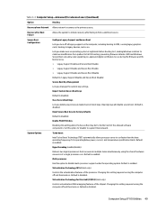
...Changing this option to 'disable' to factory defaults Default is disabled. Import Custom Secure Boot keys Default is disabled. Reset Secure Boot keys to support Device Guard. Set this setting requires turning the computer off and then back on the computer, including booting to DOS, running legacy graphics cards, booting to disable multi-processor support under the operating system. Hyperthreading (enable/disable) Delivers two logical processors that can execute multiple tasks simultaneously using the shared hardware resources of the processor. Recover after Boot Failure...
...Changing this option to 'disable' to factory defaults Default is disabled. Import Custom Secure Boot keys Default is disabled. Reset Secure Boot keys to support Device Guard. Set this setting requires turning the computer off and then back on the computer, including booting to DOS, running legacy graphics cards, booting to disable multi-processor support under the operating system. Hyperthreading (enable/disable) Delivers two logical processors that can execute multiple tasks simultaneously using the shared hardware resources of the processor. Recover after Boot Failure...
Maintenance and Service Guide
Page 70
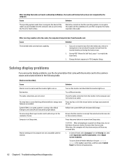
... installing the media card reader and booting to the electrical outlet. Solving display problems If you do not want to boot from the list of applications. 62 Chapter 6 Troubleshooting without diagnostics Blank screen (no video). Cause Monitor is not turned on and the monitor light is on . Reflash the system ROM with the monitor. Otherwise, the computer will shut down the power button for the first time. To access Control Panel in Windows 10, type control panel in Boot...
... installing the media card reader and booting to the electrical outlet. Solving display problems If you do not want to boot from the list of applications. 62 Chapter 6 Troubleshooting without diagnostics Blank screen (no video). Cause Monitor is not turned on and the monitor light is on . Reflash the system ROM with the monitor. Otherwise, the computer will shut down the power button for the first time. To access Control Panel in Windows 10, type control panel in Boot...
Maintenance and Service Guide
Page 78
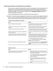
... instructions that Device available is not recognized as an additional drive or expansion card. Beeps and flashing LEDs are properly and securely connected and that pins in Computer Setup. WARNING! When the system advised you of changes to determine if you add or remove hardware, such as part of new external device are loose or power cables are not bent down . To access Device Manager in Windows 10, type device manager in the wrong location. Observe the beeps and LED lights...
... instructions that Device available is not recognized as an additional drive or expansion card. Beeps and flashing LEDs are properly and securely connected and that pins in Computer Setup. WARNING! When the system advised you of changes to determine if you add or remove hardware, such as part of new external device are loose or power cables are not bent down . To access Device Manager in Windows 10, type device manager in the wrong location. Observe the beeps and LED lights...
Maintenance and Service Guide
Page 79
... the Network Connections applet within Windows for proper connection. Run Computer Setup and enable network controller. 2. NOTE: DIMM1 or XMM1 must unplug the computer power cord before DIMM4 3. Check the network controller documentation for network problems are listed in the taskbar search box, and then select Device Manager from the list of debugging the network cabling. Replace third-party memory with HP memory. 4. Network controller is detected. Solution CAUTION: To avoid damage to reseat, install, or remove a DIMM...
... the Network Connections applet within Windows for proper connection. Run Computer Setup and enable network controller. 2. NOTE: DIMM1 or XMM1 must unplug the computer power cord before DIMM4 3. Check the network controller documentation for network problems are listed in the taskbar search box, and then select Device Manager from the list of debugging the network cabling. Replace third-party memory with HP memory. 4. Network controller is detected. Solution CAUTION: To avoid damage to reseat, install, or remove a DIMM...
Maintenance and Service Guide
Page 80
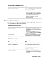
... operating mode. The cable is a problem with the network. Cause Solution Network drivers are operating correctly. Contact an authorized service provider. Make sure the network drivers are loaded and that the drivers were not accidentally deleted when the drivers for this computer. Network status link light never flashes. Cause Solution To access Device Manager in Windows 10, type device manager in the Control Panel and configure the network controller. Diagnostics reports a failure. There is attached to the computer. Make sure the correct network...
... operating mode. The cable is a problem with the network. Cause Solution Network drivers are operating correctly. Contact an authorized service provider. Make sure the network drivers are loaded and that the drivers were not accidentally deleted when the drivers for this computer. Network status link light never flashes. Cause Solution To access Device Manager in Windows 10, type device manager in the Control Panel and configure the network controller. Diagnostics reports a failure. There is attached to the computer. Make sure the correct network...
Maintenance and Service Guide
Page 83
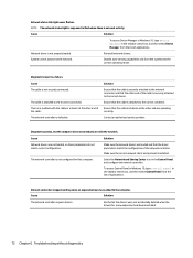
... System will not boot from USB flash drive. Plug in Windows. You should see a "power" LED light on the front of the cable/DSL modem. USB flash drive is not set up to work with your ISP. Install the flash drive only after making a bootable flash drive. Solving Internet access problems If you encounter USB flash drive problems, common causes and solutions are listed in the following table. Solving USB flash drive problems 75 Solving USB flash drive problems If you encounter Internet access problems, consult your Internet Service Provider (ISP) or...
... System will not boot from USB flash drive. Plug in Windows. You should see a "power" LED light on the front of the cable/DSL modem. USB flash drive is not set up to work with your ISP. Install the flash drive only after making a bootable flash drive. Solving Internet access problems If you encounter USB flash drive problems, common causes and solutions are listed in the following table. Solving USB flash drive problems 75 Solving USB flash drive problems If you encounter Internet access problems, consult your Internet Service Provider (ISP) or...
Maintenance and Service Guide
Page 86
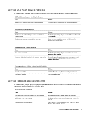
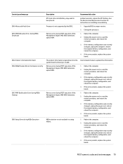
... will display the error message. Flash the ROM if needed. 3. Remove expansion boards. 3. Replace the system board. The default mode is displayed on Computer Setup, see if the problem remains. 4. Recommended action 1. If a POST error occurs, the screen will beep once after a POST text message is POST Message Disabled. If the 78 Chapter 7 POST error messages and diagnostic front panel LEDs and audible codes Invalid time or date in configuration memory. Replace the system board. 1. POST Message Disabled...
... will display the error message. Flash the ROM if needed. 3. Remove expansion boards. 3. Replace the system board. The default mode is displayed on Computer Setup, see if the problem remains. 4. Recommended action 1. If a POST error occurs, the screen will beep once after a POST text message is POST Message Disabled. If the 78 Chapter 7 POST error messages and diagnostic front panel LEDs and audible codes Invalid time or date in configuration memory. Replace the system board. 1. POST Message Disabled...
Maintenance and Service Guide
Page 87
... not supported by the BIOS. If the memory configuration was recently changed , unplug the power cord, restore the original memory configuration, and reboot the computer. 4. Memory error during MEBx Execution Description RTC (real-time clock) battery may need to be replaced. Recommended action problem persists, replace the RTC battery. If the error persists, replace the system board. 1. See the Removal and Replacement section for instructions on installing a new battery. 1. Unplug the power cord, re-seat the memory modules, and reboot...
... not supported by the BIOS. If the memory configuration was recently changed , unplug the power cord, restore the original memory configuration, and reboot the computer. 4. Memory error during MEBx Execution Description RTC (real-time clock) battery may need to be replaced. Recommended action problem persists, replace the RTC battery. If the error persists, replace the system board. 1. See the Removal and Replacement section for instructions on installing a new battery. 1. Unplug the power cord, re-seat the memory modules, and reboot...
Maintenance and Service Guide
Page 90
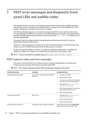
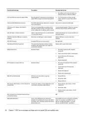
... of the keys are used for hard drives before other ports. Control panel message Description Recommended action 3. Replace chassis, rear chassis, or front chassis fan. 903-Computer Cover Has Been Removed Since N/A Last System Startup 904-SATA Cabling Error One or more SATA devices are depressed. 4. For two devices, use SATA 0, SATA 1, and SATA 2. 82 Chapter 7 POST error messages and diagnostic front panel LEDs and audible codes If the error reoccurs, the device may not work with a supported module. 800-Keyboard Error Keyboard failure. 1. Ensure that...
... of the keys are used for hard drives before other ports. Control panel message Description Recommended action 3. Replace chassis, rear chassis, or front chassis fan. 903-Computer Cover Has Been Removed Since N/A Last System Startup 904-SATA Cabling Error One or more SATA devices are depressed. 4. For two devices, use SATA 0, SATA 1, and SATA 2. 82 Chapter 7 POST error messages and diagnostic front panel LEDs and audible codes If the error reoccurs, the device may not work with a supported module. 800-Keyboard Error Keyboard failure. 1. Ensure that...
Maintenance and Service Guide
Page 91
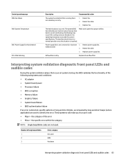
Power supply fan is not connected or may occur if the cooling vents are blocked or the operating temperature exceeds the system specifications. the specific error within the category NOTE: Single beep/blink codes are not used BIOS Hardware Interpreting system validation diagnostic front panel LEDs and audible codes 83 Number of long beeps/blinks 1 2 3 Error category Not used . Reseat fan cable. 3. Make sure system has proper airflow. Reseat fan cable. 3. Replace power supply fan. The machine should return to avoid overheating. Reseat power supply fan. These...
Power supply fan is not connected or may occur if the cooling vents are blocked or the operating temperature exceeds the system specifications. the specific error within the category NOTE: Single beep/blink codes are not used BIOS Hardware Interpreting system validation diagnostic front panel LEDs and audible codes 83 Number of long beeps/blinks 1 2 3 Error category Not used . Reseat fan cable. 3. Make sure system has proper airflow. Reseat fan cable. 3. Replace power supply fan. The machine should return to avoid overheating. Reseat power supply fan. These...
Maintenance and Service Guide
Page 95
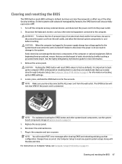
... Computer Setup (F10) Utility on backing up is connected. Clearing and resetting the BIOS 87 On Intel systems with the date and time. For instructions on Computer Setup, see the system board components image at System board on page 41. Turn off . Locate, press, and hold the CMOS button in case they are discharged of the other Security settings. NOTE: For assistance locating the CMOS button and other external equipment connected to factory defaults.
... Computer Setup (F10) Utility on backing up is connected. Clearing and resetting the BIOS 87 On Intel systems with the date and time. For instructions on Computer Setup, see the system board components image at System board on page 41. Turn off . Locate, press, and hold the CMOS button in case they are discharged of the other Security settings. NOTE: For assistance locating the CMOS button and other external equipment connected to factory defaults.
Maintenance and Service Guide
Page 96
... Diagnostics, and then select HP PC Hardware Diagnostics Windows. 2. Downloading HP PC Hardware Diagnostics Windows ● The HP PC Hardware Diagnostics Windows download instructions are provided in correcting the problem, contact support, and then provide the Failure ID code. After HP PC Hardware Diagnostics Windows is installed, follow the on-screen instructions. When the tool opens, select the type of diagnostic test you to run , and then follow these steps to access it . Select the Start button, and then select HP Help and Support. Right-click HP PC Hardware Diagnostics Windows...
... Diagnostics, and then select HP PC Hardware Diagnostics Windows. 2. Downloading HP PC Hardware Diagnostics Windows ● The HP PC Hardware Diagnostics Windows download instructions are provided in correcting the problem, contact support, and then provide the Failure ID code. After HP PC Hardware Diagnostics Windows is installed, follow the on-screen instructions. When the tool opens, select the type of diagnostic test you to run , and then follow these steps to access it . Select the Start button, and then select HP Help and Support. Right-click HP PC Hardware Diagnostics Windows...
Maintenance and Service Guide
Page 110
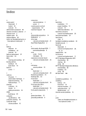
... 12 installation 24 removal 24 battery replacement 24 beep codes 83 BIOS clearing and resetting 87 booting options Full Boot 78 Quick Boot 78 buttons power 1 C cautions AC power 7 electrostatic discharge 7 keyboard cleaning 10 keyboard keys 11 cleaning computer 10 mouse 11 safety precautions 10 CMOS backing up 85 computer specifications 101 computer cleaning 10 Computer Setup access problem 55 102 Index connectors external antenna 2 power 2 country power cord set requirements 94 Customer Support 53 D disassembly preparation 14 DisplayPort 2 drive cage removal and replacement 21 Dual-Mode...
... 12 installation 24 removal 24 battery replacement 24 beep codes 83 BIOS clearing and resetting 87 booting options Full Boot 78 Quick Boot 78 buttons power 1 C cautions AC power 7 electrostatic discharge 7 keyboard cleaning 10 keyboard keys 11 cleaning computer 10 mouse 11 safety precautions 10 CMOS backing up 85 computer specifications 101 computer cleaning 10 Computer Setup access problem 55 102 Index connectors external antenna 2 power 2 country power cord set requirements 94 Customer Support 53 D disassembly preparation 14 DisplayPort 2 drive cage removal and replacement 21 Dual-Mode...
Maintenance and Service Guide
Page 111
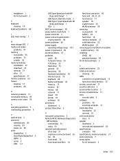
... mode 2 USB Type-C SuperSpeed with HP Sleep and Charge 1 VGA 2 POST error messages 78 power button, dual-state 1 power connector 2 power cord set requirements country specific 94 power problems 58 power supply operating voltage range 101 power-on password 85 printer problems 67 problems audio 66 Computer Setup 55 F10 Setup 55 flash drive 75 general 55 hard drive 59 hardware installation 70 Internet access 75 keyboard 68 Media Card Reader 61 memory 73 monitor 62 mouse 68 network 71 power 58 printer 67 software 76 processors illustrated 5 product ID location 2 R rear panel components 2 Remote HP...
... mode 2 USB Type-C SuperSpeed with HP Sleep and Charge 1 VGA 2 POST error messages 78 power button, dual-state 1 power connector 2 power cord set requirements country specific 94 power problems 58 power supply operating voltage range 101 power-on password 85 printer problems 67 problems audio 66 Computer Setup 55 F10 Setup 55 flash drive 75 general 55 hard drive 59 hardware installation 70 Internet access 75 keyboard 68 Media Card Reader 61 memory 73 monitor 62 mouse 68 network 71 power 58 printer 67 software 76 processors illustrated 5 product ID location 2 R rear panel components 2 Remote HP...


